
As a project engineer, you meticulously calculate major friction losses in your piping network, but what about the so-called “minor losses” from valves? Ignoring or miscalculating the ball valve loss coefficient can lead to underperforming systems, unexpected pressure drops, and increased energy costs. This oversight means your pumps may have to work harder, efficiency drops, and the total cost of ownership (TCO) for your project spirals upward. A single miscalculation can jeopardize system reliability and your reputation for delivering efficient, on-spec projects. This guide provides a clear, actionable breakdown of the ball valve loss coefficient (K-factor), helping you learn how to accurately calculate it, understand the factors that influence it, and make informed valve selections to ensure your fluid systems operate at peak efficiency.
What is the ball valve loss coefficient?
What is the K-Factor?
The ball valve loss coefficient, or K-factor, is a dimensionless value that quantifies the energy lost as fluid passes through the valve. But what does that mean in practice? It is essentially a measure of the valve’s resistance to flow, a critical parameter in hydraulic calculations.
- High K-factor = High resistance and pressure drop.
- Low K-factor = Low resistance and minimal pressure drop.
Key Takeaway: The K-factor is your primary tool for measuring a valve’s impact on system pressure.
Why Minor Losses Aren’t Minor
You must challenge the term “minor loss,” as in systems with many fittings or short pipe runs, these losses can exceed major frictional losses. You might be wondering how this is possible. An accumulation of minor losses from several valves can lead to significant system inefficiency and operational headaches.
- Impacts pump sizing and selection.
- Increases operational energy consumption.
- Can cause insufficient flow at the point of use.
Key Takeaway: Aggregated minor losses are a major factor in overall system performance and cost.
Impact on System Efficiency
The ball valve loss coefficient is directly linked to overall system efficiency and power consumption. Higher pressure drops across valves require more pump energy to maintain the desired flow rate, which directly impacts your operational budget. Here’s the bottom line.
- Lower K-factors reduce the load on pumps.
- Efficient valve selection lowers long-term energy bills.
- Contributes to a lower Total Cost of Ownership (TCO).
Key Takeaway: A low ball valve loss coefficient is directly tied to lower energy costs and higher system efficiency.
| K-Factor Range | Resistance Level | System Impact |
|---|---|---|
| 0.05 – 0.5 | Very Low | Ideal for efficiency, minimal pressure drop |
| 0.5 – 5.0 | Low to Moderate | Acceptable for many standard applications |
| 5.0 – 200+ | High to Extreme | Significant pressure drop, often in throttling |
This table shows the direct correlation between the K-factor and its practical effect on your fluid network’s performance.
How to calculate ball valve loss coefficient
What is the K-Factor Formula?
The primary formula for calculating pressure drop from the K-factor is essential for any engineer’s toolkit. Let’s break that down. This equation allows you to convert the dimensionless K-factor into a tangible pressure loss value for your system.
ΔP = K * ρ * V² / 2- ΔP = Pressure drop (the loss you’re calculating).
- K = The ball valve loss coefficient from manufacturer data.
- ρ = Density of your fluid.
- V = Velocity of your fluid.
Key Takeaway: This formula is the standard for converting a valve’s K-factor into a real-world pressure drop.
Using the Flow Coefficient (Cv)
Manufacturers often provide a Flow Coefficient (Cv or Kv ) instead of a K-factor in their technical datasheets. So, how do you use it? This value is a measure of flow capacity and can be easily converted to a K-factor for use in standard loss calculations.
- Cv measures flow capacity (gallons per minute at 1 psi drop).
- Higher Cv means lower resistance.
- Cv can be converted to a K-factor for use in standard loss equations.
Key Takeaway: If you only have a Cv value, you can still calculate the ball valve loss coefficient.
Practical Calculation Steps
By following a clear, step-by-step process, you can accurately determine the pressure loss for any valve. Ready to put it all together? This simple procedure removes the guesswork from your hydraulic calculations.
- Identify the valve’s K-factor (or calculate from Cv ).
- Determine your fluid’s density and velocity.
- Plug the values into the ΔP formula.
- The result is your expected pressure drop across the valve.
Key Takeaway: Following these steps ensures you can accurately predict the pressure loss for any ball valve in your system.
| Parameter | Symbol | Unit | Example Value |
|---|---|---|---|
| Loss Coefficient | K | Dimensionless | 0.2 |
| Fluid Density | ρ | kg/m³ | 998 (Water) |
| Fluid Velocity | V | m/s | 2 |
| Pressure Drop | ΔP | Pa (Pascals) | 79.84 |
This table summarizes the inputs and a sample output for a typical pressure drop calculation.
Factors of a ball valve loss coefficient
How Does Fluid Viscosity Affect It?
While the standard K-factor formula doesn’t explicitly include viscosity, it’s a critical real-world factor you cannot ignore. But there’s a catch. More viscous fluids like oils create significantly more internal friction and resistance, which increases the effective pressure drop.
- Standard K-factors are based on water.
- High-viscosity fluids generate more internal friction.
- Correction factors may be needed for accurate calculations with viscous media.
Key Takeaway: The stated ball valve loss coefficient is a baseline; highly viscous fluids will increase actual pressure loss.
The Role of Fluid Velocity
The velocity term ( V² ) in the pressure loss formula has an exponential impact that many engineers underestimate. This is where it gets interesting. Doubling the fluid velocity through your pipe will actually quadruple the pressure loss across the same valve.
- Velocity is the most sensitive variable in the equation.
- High-velocity systems are extremely sensitive to K-factors.
- Slightly reducing velocity can yield significant energy savings.
Key Takeaway: Fluid velocity has a squared relationship with pressure loss, making it a critical factor to manage.
Does Reynolds Number Matter?
The Reynolds Number ( Re ) is a dimensionless value used to predict flow patterns, specifically the regime of flow (laminar vs. turbulent). What’s the real story? K-factors are generally considered constant for fully turbulent flow, which is the most common condition in industrial piping systems.
- Turbulent Flow ( Re > 4000): K-factor is stable.
- Laminar Flow ( Re < 2000): K-factor can become dependent on Re , increasing as flow slows.
- Most industrial applications operate in the turbulent range.
Key Takeaway: For most B2B applications, you can assume the ball valve loss coefficient is independent of the Reynolds Number.
| Influencing Factor | Impact on Pressure Loss | Key Consideration for You |
|---|---|---|
| Fluid Viscosity | Increases loss (especially for non-water media) | Use correction factors for viscous fluids. |
| Fluid Velocity | Exponential increase (V²) | Small changes in velocity cause large changes in loss. |
| Reynolds Number | Minimal impact in turbulent flow | Typically not a primary concern for industrial systems. |
This table helps you quickly assess how different fluid dynamics affect your loss calculations.
Design’s role in ball valve loss coefficient
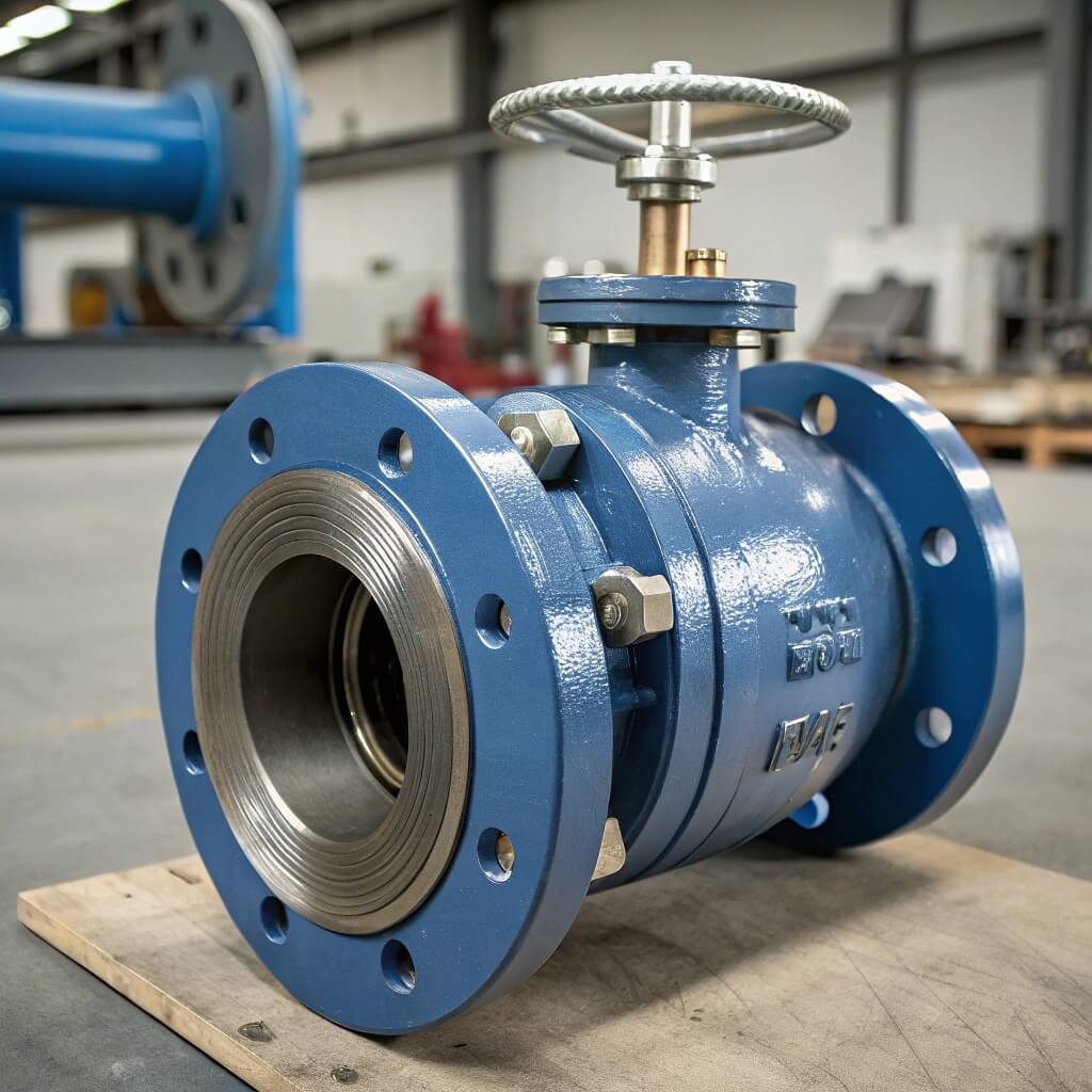
What is a Full Port Ball Valve?
A full port, or full bore, ball valve is designed so that its internal diameter matches the diameter of the connected pipe. Here’s the key advantage. This creates a straight, unobstructed flow path that minimizes resistance and energy loss.
- Creates minimal turbulence.
- Results in the lowest possible ball valve loss coefficient (e.g., K ≈ 0.1 or less).
- Ideal for applications where flow efficiency is paramount.
Key Takeaway: Full port valves are the top choice for minimizing pressure drop and maximizing flow.
What is a Reduced Port Ball Valve?
A reduced port, or standard port, ball valve has an internal bore that is smaller than the connecting pipe’s diameter, often one nominal pipe size down. So why would you choose one? While this constriction increases the loss coefficient, these valves are often more compact and economical.
- Higher ball valve loss coefficient (e.g., K ≈ 0.2 to 0.5).
- More compact and economical than full port valves.
- Suitable where some pressure drop is acceptable.
Key Takeaway: Reduced port valves are a cost-effective option, but at the expense of a higher loss coefficient.
How to Choose Between Them?
Selecting between full port and reduced port valves requires a careful evaluation of your project’s priorities. It comes down to this. The choice is a direct trade-off between the initial capital cost of the valve and the long-term operational efficiency, or TCO.
- Choose Full Port if: Minimizing pressure drop is critical, the system is sensitive to energy loss, or you need to run pigs through the line.
- Choose Reduced Port if: Initial cost is a primary driver, and a moderate pressure drop is acceptable within system design parameters.
Key Takeaway: Your choice depends on balancing the upfront valve cost against the long-term energy cost of a higher ball valve loss coefficient.
| Valve Type | Typical K-Factor | Cost | Best For |
|---|---|---|---|
| Full Port | < 0.1 | Higher | Maximum efficiency, minimal pressure loss |
| Reduced Port | 0.2 – 0.5 | Lower | Cost-sensitive projects, non-critical flow paths |
This comparison clarifies the fundamental trade-off between the two main ball valve designs.
Angle’s effect on ball valve loss coefficient
Fully Open (90 Degrees)
When a ball valve is in its fully open position, which corresponds to a 90-degree rotation of the stem, it offers the least possible resistance to flow. As you’d expect… This is the operating point where the valve is most efficient, and it corresponds to the baseline K-factor published by the manufacturer.
- The flow is nearly unobstructed.
- This is the point of maximum efficiency.
- The ball valve loss coefficient is at its absolute minimum.
Key Takeaway: The manufacturer’s stated K-factor applies only when the valve is 100% open.
Partially Closed (Throttling)
As you begin to close a ball valve, the edge of the ball moves into the flow path, creating a significant obstruction that induces severe turbulence. This is where the numbers get crazy. The loss coefficient does not increase linearly; it rises exponentially, making flow control difficult and inefficient.
- The ball valve loss coefficient increases exponentially as the valve closes.
- A valve 1/3 closed can have a K-factor over 5.0.
- A valve 2/3 closed can see the K-factor skyrocket to over 200.
Key Takeaway: Partially closing a ball valve dramatically increases its loss coefficient.
Why Ball Valves Aren’t for Throttling
Based on their flow characteristics, ball valves are generally poor choices for applications requiring flow regulation, or throttling. So what’s the verdict? For these applications, a globe valve is far superior, as it is designed for linear flow control and can withstand the erosive forces of a partially open state.
- Non-linear flow control.
- High potential for seat erosion and damage.
- Extreme and difficult-to-predict pressure losses.
Key Takeaway: Use ball valves for on/off service; choose a globe valve if you need to regulate flow, as the ball valve loss coefficient becomes unmanageable.
| Opening Angle | Approximate K-Factor | Flow Condition |
|---|---|---|
| 90° (Fully Open) | ~0.1 | Unrestricted, minimal loss |
| 60° (1/3 Closed) | ~5.5 | Moderate turbulence and loss |
| 30° (2/3 Closed) | ~210 | Extreme turbulence, severe loss |
This data starkly illustrates the exponential rise in the K-factor as a ball valve is used for throttling.
Managing ball valve loss coefficient
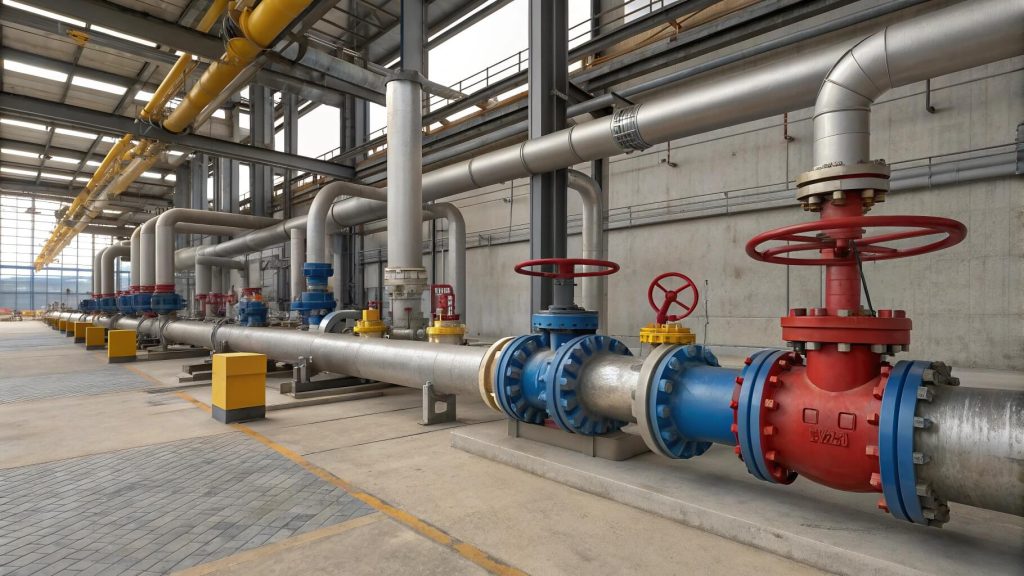
Strategic Valve Placement
To optimize your system, you should place valves in locations where any associated pressure drop is less critical to overall performance. Think like a system architect. By planning the layout carefully, you can avoid clustering multiple high-loss components together, which can compound their negative effects.
- Place valves away from other fittings like elbows or tees to allow flow to stabilize.
- Use full port valves in long, critical pipe runs.
- Consider reduced port valves for less critical branches or drains.
Key Takeaway: Thoughtful valve placement can help mitigate the cumulative impact of minor losses on your system.
Proper Valve Sizing
Oversizing or undersizing a valve is a frequent error that can severely compromise system performance and efficiency. It’s a common mistake. An oversized valve can lead to poor control characteristics, while an undersized valve creates excessive pressure drop and fluid velocity, increasing energy use and wear.
- Match the valve size to the required flow rate, not just the pipe size.
- Consult flow capacity charts ( Cv values) during selection.
- Proper sizing ensures the valve operates in its most efficient range.
Key Takeaway: Sizing a valve correctly is just as important as selecting the right type to manage the ball valve loss coefficient.
Partnering with a Technical Supplier
Working with a manufacturer who provides comprehensive and reliable technical data is one of the most effective ways to ensure system success. Here’s how to de-risk your project. A knowledgeable supplier can provide accurate K-factors, Cv data, and expert selection advice tailored to your specific application.
- Request detailed technical datasheets for any valve you consider.
- Consult with their engineering team for complex applications.
- A good partner helps you optimize for TCO, not just initial price.
Key Takeaway: Leveraging your supplier’s expertise is the best way to ensure your valve selection minimizes the ball valve loss coefficient and meets project goals.
| Management Strategy | Action for You | Expected Outcome |
|---|---|---|
| Strategic Placement | Analyze pipe layout; avoid clustering fittings | Reduced cumulative pressure drop |
| Proper Sizing | Calculate requiredCv; don’t just match pipe size | Optimal control and efficiency |
| Supplier Partnership | Request full technical data and consult experts | Accurate calculations and reliable performance |
This table provides an actionable checklist for proactively managing minor losses in your designs.
Conclusion
Accurately accounting for the ball valve loss coefficient is not a minor detail—it is fundamental to designing efficient, reliable, and cost-effective fluid systems. By understanding the difference between full and reduced ports, the dramatic effect of the opening angle, and how to use K-factor formulas, you can avoid costly performance issues. For projects where reliability is non-negotiable, you need a partner, not just a parts provider. RUITO is a specialist manufacturer committed to being the most trusted mid-to-high-end valve exporter. We provide fully certified valves with complete technical documentation, ensuring you can precisely calculate and manage every variable. Contact our engineering team today to get the right valve selection advice for your next project and eliminate the guesswork.
FAQ Section
Is a higher ball valve loss coefficient always bad?
Not necessarily. In on/off applications where the valve is almost always fully open or fully closed, a slightly higher K-factor (like from a reduced port valve) might be an acceptable trade-off for a lower initial cost. It only becomes a significant problem in systems sensitive to pressure drop or where valves are used for throttling.
Can I use a reduced port ball valve to save money?
Yes, you can, but only if your system design can tolerate the higher pressure drop. Reduced port valves are more economical upfront, but the higher ball valve loss coefficient increases long-term energy costs. It’s a trade-off you must calculate.
What’s the best way to get an accurate K-factor?
The most reliable way is to obtain it directly from the manufacturer’s technical datasheet. Reputable manufacturers like RUITO perform tests to provide accurate K-factors or Cv values for their products. Avoid using generic, tabulated values if possible.
How do I know if my pressure drop is too high?
You’ll know if the pressure or flow rate at the point of use is below your system’s required specifications. This often manifests as underperforming equipment, slow process cycles, or pumps running at maximum capacity without achieving the target output.
Can I install a ball valve right after an elbow?
It’s not ideal. Placing a valve immediately after another fitting like an elbow can compound turbulence and lead to a higher effective loss coefficient than the two components would have individually. If possible, allow for a straight pipe run of 5-10 pipe diameters between fittings to let the flow stabilize.