RUITO Header Component
RUITO Balancing Valve - Professional Flow Control Solutions Module Optimization RUITO Balancing Valve - Professional Flow Control Solutions Hero Module Optimization
Industrial Hydronic System and Valves

Precision Balancing Valve Solutions for Reliable Hydronic Performance

Engineered to eliminate flow imbalance, reduce energy waste, and ensure consistent system efficiency across your entire hydraulic network.

Accurate Flow Control
Energy Efficiency
Certified Quality
Module Optimization

Where Projects Fail Without Proper Balancing

Critical breakpoints that turn system design into operational nightmares

Design

Flow calculations assume ideal conditions that never exist in real installations

Procurement

Budget cuts force valve downgrades that compromise entire system performance

Installation

Incorrect valve orientation creates unrecoverable pressure drops and turbulence

Commissioning

No measurement ports means balancing becomes guesswork instead of precision

Acceptance

System passes initial tests but degrades within months due to inadequate valve adjustment range

Need help identifying risks in your current project stage?

Cost of Inadequate Balancing Optimization

The True Cost of Inadequate Flow Balancing

Beyond the valve price: What poor balancing actually costs your project

Industrial Pump System Energy Waste

Energy Waste

Unbalanced systems force pumps to over-compensate, consuming excess energy to overcome resistance and maintain minimum flow to distant zones.

Pump energy consumption increases by 15-40% compared to properly balanced systems

Temperature Control Issues

Comfort Failures

Near-loop zones receive excessive flow while distant zones starve, creating temperature differentials that trigger constant occupant complaints.

Temperature variations exceed ±3°C between zones, violating design specifications and tenant agreements

Project Delays

Commissioning Delays

Systems without proper balancing valves require multiple site visits, iterative adjustments, and extended testing periods to achieve acceptable performance.

Project handover delays of 2-6 weeks incur penalty costs and damage contractor reputation

Equipment Maintenance

Equipment Degradation

Continuous over-pumping and pressure fluctuations accelerate wear on seals, bearings, and heat exchangers throughout the system.

Maintenance interventions double within first 3 years, with component failures occurring years before design life

Calculate potential savings for your specific project

What is a Balancing Valve

Core components engineered to deliver precise flow control and system stability

Balancing valve cross-section diagram
1

Flow Regulation Mechanism

Precision-machined orifice and plug assembly provides linear or characterized flow control across the valve's adjustment range, enabling accurate matching to design flow requirements.

2

Differential Pressure Control

Integrated pressure regulation cartridge maintains constant differential pressure regardless of system fluctuations, preventing flow variation when upstream conditions change.

3

Measurement Ports

Factory-calibrated test points enable direct pressure drop measurement, eliminating estimation and allowing verification of actual flow against design specifications during commissioning.

4

Sealing System

EPDM or PTFE seals rated for continuous operation at design temperature and pressure, with leak rates below 0.01% of Kvs to prevent system losses and maintain adjustment accuracy.

See detailed technical drawings and specifications

Static vs Dynamic Valve Comparison

Static vs Dynamic Balancing Valves

Understanding which valve type matches your system requirements and operational constraints

Static Balancing Valve

Static Balancing Valve

Suitable System Type Constant flow systems with minimal load variation, such as primary chilled water loops and fixed-speed pump circuits
Control Method Manual adjustment of orifice position based on calculated Kv requirement; setting remains fixed during operation
Flow Stability Maintains design flow only when system pressure remains constant; flow varies proportionally with pressure changes
Commissioning Complexity Requires iterative balancing procedures starting from furthest branch; adjustments to one valve affect all downstream zones
System Change Adaptation Requires manual re-balancing when pumps cycle, zones close, or control valves modulate; cannot adapt to dynamic conditions
Initial Cost Lower unit cost; typically 40-60% less expensive than equivalent dynamic valve
Long-term Operational Cost Higher energy cost due to inability to maintain optimization during load changes; requires periodic re-commissioning labor
Dynamic Balancing Valve

Dynamic Balancing Valve

Suitable System Type Variable flow systems with frequent load changes, including VAV systems, two-pipe changeover, and modulating control applications
Control Method Self-acting pressure regulator automatically compensates for system pressure fluctuations without external power or control signal
Flow Stability Maintains preset flow within ±5% across the valve's authority range, regardless of upstream pressure variation
Commissioning Complexity Each valve operates independently; zones can be commissioned in any sequence without affecting adjacent circuits
System Change Adaptation Automatically maintains balance when system configuration changes; no intervention required for routine load variations
Initial Cost Higher unit cost due to integrated pressure regulation cartridge and precision manufacturing requirements
Long-term Operational Cost Lower energy cost through continuous optimization; eliminates re-balancing labor across system lifetime

Not sure which valve type fits your project? Let our engineers guide you.

RUITO Balancing Valve - Modules 6-10 Why Balancing Valves Fail - Optimized

Why Many Balancing Valves Fail

Critical design and manufacturing defects that compromise system performance

Fluid dynamics graph

Inadequate Flow Characterization

Orifice geometry provides non-linear flow response, making precise adjustment impossible because small changes in valve position create disproportionate flow variations at different operating points.

System Consequence

Balancing technicians cannot achieve target flow rates within acceptable tolerance, forcing compromise settings that leave zones under or over-served.

Metal stress and corrosion

Insufficient Pressure Rating

Body and seal materials rated only for nominal system pressure fail when exposed to transient spikes during pump starts, valve closures, or temperature changes.

System Consequence

Seal degradation allows internal leakage that bypasses the adjustment mechanism, eliminating the valve's ability to maintain calibrated flow restriction.

Valve and piping connection

Inadequate Kvs Authority

Valve Kvs too small relative to circuit resistance creates excessive pressure drop, while oversized Kvs provides insufficient control resolution because most adjustment range becomes unusable.

System Consequence

Either pump energy wastes overcoming unnecessary valve resistance, or adjustment sensitivity becomes so coarse that fine-tuning is mechanically impossible.

Measurement instrument

Measurement Port Inaccuracy

Test ports lack factory calibration or suffer from installation-induced pressure tap distortion, making pressure drop readings unreliable for flow calculation.

System Consequence

Commissioning data becomes questionable, preventing verification that actual flow matches design intent and eliminating diagnostic capability for future troubleshooting.

Mechanical spindle detail

Position Memory Loss

Spindle mechanisms lack positive locking or use materials prone to thermal expansion, allowing calibrated positions to drift over time due to vibration or temperature cycling.

System Consequence

System balance deteriorates gradually without obvious cause, requiring repeated commissioning interventions and creating chronic performance complaints.

Verify how RUITO valves eliminate these common failure modes

How to Select Balancing Valve - Optimized

How to Select the Right Balancing Valve

Five critical parameters that determine valve compatibility and long-term performance

Step 01

System Type Identification

Determine whether your application operates with constant flow and fixed pump speed, or variable flow with modulating controls that create changing pressure conditions.

Common Error

Specifying static valves for VAV or two-pipe changeover systems that require dynamic pressure compensation.

Step 02

Design Flow Verification

Calculate actual circuit flow requirements from heat load and temperature differential, then select valve Kvs to achieve 10-30 kPa pressure drop at design flow.

Common Error

Oversizing valves to match pipe diameter rather than flow requirement, creating insufficient pressure drop.

Step 03

Pressure Differential Analysis

Confirm maximum available differential pressure at valve location under worst-case conditions to ensure selected valve can create sufficient restriction.

Common Error

Ignoring pump curves and assuming system static pressure applies at all flow conditions.

Step 04

Temperature & Medium Compatibility

Verify valve body material and seal selection against maximum operating temperature and fluid chemistry including glycol concentration.

Common Error

Specifying standard EPDM seals for systems exceeding 110°C or high-glycol concentration.

Step 05

Standards & Certification Requirements

Identify mandatory compliance requirements including pressure equipment directives, drinking water approvals, and performance testing standards.

Common Error

Discovering missing certifications during project approval stage, forcing last-minute valve changes.

Engineering flow characteristic chart and data analysis

Need assistance matching valves to your specific system parameters?

Common Engineering Applications - Optimized

Common Engineering Applications

Field-proven balancing solutions across diverse system types and operating conditions

Modern glass skyscraper

Commercial HVAC Systems

Ensure uniform temperature control across multi-zone office towers and shopping complexes. Eliminate pressure differentials in high-rise structures to prevent upper-floor starvation and lower-floor overflow.

Industrial factory piping

Industrial Process Cooling

Deliver precise cooling capacity to critical manufacturing equipment and data centers with zero tolerance for temperature excursions. Maintain flow stability during production load shifts.

District heating pipes or urban infrastructure

District Energy Networks

Balance flow across extensive underground distribution networks connecting multiple buildings. Accommodate diverse load profiles and varying distances from the central utility plant.

Discuss your specific application requirements with our technical team

Common Engineering Misconceptions - Optimized Common Engineering Misconceptions - Optimized

Common Engineering Misconceptions

Critical misunderstandings that compromise system performance and project outcomes

Common Misconception

Balancing valves are only needed in poorly designed systems. Proper pipe sizing eliminates the need for flow balancing.

Engineering Reality

Even perfectly sized piping cannot eliminate differential resistance between parallel circuits. Balancing valves are essential to compensate for unavoidable differences in pipe length and fitting count.

Why This Exists

Simplified textbook examples show symmetrical systems, creating the false impression that real installations can achieve this ideal. Actual buildings have architectural constraints that force asymmetrical layouts.

Common Misconception

Ball valves or gate valves can be throttled to balance flow, making dedicated balancing valves an unnecessary cost increase.

Engineering Reality

Isolation valves lack calibrated Kv curves, measurement ports, and position memory. Without measurement capability, throttling becomes trial-and-error guesswork that cannot be documented.

Why This Exists

Short-term testing may appear successful, but without position indicators, settings drift over time through vibration. The lack of immediate failure masks the long-term degradation.

Common Misconception

Once balanced during commissioning, the system will maintain proper flow distribution indefinitely without further intervention.

Engineering Reality

Static systems require re-commissioning whenever pumps are replaced or zones modified. Only dynamic valves automatically maintain balance through system modifications.

Why This Exists

Commissioning reports show passing test results, creating the impression of permanent completion. Operators typically lack the instrumentation to verify ongoing balance, so degradation goes undetected.

Common Misconception

Dynamic balancing valves are premium products only justified for complex systems. Standard projects should use static valves to control costs.

Engineering Reality

Any system with modulating controls or variable speed pumps requires dynamic compensation. The higher initial cost is recovered through eliminated re-commissioning labor and reduced energy.

Why This Exists

First-cost focus during procurement obscures life-cycle analysis. Maintenance and energy costs appear as operational expenses, making it difficult to connect valve selection to downstream costs.

Get technical guidance based on proven engineering principles

RUITO Solutions - Optimized

RUITO Balancing Valve Solutions

Engineered responses to documented system problems with measurable performance outcomes

The Challenge

Inconsistent flow distribution causing temperature gradients and occupant complaints.

Precision adjustment mechanism

Precision Flow Regulation

Linear Kv characteristic across 10:1 adjustment range ensures flow distribution stays within ±5% of design across all circuits.

±5% Accuracy
10:1 Range
The Challenge

Excessive pump energy consumption due to over-pumping and wasted head pressure.

Efficient flow dynamics

Optimized Hydraulic Resistance

Integrated ΔP control eliminates over-pumping. Reduces pump energy consumption by 15-30% compared to unbalanced baselines.

-30% Energy
ΔP Control
The Challenge

Prolonged commissioning timelines with iterative trial-and-error adjustments.

Measurement ports

Rapid Commissioning Protocol

Direct ΔP measurement ports enable single-pass balancing, reducing commissioning time by 40-60%.

50% Faster
Test Ports
The Challenge

Valve settings drift over time due to vibration, thermal cycling, or tampering.

Secure locking mechanism

Position Memory Assurance

Stainless steel spindle with positive mechanical detent and memory stop ensures settings remain accurate for 10+ years.

Memory Stop
10yr Life
The Challenge

Missing certification documentation causing project approval bottlenecks.

Certification documentation

Complete Certification Package

Full CE, WRAS, and EN standards compliance with traceable material documentation provided upfront.

CE / WRAS
Traceable

Match RUITO solutions to your specific system challenges

RUITO Balancing Valve - Modules 11-15 Manufacturing Capability - 1+4 Bento Layout Manufacturing Capability - Immersive Bento Layout Manufacturing Capability & Quality Control

Manufacturing Capability & Quality Control

Verifiable production infrastructure and inspection protocols that ensure consistent product quality

In-House Factory Assembly Line

In-House Factory

Complete valve assembly and testing performed in RUITO-owned facility with direct control over all production stages. We do not outsource critical core assembly processes.

Verifiable Point

Factory audit available with 15-day advance notice for qualified procurement teams

Pressure testing gauge

100% Pressure Test

Every valve undergoes hydrostatic pressure testing at 1.5x rated pressure for minimum 3 minutes.

Verifiable Point

Test certificates provided with serial numbers

Precision caliper measurement

Critical Dimensions

Full dimensional verification of threaded connections and sealing surfaces using calibrated gauges.

Verifiable Point

CMM measurement reports available

Laser marking traceability

Batch Traceability

Complete material tracking from raw casting to finished valve via serialized unique IDs.

Verifiable Point

Material certs linked to valve serials

Auditor checking list

Audit Support

Full facility access for customer-appointed inspectors or certification bodies.

Verifiable Point

Pre-shipment witness testing allowed

Verify our manufacturing capabilities through direct facility assessment

Certifications & Standards - Optimized Certifications & Standards - 3-Column Symmetric

Certifications & Standards Compliance

Third-party verified conformity to international quality and performance requirements

Certifications represent independent verification that products meet defined technical and safety standards. They eliminate procurement risk by confirming compliance before installation and provide documentary evidence required for project approvals.

Quality management system audit

Quality Management Systems

Demonstrates systematic approach to quality control, environmental management, and occupational health across all manufacturing processes.

ISO 9001
ISO 14001
ISO 45001
OHSAS
TUV
SGS
Product compliance certification labels

Product Compliance & Access

Covers EU market access (CE/PED), potable water approvals, and marine classification society approvals for vessel installations.

CE / PED
WRAS
DNV
ABS
DVGW
NSF
Technical engineering standards blueprint

Design & Manufacturing Standards

Defines technical requirements for balancing valve design, materials, pressure testing, and performance verification.

EN 1267
DIN 2401
ANSI
BS EN 215
ISO 5208
API 598

Request specific certification documentation for your project requirements

Engineering Case Studies - ZigZag Layout

Engineering Case Studies

Documented project outcomes demonstrating valve performance in demanding applications

Commercial Office Tower Frankfurt

Commercial Office Tower, Frankfurt

Project Background

32-story tower with VAV HVAC system serving mixed-use spaces including trading floors, conference facilities, and standard office zones requiring precise temperature control.

Engineering Challenge

Original static balancing valves could not maintain flow stability during load variations. Trading floor zones experienced temperature swings exceeding 2°C when adjacent office zones modulated.

Implemented Solution

Replaced 187 static valves with RUITO DN15-DN80 dynamic balancing valves across all VAV terminal zones. Valves specified with ΔP control cartridges rated for 5-50 kPa differential.

Measured Outcome

Temperature stability improved to ±0.8°C across all zones. Pump energy consumption decreased by 23%. System commissioning time reduced from projected 3 weeks to 9 days.

Pharmaceutical Manufacturing Facility

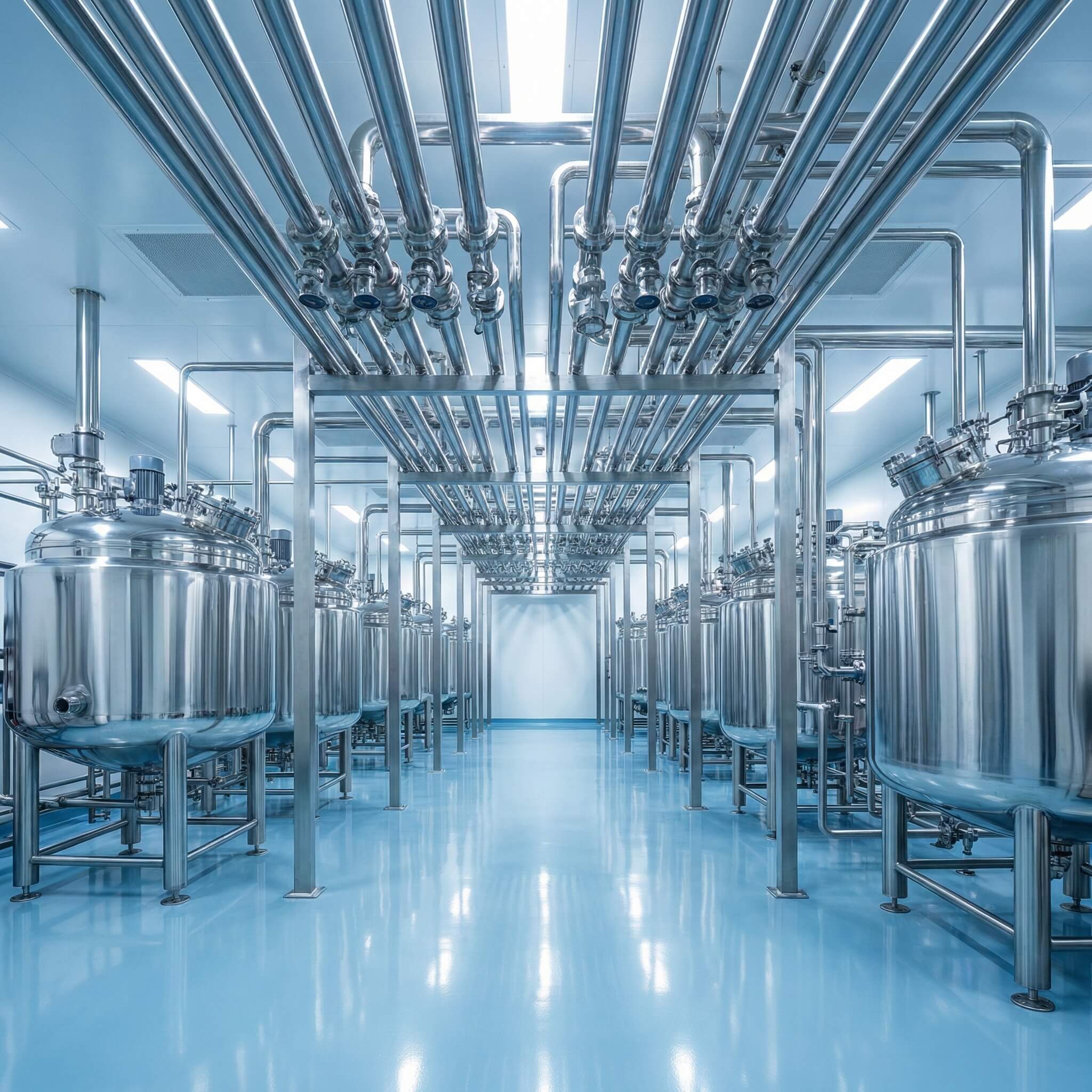
Pharmaceutical Plant, Singapore

Project Background

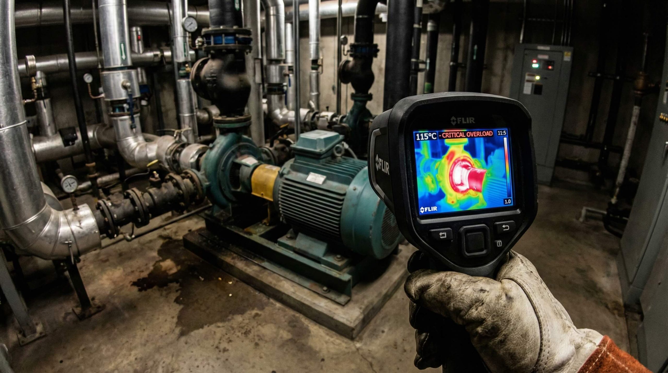
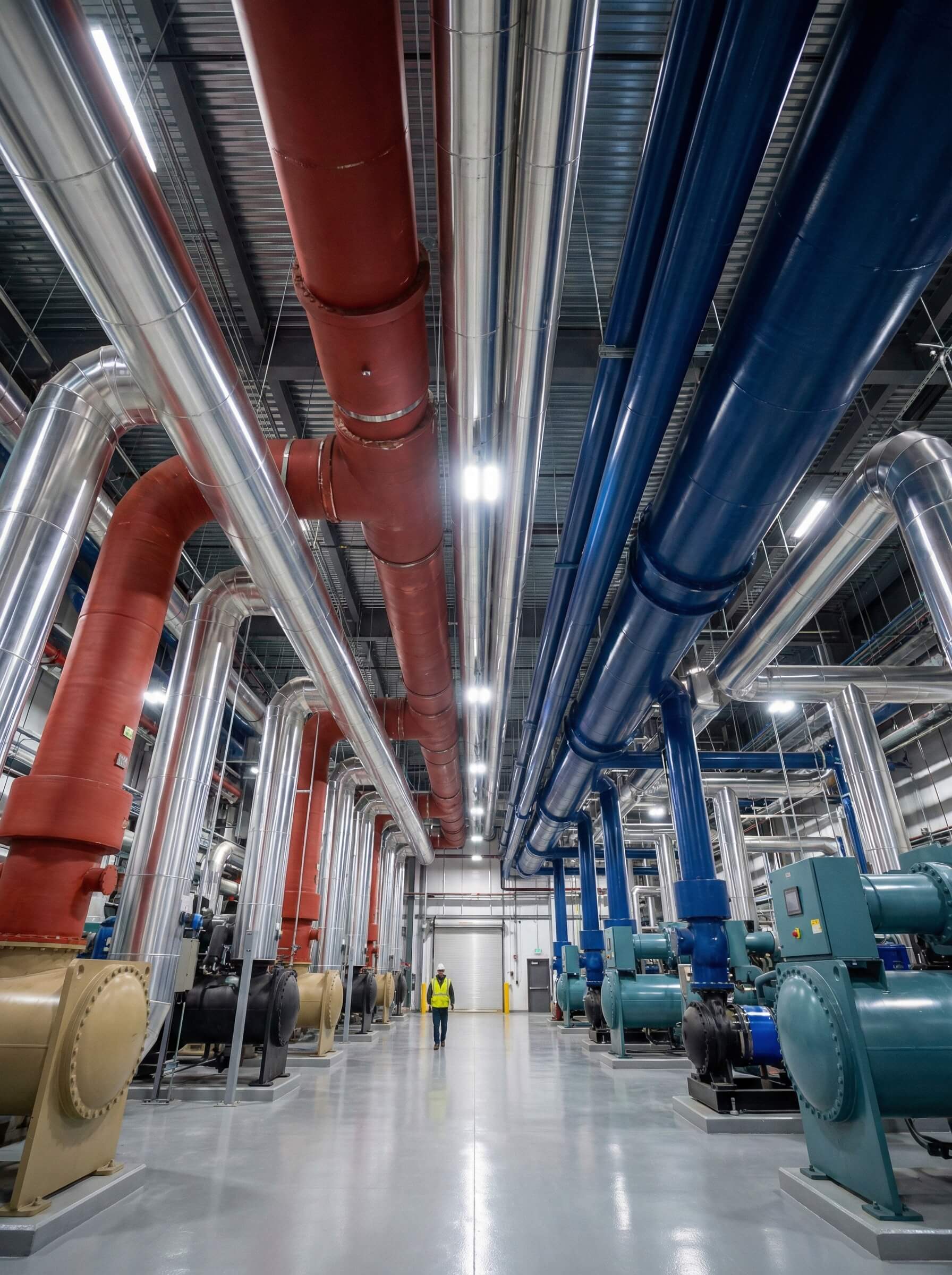
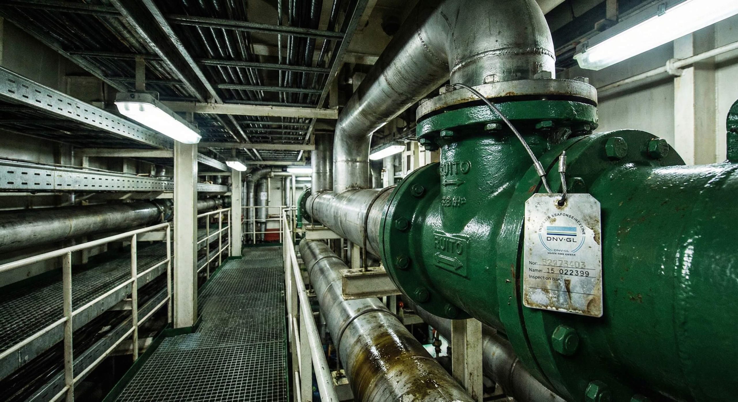
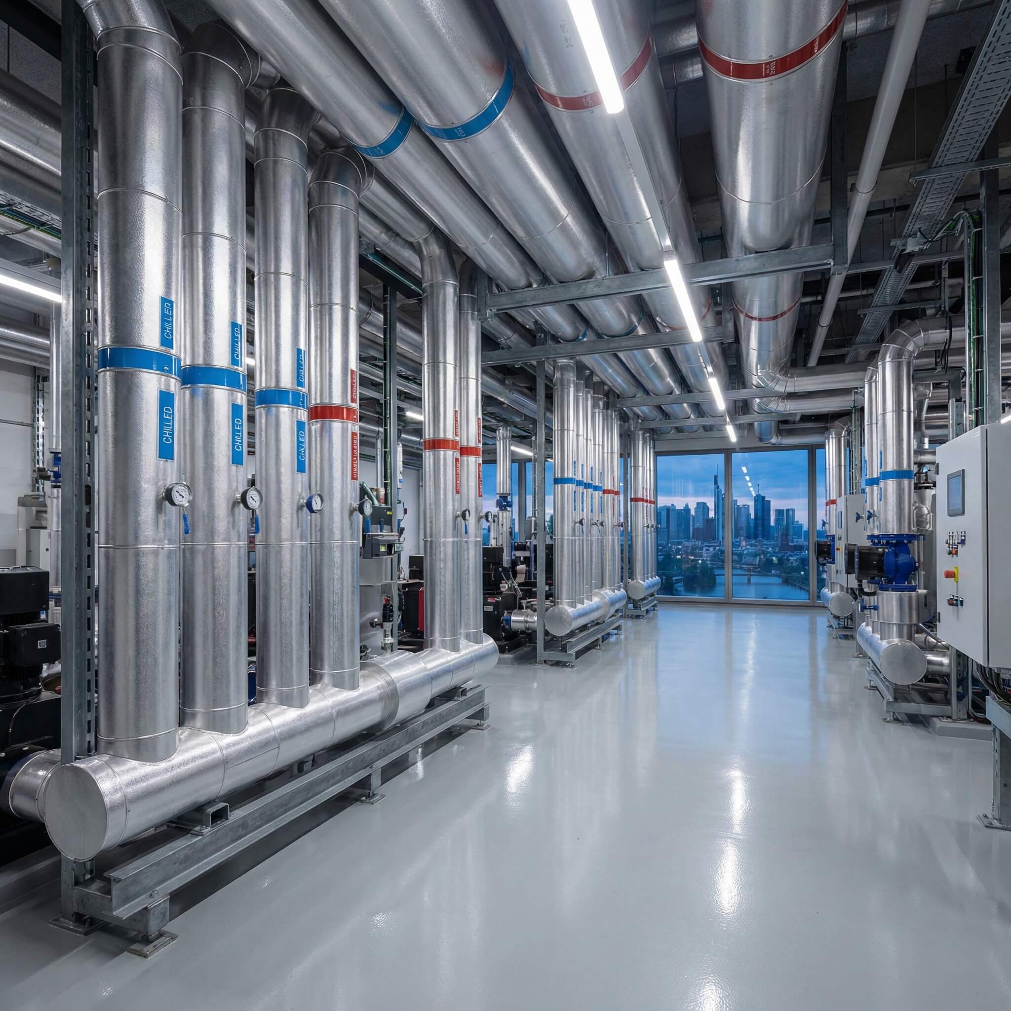
Process cooling system serving temperature-critical production equipment with zero tolerance for thermal excursions that could compromise batch quality or trigger shutdowns.

Engineering Challenge

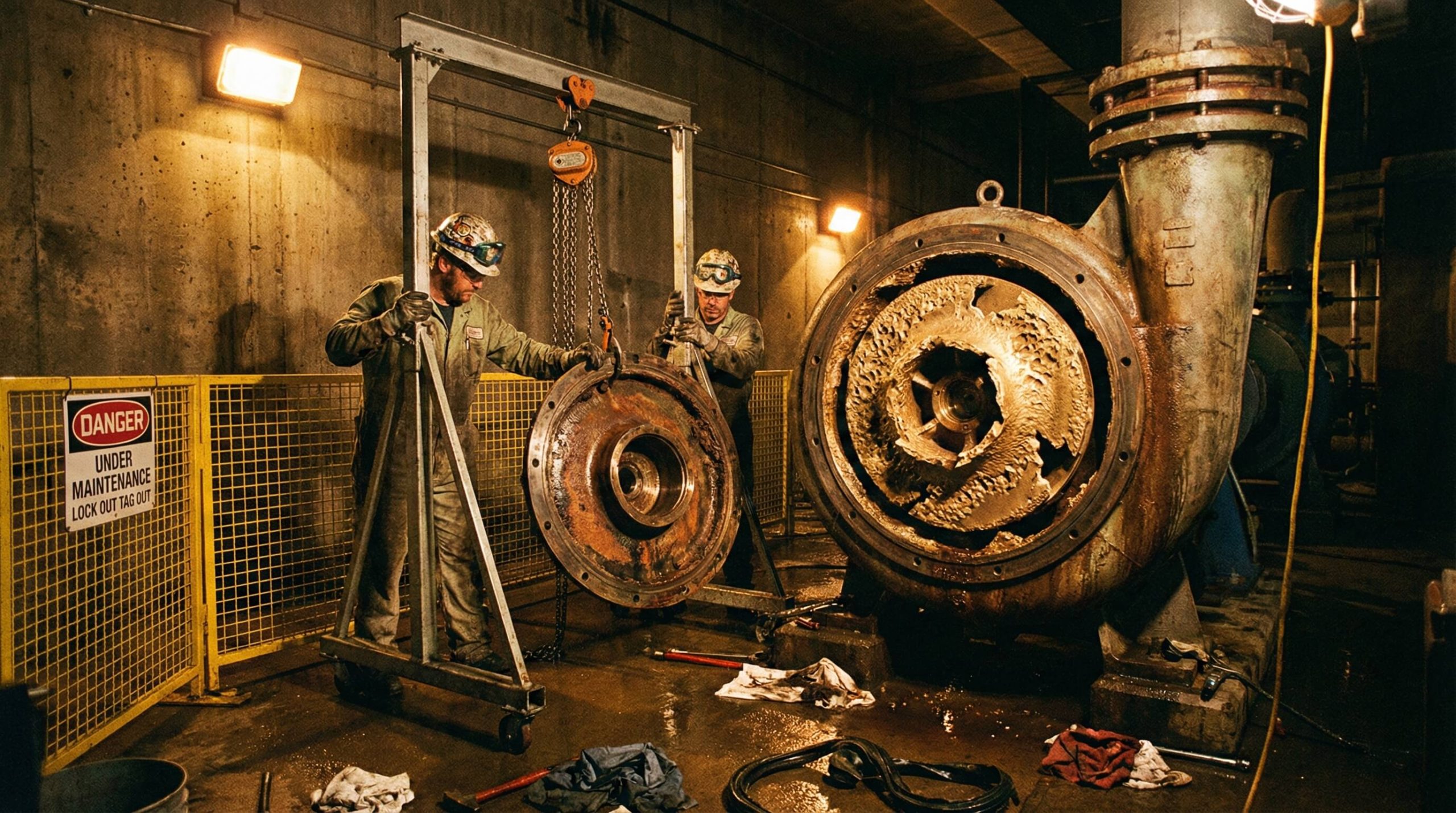
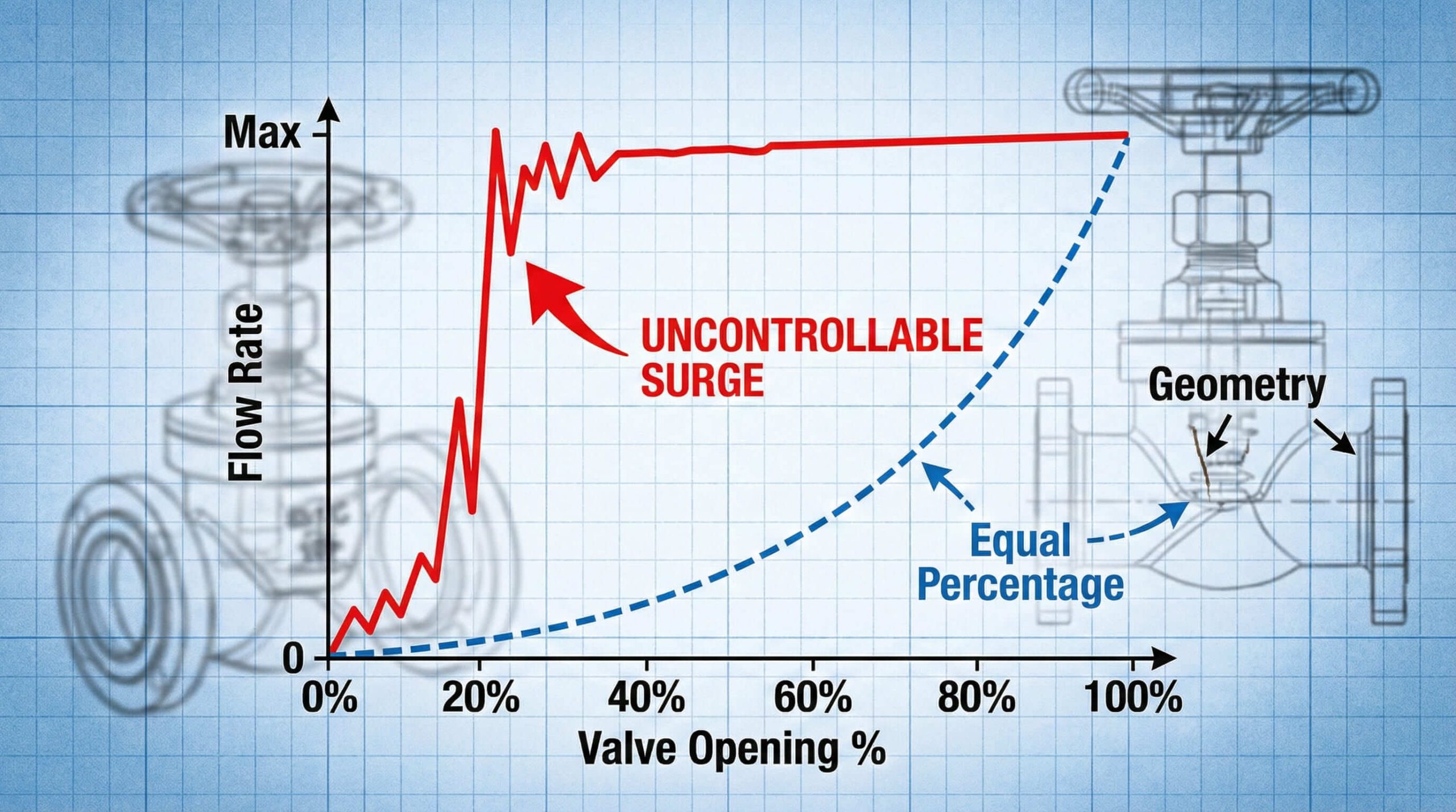
Equipment nearest to cooling plant received excessive flow while distant process lines suffered inadequate cooling. Flow imbalance forced operation at lower setpoints, wasting energy.

Implemented Solution

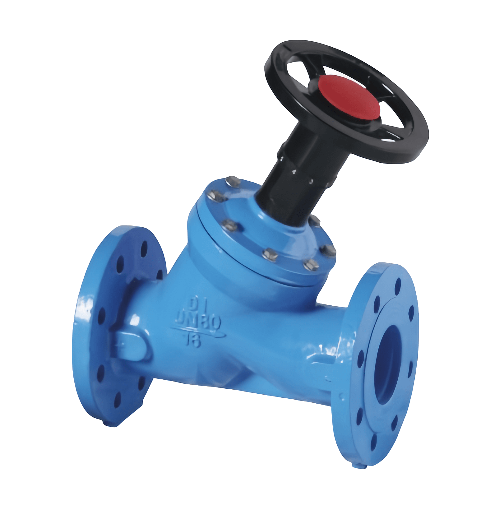
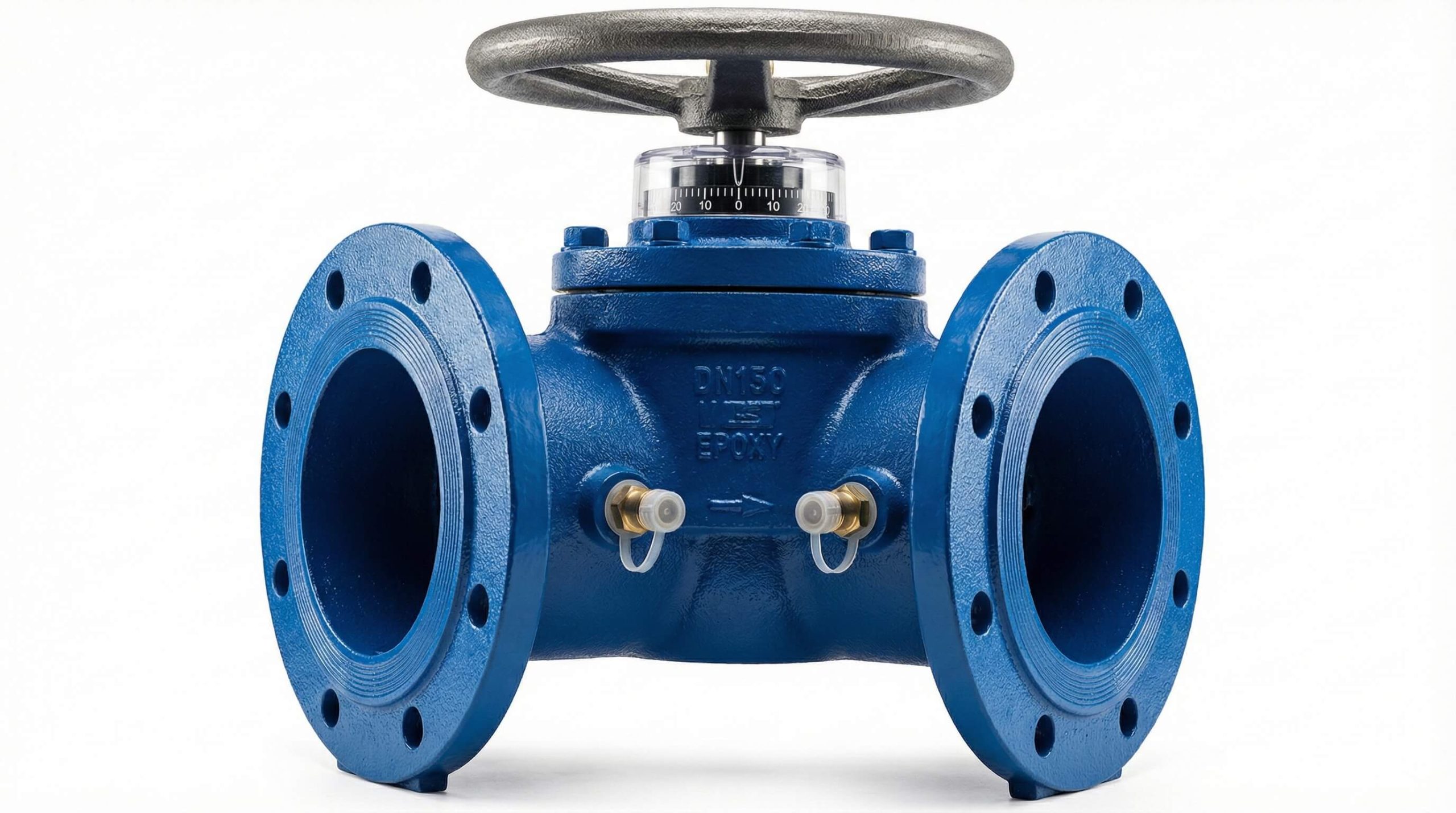
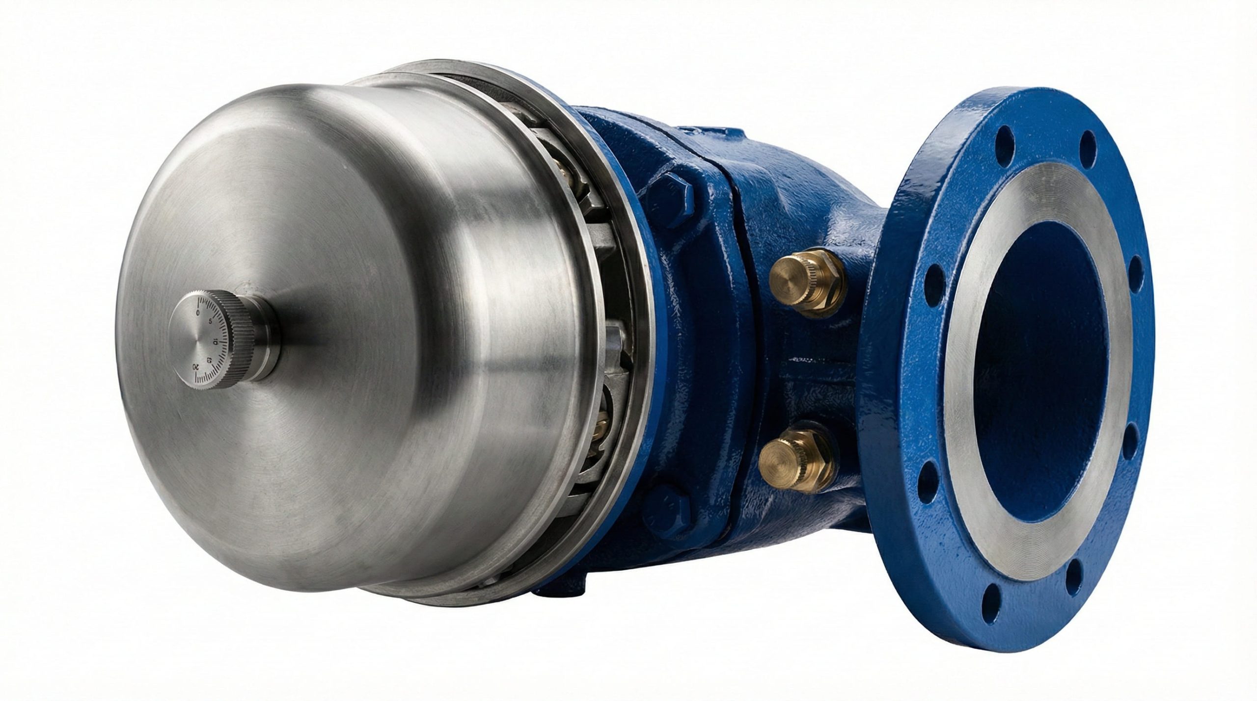
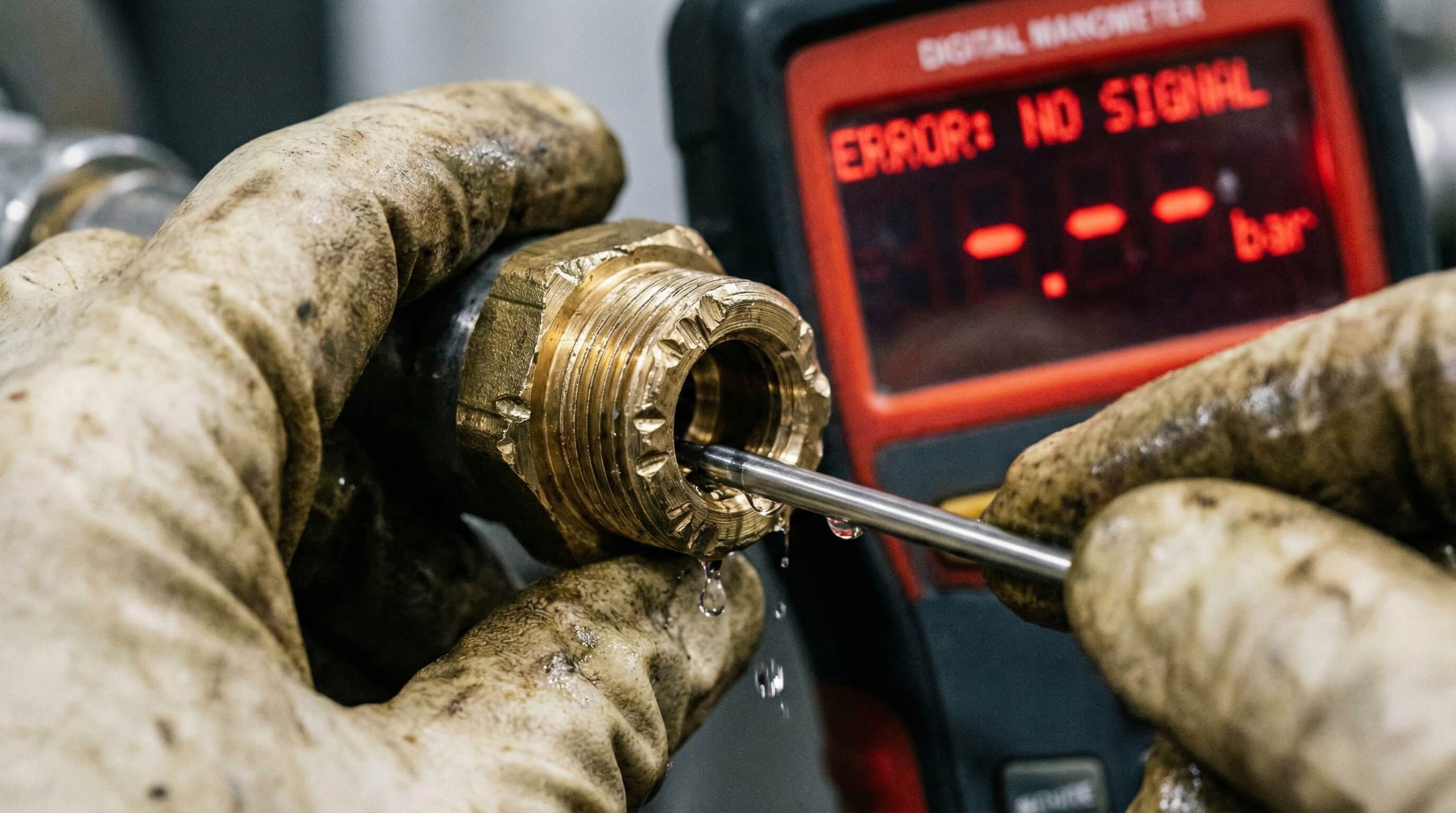
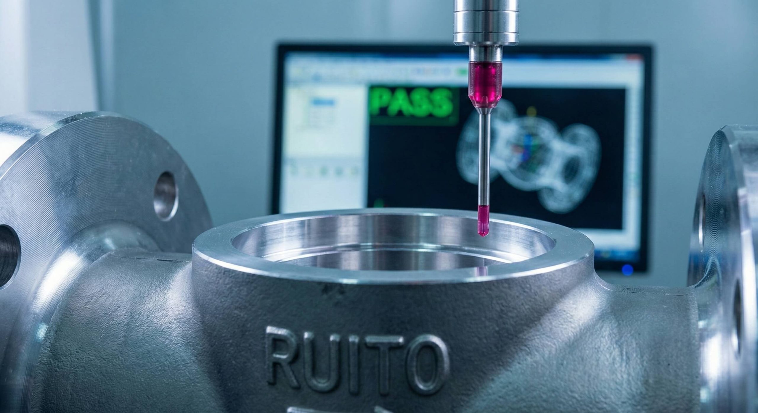
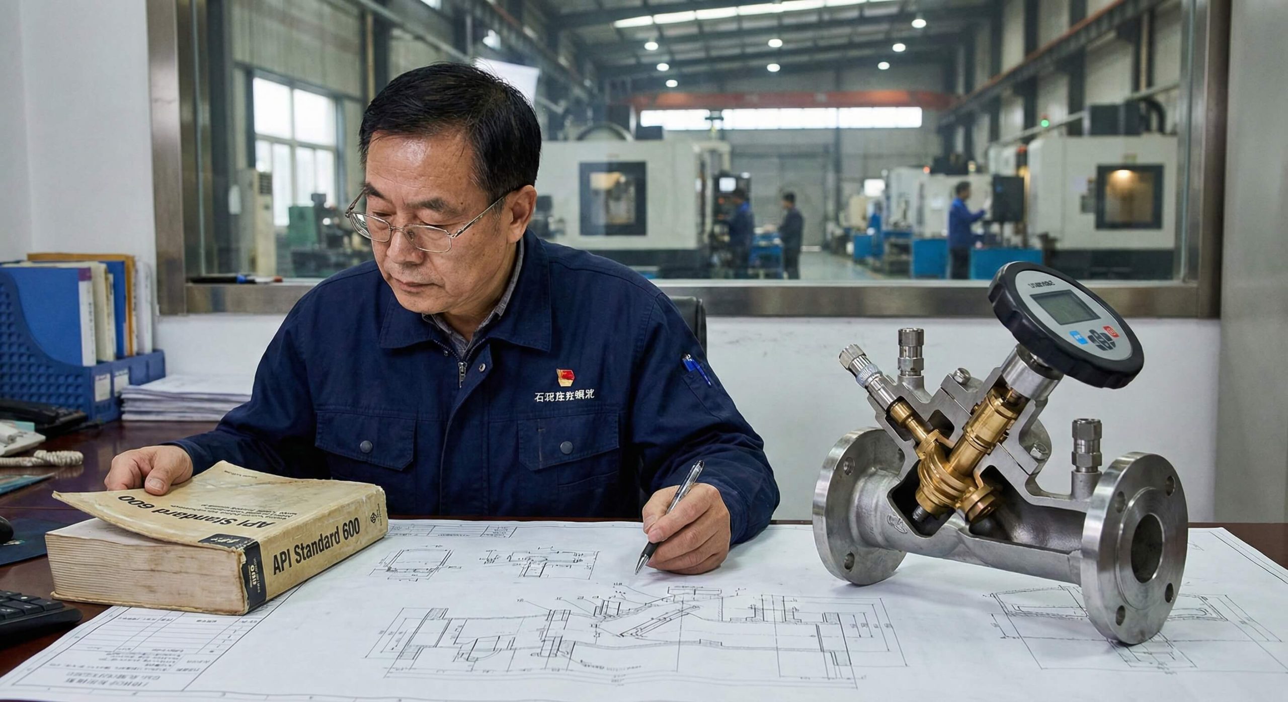
Installed RUITO DN25-DN100 static balancing valves at each equipment cooling supply with Kv selection calculated for 15 kPa target pressure drop. All valves fitted with calibrated measurement ports.

Measured Outcome

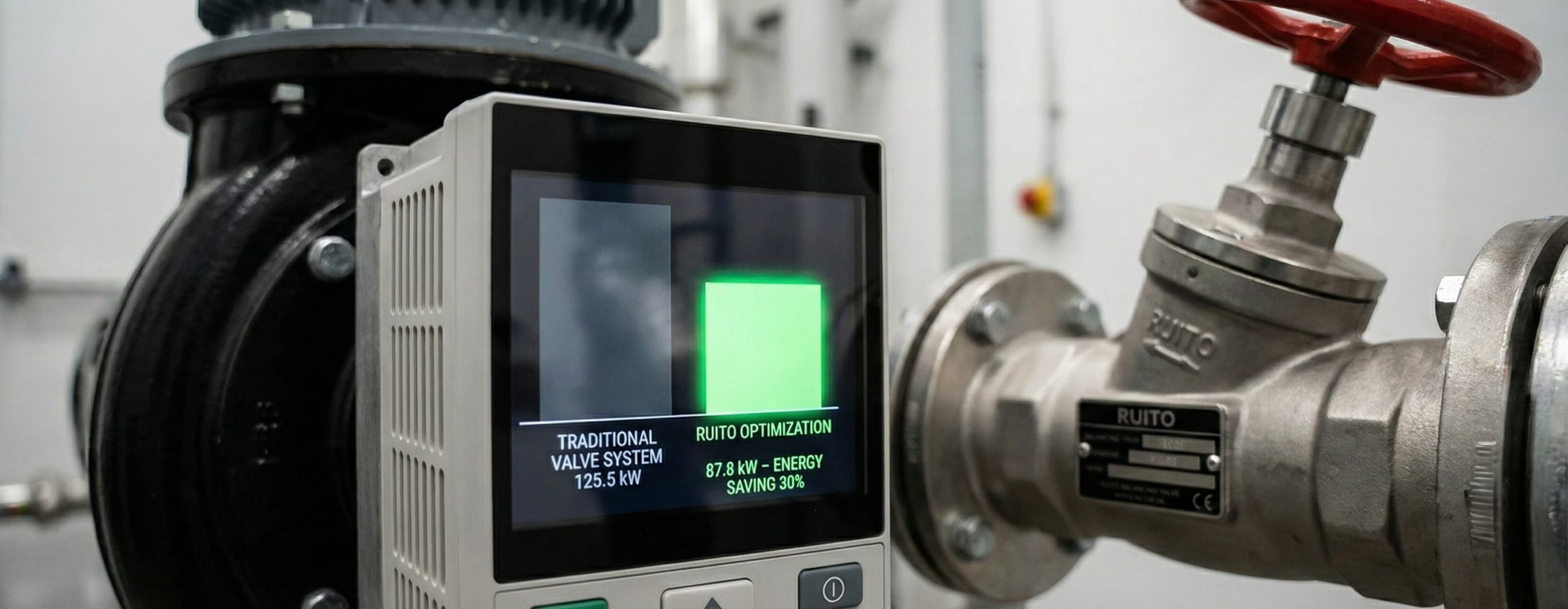
All process equipment achieved design flow within ±3% tolerance. Cooling water supply temperature increased from 6°C to 8°C without compromising process, reducing chiller energy by 18%.

District Heating Infrastructure

District Heating Network, Copenhagen

Project Background

Municipal thermal system serving 47 building connections across 2.4 km distribution network with substations ranging from 150 kW to 3.5 MW heating capacity.

Engineering Challenge

Buildings closest to heat plant consistently over-consumed flow allocation while distant buildings could not achieve design capacity. Manual throttling required continuous operator intervention.

Implemented Solution

Deployed RUITO DN50-DN150 dynamic balancing valves at all building heat exchanger primary connections. Valves configured for automatic differential pressure control.

Measured Outcome

Network hydraulic balance maintained automatically across full load range (20%-100%). All buildings achieved contract thermal delivery. Reduced annual maintenance labor by 140 hours.

Explore additional case studies relevant to your industry and application

Why RUITO - Optimized
Business meeting and partnership

Why Engineering Customers Choose RUITO Long-term

Risk mitigation mechanisms that protect procurement decisions and project timelines

Eliminating Risk

Delivery Schedule Uncertainty & Delays

Production Planning System

Common sizes maintained in stock for 2-week delivery. Production scheduling provides confirmed dates at quotation with contractual guarantees backed by penalty clauses.

Eliminating Risk

Technical Support Gaps in Design

Direct Engineer Access

Inquiries routed directly to HVAC application engineers. Calculations, Kvs verification, and system modeling provided within 24 hours.

Eliminating Risk

Batch Quality Variation & Defects

Traceability System

Every valve individually tested. Serial numbers link each unit to specific production batches, material certs, and test records for 5-year retention.

Eliminating Risk

Standard Catalog Capability Limits

Engineering Modification

In-house ability to create custom configurations, special seals for high-temp service, or modified Kvs values with low minimum order quantities.

Eliminating Risk

Communication & Response Delays

Dedicated Project Manager

Single point of contact assigned for major orders. Direct phone access with 4-hour response commitment during business hours.

Eliminating Risk

Regulatory Compliance Uncertainty

Active Certification Portfolio

Current CE, WRAS, and EN certificates provided at quotation. Certification roadmap maintained with advance notice of renewals.

Experience the difference systematic risk mitigation makes to project outcomes

Project Rhythm Support - Vertical Timeline

How We Support Your Project Rhythm

Coordinated response mechanisms aligned to critical project milestones and procurement workflows

Your Action

Need Sample Valves

Up to 3 sample units provided for qualified projects with confirmed specification requirements. Sample shipment initiated immediately upon approval.

5 Days
Your Action

Need Technical Validation

Valve selection calculations, Kvs verification, pressure drop analysis, and compatibility confirmation. Complex modeling available for major projects.

24 - 72 Hours
Your Action

Need Trial Order Processing

Initial orders accepted without minimum quantity requirement to enable contractor evaluation and commissioning validation. Production slot allocated.

1 Day Confirmation
Your Action

Need Phased Shipments

Single purchase order split into multiple shipments aligned to installation sequence. Consolidated invoicing provided at project completion.

2 Weeks Notice
Your Action

Need Emergency Replenishment

Expedited production and shipment for urgent replacements due to installation damage. Stock items dispatched within 48 hours.

48 Hours - 10 Days
Your Action

Need Documentation Package

Complete submittal package including technical datasheets, certification copies, material traceability, test reports, and installation guides.

3 Days

Discuss specific project timeline requirements and support coordination

RUITO Balancing Valve - Modules 16-18 Who Benefits - Optimized Persona Layout

Who Benefits from RUITO Balancing Valves

Specific customer roles and their critical requirements we address through technical capability and service infrastructure

Construction site planning

EPC Procurement Manager

Core Objective

Secure reliable valve supply that meets specifications without delivery delays or quality issues that disrupt critical path schedule.

Primary Risk

Supplier failures causing project delays trigger penalty clauses and damage contractor reputation with clients.

How RUITO Helps

Contractual delivery guarantees with penalty protection, complete certification package eliminating approval bottlenecks, and dedicated project manager.

Engineering project management

Engineering Project Manager

Core Objective

Deliver commissioned systems that pass performance testing and satisfy client acceptance criteria without extensive troubleshooting or rework.

Primary Risk

Valve performance shortfalls force repeated commissioning attempts consuming labor budget and extending handover timeline.

How RUITO Helps

Factory-calibrated measurement ports enable single-pass balancing, technical support during commissioning prevents troubleshooting delays.

Municipal infrastructure systems

Municipal Technical Director

Core Objective

Implement infrastructure systems achieving design performance across 20-30 year service life with minimal maintenance intervention.

Primary Risk

Inadequate component durability creates recurring maintenance costs and premature system replacement consuming limited capital budgets.

How RUITO Helps

Pressure-rated components for continuous duty cycles, material selection for corrosion resistance, and documented batch traceability.

OEM Manufacturing line

OEM Product Manager

Core Objective

Source components enabling product differentiation through superior performance while maintaining competitive manufacturing costs.

Primary Risk

Component suppliers unable to support custom specifications or scale production volume create product launch delays.

How RUITO Helps

Engineering modification capability for custom Kvs values, flexible order quantities supporting staged product rollout, and consistent batch quality.

Distribution warehouse inventory

Distribution Partner

Core Objective

Maintain inventory that meets contractor demand without excessive capital investment while providing technical support.

Primary Risk

Stock-outs lose immediate sales to competitors while excess inventory ties up working capital in slow-moving items.

How RUITO Helps

Predictable lead times enable just-in-time stocking, technical training materials support contractor education programs.

Identify how RUITO capabilities align with your specific role requirements

FAQ - Sidebar Layout

Frequently Asked Questions

Direct answers to common procurement, technical, and collaboration inquiries

Procurement & Pricing

Standard catalog items have no minimum order quantity for trial orders. For ongoing supply agreements, we recommend minimum 50-unit orders per size to optimize manufacturing efficiency and pricing. Custom specifications require minimum 50 units per configuration.

Pricing tiers based on total order value with volume discounts available for orders exceeding threshold quantities. Project quotations provided within 48 hours including detailed breakdowns by valve size and type. Annual volume commitments eligible for preferential pricing agreements.

Standard terms are 30% deposit with balance against copy of shipping documents. Established customers with approved credit references eligible for net 30 or net 60 terms. Letter of credit accepted for international orders above specified thresholds.

Delivery & Logistics

Stock items ship within 5-7 business days from order confirmation. Non-stock standard catalog valves require 15-20 business days for production. Custom specifications need 25-30 business days depending on modification complexity. Expedited production available for critical path items.

Yes, single purchase orders can be split into multiple shipments aligned to installation sequence. Phased deliveries coordinated with minimum 2-week notice per shipment. Storage at our facility available for completed production pending release authorization from project team.

Valves individually protected with plastic caps on ports and wrapped in anti-corrosion paper. Cartons reinforced for container shipping with moisture barriers. Palletized loads secured with strapping and stretch wrap. Special packaging for marine or tropical destinations available upon request.

Technical Support

Application engineers available to review system parameters and recommend appropriate valve types and sizes. Kvs calculations, pressure drop analysis, and authority verification provided within 24 hours for standard inquiries. Complex system modeling available for major projects requiring detailed hydraulic analysis.

Standard package includes dimensional drawings, Kvs curves, pressure test certificates, material traceability, and installation instructions. Certification copies and third-party test reports provided upon request. Custom submittal formatting available to match project specification requirements.

Remote technical support provided via phone and email during commissioning phase at no charge. Detailed balancing procedures and troubleshooting guides supplied with orders. For major projects, commissioning consultation available through coordination with local representatives or partners.

Collaboration & Partnership

Yes, in-house engineering team can develop custom valve configurations for OEM applications or special project requirements. Modifications include alternative seal materials, non-standard port arrangements, and custom Kvs values. Development typically requires minimum 50-100 unit annual volume commitment.

Factory visits welcomed for qualified procurement teams and certification auditors. Facility tours include production floor, testing stations, and quality control areas. Visit coordination requires 15-day advance notice. Pre-shipment inspection and witness testing also available for critical orders.

Standard warranty covers defects in materials and workmanship for 24 months from shipment date or 18 months from installation, whichever occurs first. Warranty claims supported by batch traceability records and test documentation. Extended warranty programs available for long-term supply agreements.

Engineering Support - Optimized Conversion Engineering Support - Value Driven Form Engineering Support - Value Driven Entry Engineering Support - Optimized UX Form
Modern engineering architecture background

Ready to Optimize Your Fluid Control System?

Connect with our engineering team for immediate technical support, valve selection, and project feasibility analysis.

Free Expert Valve Sizing

Receive accurate Kvs calculations and authority analysis to ensure optimal system performance.

24-Hour Response Guarantee

Get a complete technical proposal and competitive quotation within one business day.

Full Submittal Package

We provide all necessary datasheets, certificates, and drawings to speed up your approval process.

Get Free Technical Consultation

Fill in the details below to receive your custom valve selection report & quote.

Assigns your dedicated project engineer
Receives detailed quote & data package
Enables precise sizing and system optimization