
Uncalculated pressure loss in a butterfly valve can sabotage system efficiency and drive up operational costs. This leads to oversized pumps, wasted energy, and potential failure to meet project performance specifications, risking costly rework and reputational damage. When your fluid control system underperforms, the blame often falls on poor component selection, with the pneumatic butterfly valve being a frequent culprit. This article provides the technical data and formulas you need to accurately calculate and mitigate butterfly valve pressure loss, ensuring your system performs optimally from day one. You’ll gain the expertise to specify the right valve for your application.
What causes butterfly valve pressure loss?
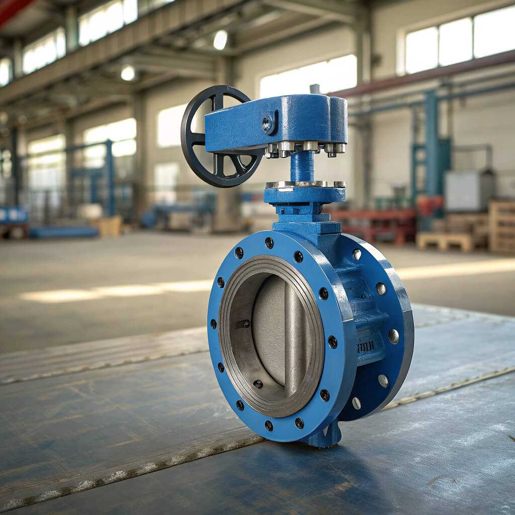
A pneumatic butterfly valve, by its nature, introduces a restriction into a piping system. This obstruction is the primary source of pressure loss, a critical factor in system design. The energy required to move fluid past the valve’s internal components is converted into low-level heat, resulting in a permanent pressure drop downstream. Inadequate accounting for this pressure loss forces pumps to work harder, consuming more energy and increasing the total cost of ownership. For any engineer, accurately predicting and managing this pressure drop is essential for designing an efficient and reliable fluid control system that meets its intended performance goals without unnecessary operational expense.
Understanding fluid dynamics
Fluid dynamics governs how liquids and gases behave in motion. In a pipe, fluid ideally moves in smooth, parallel layers, a state known as laminar flow. When an obstruction like a butterfly valve disc is introduced, this smooth flow is disrupted. The fluid must accelerate to get around the disc, and as it does, its pressure decreases. After passing the disc, the fluid decelerates and attempts to return to a normal flow pattern, but it never fully recovers its initial pressure. This unrecoverable energy loss is the pressure drop.
The role of the valve disc
The disc is the main component causing pressure loss in a butterfly valve. Even when fully open, the disc remains in the flow path, creating a permanent obstruction. The fluid must divide and flow around both sides of the disc. This action creates friction and turbulence, dissipating energy. The thickness, shape, and surface finish of the disc all contribute to the extent of this pressure loss. A thicker, less streamlined disc will cause a more significant pressure drop than a thin, aerodynamically profiled one. This is a key design consideration for any pneumatic butterfly valve.
How turbulence impacts efficiency
But what does this mean for you? Turbulence is chaotic, irregular fluid motion. As fluid passes the butterfly valve disc, eddies and vortices form in its wake. This turbulent flow consumes a significant amount of energy that would otherwise be used to move the fluid through the system. The higher the turbulence, the greater the pressure loss and the lower the overall system efficiency. A well-designed pneumatic butterfly valve minimizes turbulence by promoting a smoother flow path around the disc. The table below illustrates how the degree of opening directly correlates to turbulence and subsequent pressure loss.
| Valve Position | Flow Path Obstruction | Resulting Turbulence | Typical Pressure Loss |
|---|---|---|---|
| 90° (Fully Open) | Minimal (disc profile) | Low | Low |
| 60° (Partially Open) | Moderate | Medium | Medium |
| 30° (Partially Closed) | Significant | High | High |
| 0° (Fully Closed) | Complete | N/A (No Flow) | N/A (No Flow) |
The data shows a clear inverse relationship: as the valve closes, the obstruction increases, generating more turbulence and causing a greater pressure loss. Even a fully open butterfly valve presents a permanent, albeit small, obstruction that must be factored into system calculations.
A well-designed pneumatic butterfly valve minimizes turbulence to reduce pressure loss and improve system efficiency.
How do you measure butterfly valve flow?
To properly size and select a pneumatic butterfly valve, you need a standardized way to quantify its flow capacity. Simply looking at the pipe diameter isn’t enough, as the internal design of the valve significantly impacts how much fluid can pass through it at a given pressure. This is where flow coefficients come into play. These are standardized values that represent a valve’s efficiency in permitting fluid flow. They provide a reliable metric for comparing the performance of different valves and are essential for accurate system modeling. Using these coefficients allows you to calculate flow rates and pressure drops with confidence.
What are Cv and Kv flow coefficients?
The two most common flow coefficients are Cv and Kv. They measure the same fundamental property but use different units.
- Cv (Flow Coefficient): An imperial measurement defined as the volume of water in U.S. Gallons Per Minute (GPM) that will flow through a fully open valve with a pressure drop of 1 pound per square inch (PSI) at 60°F.
- Kv (Flow Factor): A metric measurement defined as the volume of water in cubic meters per hour (m³/h) that will flow through a fully open valve with a pressure drop of 1 bar at 20°C.
Both values are determined through physical testing by the manufacturer and are crucial for any pressure loss calculations.
The formula for calculating flow rate
Once you know the Cv value for your pneumatic butterfly valve, you can calculate the flow rate (Q) for any given pressure drop (ΔP). For liquids, the formula is straightforward:
Q = Cv * √(ΔP / SG)
Where:
Qis the flow rate in U.S. GPM.Cvis the valve’s flow coefficient.ΔPis the pressure drop across the valve in PSI.SGis the specific gravity of the fluid (water = 1.0).
This formula is the foundation for sizing a butterfly valve for a specific service condition.
Converting between Cv and Kv values
Here’s the bottom line: Since projects can be global, you’ll often need to convert between imperial (Cv) and metric (Kv) units. The conversion is a simple multiplication. The relationship is fixed and allows for easy comparison of valve datasheets from different regions. Using the wrong coefficient type will lead to significant errors in your pressure loss and flow calculations. The table below provides the direct conversion factors.
| To Convert From | To Convert To | Multiply By |
|---|---|---|
| Cv | Kv | 0.865 |
| Kv | Cv | 1.156 |
For example, a pneumatic butterfly valve with a Cv of 100 would have a Kv of 86.5 (100 * 0.865). Conversely, a valve with a Kv of 200 would have a Cv of 231.2 (200 * 1.156). This simple conversion ensures you’re using the correct values for your system’s unit requirements.
Always verify whether a datasheet lists Cv or Kv to avoid a 15% error in your flow and pressure loss calculations.
What affects a butterfly valve’s Cv value?
The Cv value of a pneumatic butterfly valve isn’t a single, static number. It’s a dynamic characteristic that changes dramatically based on the valve’s physical properties and its position. The most significant factor is the opening angle of the disc, which dictates the size of the flow path. However, other design elements, such as the thickness and shape of the disc, also play a crucial role in determining the valve’s overall flow capacity. Understanding these variables is key to predicting how a specific butterfly valve will perform within your system and helps you avoid under- or over-sizing, which can lead to control problems and inefficient operation.
How does the valve opening angle matter?
The relationship between the valve’s opening angle and its Cv is not linear. A butterfly valve exhibits what is known as an equal percentage flow characteristic. This means that for each increment of disc movement, the change in flow is a certain percentage of the current flow. The greatest change in Cv occurs between approximately 30 and 70 degrees of opening. The flow is very low when the valve is near-closed and changes very little when it is near-fully open (e.g., from 80° to 90°). This characteristic makes butterfly valves suitable for both on/off and throttling applications.
Disc thickness and shape considerations
The profile of the disc directly impacts the Cv value. A thin, streamlined disc presents less of an obstruction to the flow, minimizing turbulence and pressure loss, resulting in a higher Cv. In contrast, a thick, bulky disc creates more resistance and turbulence, leading to a lower Cv for the same nominal valve size. High-performance butterfly valves often feature contoured discs specifically engineered to maximize flow capacity. When selecting a pneumatic butterfly valve, examining the disc design on the technical datasheet can give you a strong indication of its flow efficiency.
Comparing Cv values at different angles
But what does this mean for you? The Cv value published on a datasheet is typically for the fully open (90°) position. For throttling or control applications, you must know the Cv at various opening angles. Manufacturers provide this data in tables or charts. As shown below, the Cv increases exponentially as the disc opens. This data is critical for calculating pressure loss and flow rates when the valve is used to regulate flow, not just for on/off service.
| Opening Angle | Typical Cv (% of Max) | Flow Characteristic |
|---|---|---|
| 10° | ~1% | Very Low Flow / Fine Control |
| 30° | ~15% | Throttling Range |
| 60° | ~60% | Throttling Range |
| 90° (Full) | 100% | Maximum Flow / On-Off |
Analyzing this table reveals that most of the flow control happens in the mid-range of the valve’s rotation. Using a butterfly valve for control below 20-30° opening is often ineffective due to the very low Cv and potential for cavitation and high wear on the valve components.
The Cv at your intended operating angle, not just the fully open value, is what determines the actual pressure loss in a throttling service.
How does butterfly valve design alter flow?
Not all pneumatic butterfly valves are created equal. The mechanical design of the valve body, disc, and seat has a profound effect on its flow characteristics and the resulting pressure loss. Designs range from simple concentric valves for basic applications to sophisticated triple-offset valves for severe service. Each design choice represents a trade-off between cost, longevity, sealing capability, and flow efficiency. Selecting the right design for your application is critical. Using a simple concentric valve where a high-performance one is needed can lead to premature failure and unacceptable pressure loss.
Concentric vs. eccentric designs
The primary distinction in butterfly valve design is the position of the disc in relation to the stem and body.
- Concentric (Zero Offset): The stem is centered in the valve bore, and the disc is centered on the stem. This simple, cost-effective design relies on the resilience of the rubber seat for sealing. However, the seat is in constant contact with the disc, causing friction and wear.
- Eccentric (Offset): The stem is offset from the center of the disc and/or the valve bore. Double-offset and triple-offset designs create a camming action, lifting the disc off the seat as it opens. This reduces friction, lowers operating torque, and extends seat life, especially in high-cycle or throttling applications. This improved action often results in a slightly better Cv.
Lined vs. high-performance valves
The type of service often dictates the valve’s construction.
- Lined Valves: These valves feature a liner (often PTFE or rubber) that forms the seat and isolates the valve body from the media. They are excellent for corrosive chemicals and sanitary applications. However, the liner can sometimes be thicker, slightly reducing the internal diameter and affecting the pressure loss characteristic.
- High-Performance Butterfly Valves (HPBVs): These are typically double-offset valves with more robust metal or reinforced seats. They are designed for higher pressures, higher temperatures, and more demanding throttling services. Their engineering often includes a more streamlined disc to improve flow and reduce pressure loss.
Material impact on flow characteristics
Here’s the bottom line: While the valve’s geometry is the primary driver of pressure loss, the material and its surface finish also contribute. Smoother surfaces create less friction, leading to a lower pressure drop. Rough cast surfaces or materials prone to scaling and corrosion can increase resistance over time, degrading the valve’s performance. The table below compares common materials and their general impact on flow.
| Material | Surface Finish | Friction Factor | Impact on Pressure Loss |
|---|---|---|---|
| PTFE (Lined) | Very Smooth | Very Low | Minimal |
| Stainless Steel (Polished) | Smooth | Low | Low |
| Carbon Steel (Standard) | Standard | Medium | Moderate |
| Ductile Iron (Unlined) | Relatively Rough | Higher | Increased |
The analysis shows that materials with a lower friction factor, such as PTFE or polished stainless steel, are superior for minimizing pressure loss. While the effect is smaller than that of the disc angle or valve type, it’s a contributing factor, especially in clean service or large-diameter lines where surface area is significant.
Selecting an offset design with a smooth, polished disc is the most effective way to minimize pressure loss and operating torque.
How do you calculate butterfly valve pressure drop?
Calculating the expected pressure drop across a pneumatic butterfly valve is a critical step in pump sizing and system hydraulic analysis. If you know the required flow rate and the valve’s Cv value at the intended operating angle, you can rearrange the standard flow formula to solve for pressure drop (ΔP). This calculation allows you to quantify the energy loss that the valve will introduce into your system. Failing to perform this calculation can lead to under-powered pumps that can’t meet flow requirements or over-powered pumps that waste electricity. An accurate calculation ensures the system is specified correctly from the start.
Key inputs for your calculation
To accurately calculate the pressure drop across your butterfly valve, you need three key pieces of information:
- Flow Rate (Q): The volume of fluid that must pass through the valve, typically in GPM (for imperial calculations) or m³/h (for metric). This is determined by the process requirements of your system.
- Valve Coefficient (Cv or Kv): The flow coefficient of the specific pneumatic butterfly valve you are considering, at the specific angle it will be operating. This value must be obtained from the manufacturer’s technical datasheet.
- Specific Gravity (SG): The ratio of the fluid’s density to the density of water. For water, the SG is 1.0. For other fluids, you will need to use the correct value.
A step-by-step pressure drop formula
The formula for calculating pressure drop (ΔP) is a simple algebraic rearrangement of the flow rate formula.
For imperial units (Q in GPM, ΔP in PSI):
ΔP = SG * (Q / Cv)²
For metric units (Q in m³/h, ΔP in bar):
ΔP = SG * (Q / Kv)²
First, divide the required flow rate (Q) by the valve’s flow coefficient (Cv or Kv). Second, square the result of that division. Finally, multiply that number by the specific gravity (SG) of the fluid to get your final pressure drop value.
Sample pressure drop calculations
But what does this mean for you? Let’s put this into practice. Imagine you need to pass 1,500 GPM of water (SG=1.0) through a pneumatic butterfly valve. You are considering two different valves. Valve A has a Cv of 2,000 at 90° open, while Valve B has a Cv of 2,500. The pressure drop calculation demonstrates the importance of selecting a valve with a higher Cv. The table below shows the results.
| Parameter | Valve A | Valve B |
|---|---|---|
| Flow Rate (Q) | 1,500 GPM | 1,500 GPM |
| Specific Gravity (SG) | 1.0 | 1.0 |
| Valve Coefficient (Cv) | 2,000 | 2,500 |
| Calculated Pressure Drop (ΔP) | 0.56 PSI | 0.36 PSI |
The calculation is ΔP = 1.0 * (1500 / Cv)². For Valve A, this is (1500/2000)² = 0.75² = 0.56 PSI. For Valve B, it’s (1500/2500)² = 0.6² = 0.36 PSI. Valve B, with its higher Cv, imposes nearly 36% less pressure loss on the system, which translates directly to energy savings over the life of the project.
A higher Cv value for a given flow rate will always result in a lower pressure loss, reducing pump energy consumption.
How do you select the right butterfly valve?
Selecting the correct pneumatic butterfly valve requires a careful balance of multiple factors. It’s not just about matching the pipe size. You must consider the required flow rate, the acceptable pressure loss, the fluid properties, and the control requirements of the application. The goal is to choose a valve that meets all performance criteria without being unnecessarily expensive or inefficient. An improperly specified valve can create control problems, cause excessive energy consumption, or fail prematurely. Making the right choice upfront is far less costly than correcting a mistake after installation.
Balancing flow needs and system pressure
The ideal pneumatic butterfly valve is one that can pass the required flow rate while creating an acceptable amount of pressure loss. You want the lowest possible pressure loss in on/off applications to maximize efficiency. In throttling applications, however, the valve must be able to create sufficient pressure drop to effectively regulate flow. This means the valve should typically be sized so that it operates somewhere between 30% and 80% open at the desired flow rate. This provides good control authority without excessive pressure loss.
Why over-sizing a valve is a mistake
A common error is to simply select a butterfly valve that matches the line size. This often results in an oversized valve. An oversized valve used for throttling will operate at a very small opening angle (e.g., less than 20% open) to achieve the desired flow rate. In this range, the flow characteristic is poor, making precise control very difficult. The high fluid velocity through the small opening can also cause cavitation, erosion, and vibration, leading to premature damage to the valve disc and seat. This dramatically shortens the valve’s service life and compromises system stability.
Checklist for proper valve specification
Here’s the bottom line: A systematic approach ensures you don’t miss any critical details when specifying your pneumatic butterfly valve. Use a checklist to gather all the necessary process data before consulting a manufacturer. This ensures you are comparing options accurately and selecting a valve that is fit for purpose, which is essential for avoiding project delays and performance issues. The table below serves as a basic specification checklist.
| Parameter | Data Required | Purpose |
|---|---|---|
| Fluid | Type, Temperature, Viscosity, SG | Material compatibility, pressure loss calculation |
| Flow | Min, Normal, Max Flow Rates (Q) | Sizing for control and max capacity |
| Pressure | Inlet Pressure, Allowable ΔP | System performance, pressure loss calculation |
| Function | On-Off or Throttling | Determines required valve characteristics |
| Line Size | Nominal Pipe Diameter | Initial sizing reference (not final selection) |
| Materials | Body, Disc, Seat Requirements | Chemical compatibility and longevity |
By completing this checklist, you provide a valve supplier with everything they need to recommend a pneumatic butterfly valve that is correctly sized and constructed for your specific application. This data-driven approach removes guesswork and prevents costly errors.
Proper valve sizing is about controlling the fluid, not just filling a space in the pipe.
With a clear understanding of pressure loss, flow coefficients, and valve design, you now have the knowledge to specify the correct pneumatic butterfly valve for your system. This expertise prevents the common pitfalls of oversizing and ensures your projects operate efficiently, reliably, and within budget.
RUITO: Engineering reliable fluid control solutions to guarantee the performance and longevity of your critical projects.
Ensure your system meets its performance specifications without risking costly energy waste. Contact the RUITO engineering team for a complimentary pressure loss analysis and receive a detailed valve recommendation, complete with technical datasheets and certification, within 48 hours.
Frequently Asked Questions
Q1: What is a typical Cv value for a butterfly valve?
A1: It varies greatly with size and design. For example, a 4-inch high-performance butterfly valve might have a Cv of around 800 when fully open, while a 12-inch valve could exceed a Cv of 10,000. Always refer to the manufacturer’s datasheet for the specific model.
Q2: Can I use a butterfly valve for throttling gas or steam?
A2: Yes, but with special considerations. High-performance double or triple-offset butterfly valves are often used. For gases, you must use specific compressible flow formulas. For steam, flashing and cavitation are major concerns, so proper sizing and material selection are critical.
Q3: How does pressure loss affect pump selection?
A3: The total pressure loss from all components in a system (pipes, fittings, and valves) determines the total dynamic head (TDH) the pump must overcome. Accurately calculating the butterfly valve’s pressure loss is essential for sizing a pump that can provide the required flow and pressure without being oversized and inefficient.
Q4: Why is a butterfly valve’s Cv not linear with its opening angle?
A4: The flow path around a circular disc inside a circular pipe does not increase linearly as the disc rotates. The area opens slowly at first, then rapidly through the mid-stroke (30°-70°), and then slowly again as it approaches fully open. This creates the characteristic “equal percentage” flow curve.
Q5: What happens if the pressure drop is too high across the valve?
A5: An excessively high pressure drop in liquids can lead to cavitation, where low-pressure voids form and then violently collapse, causing noise, vibration, and severe damage to the valve internals. It also represents significant wasted energy, increasing pump operational costs.