
Your current process relies on manual valve control, which is slow, inconsistent, and prone to human error. Imagine a critical batch being ruined because a valve wasn’t shut at the precise moment, or a safety protocol failing due to a slow manual response. By integrating a pneumatic actuator with a solenoid valve, you transform your standard butterfly valve into a responsive, automated control point that delivers the precision and reliability your system needs.
Core Components of the Butterfly Valve
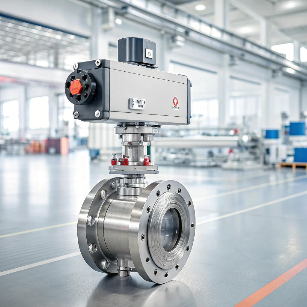
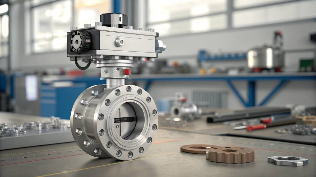
This automated assembly consists of three key parts working in perfect sync to control your process flow. The pneumatic actuator provides the muscle, the solenoid valve acts as the brain’s trigger, and the butterfly valve itself manages the media. Understanding how they interlink is crucial for appreciating their combined power.
The Pneumatic Actuator: Your Power Source
Here’s the deal: the pneumatic actuator is the engine that drives the entire operation. It uses the force of compressed air to generate powerful, swift rotational movement. This component is responsible for turning the abstract command from your control system into a physical action at the valve.
- Converts compressed air into mechanical quarter-turn motion.
- Provides high torque for reliably opening and closing the valve disc.
- Enables rapid actuation, often in less than a second.
What is the Solenoid Valve’s Role?
But what does it actually do? The solenoid valve is a compact, electrically controlled pilot valve that directs the flow of compressed air into the actuator. It acts as an intelligent switch, taking a low-power electrical signal from your PLC or control panel and using it to unleash the high-power pneumatic force needed to turn the valve.
- Acts as an electrical interface between your control system and the pneumatic actuator.
- Receives signals from your PLC, DCS, or a simple switch.
- Directs airflow to the correct ports on the actuator to either open or close the butterfly valve.
The Butterfly Valve Body & Disc
Now for the main event, the butterfly valve itself, which is where flow control physically happens. The body houses a central rotating disc that pivots to either allow flow or block it off completely. Its design is simple yet effective, providing a reliable seal when closed and minimal obstruction when open.
- Houses the rotating disc that directly regulates the flow of media.
- Features an internal liner or seat to create a bubble-tight seal.
- Connects directly into your process piping via flanges or wafer-style connections.
Key Takeaway: Understanding how the actuator, solenoid, and valve body work together is the first step to leveraging this technology. Each component plays a vital role in creating a fast, reliable, and automated flow control system you can count on.
| Component | Primary Function |
|---|---|
| Pneumatic Actuator | Provides the mechanical force for valve rotation. |
| Solenoid Valve | Electrically controls the air supply to the actuator. |
| Butterfly Valve Body | Contains the disc and seat to regulate media flow. |
This table clarifies how each component contributes to the assembly’s overall function, turning a simple signal into powerful action.
How Your Butterfly Valve Operates
The operational sequence of a pneumatically actuated butterfly valve is a model of electromechanical efficiency. It translates a simple electrical signal into immediate, decisive mechanical motion with just a few steps. This process ensures your valve responds instantly and predictably every single time.
What happens when the solenoid is energized?
This is where the magic happens: the entire sequence kicks off the moment an electrical signal reaches the solenoid. The solenoid coil creates a magnetic field, which moves a plunger inside the valve. This simple action opens an internal pathway, instantly releasing compressed air that has been waiting on standby.
- An electrical signal is sent to the solenoid from your control system.
- The energized solenoid opens a port, allowing compressed air to enter.
- This pressurized air is immediately directed toward the pneumatic actuator.
The Quarter-Turn Actuation
So, what’s next? The rush of compressed air enters the actuator’s chamber, where it exerts force against a piston or diaphragm. This linear force is ingeniously converted into rotary motion by an internal rack-and-pinion or scotch-yoke mechanism. This movement turns the valve stem exactly 90 degrees, moving the disc from fully open to fully closed, or vice versa.
- Pressurized air pushes a piston or diaphragm inside the actuator.
- This force is converted into powerful rotary motion.
- The valve stem rotates precisely 90 degrees to change the disc’s position.
Understanding Fail-Safe Mechanisms
But what if the power fails? This is where you choose your valve’s default behavior by selecting either a spring-return or double-acting actuator. Spring-return actuators use springs to force the valve to a pre-set “safe” position (open or closed) upon loss of air or power. Double-acting actuators require air to move in both directions and will simply stay in their last position.
- Fail-Close: The valve automatically closes on loss of power/air (most common for safety).
- Fail-Open: The valve automatically opens on loss of power/air.
- Fail-in-Place: The valve holds its last known position (used in double-acting actuators).
Key Takeaway: The operational sequence is elegantly simple, translating an electrical signal into immediate physical action. Choosing the right fail-safe mechanism ensures your system defaults to a safe state during an unexpected outage, protecting your process and personnel.
| Actuator Type | On Power/Air Loss | Best Use Case |
|---|---|---|
| Spring-Return | Fails Open or Fails Close | Critical safety applications like emergency shutdown systems. |
| Double-Acting | Fails in Place | Non-critical processes where holding position is acceptable. |
This comparison highlights the critical decision between actuator types based on your system’s safety requirements.
Benefits of This Automated Butterfly Valve
Upgrading to an automated butterfly valve assembly brings transformative benefits to your operation. You move from slow, inconsistent manual control to a system defined by speed, accuracy, and enhanced safety. These advantages directly impact your efficiency, product quality, and bottom line.
Achieving Precision and Repeatability
Think about this: automation removes the guesswork and human variability from your process. An automated butterfly valve opens and closes at the exact same speed and to the exact same degree every single time. This level of consistency is impossible to achieve manually, leading to superior product quality and less waste.
- Eliminates human error in valve timing and operation.
- Ensures consistent batching, mixing, and dosing processes.
- Integrates seamlessly with automated system recipes for flawless execution.
How it Enhances Operational Safety
You might be wondering how it improves safety. By allowing remote operation, you can control valves in hazardous or hard-to-reach areas from a secure control room. This eliminates the need for operators to expose themselves to dangerous chemicals, extreme temperatures, or confined spaces to manually actuate a valve.
- Allows remote operation, keeping personnel away from hazardous process areas.
- Enables rapid, sub-second emergency shutdowns with the push of a button.
- Reduces the risk of repetitive strain injuries associated with operating large manual valves.
Boosting Your System’s Efficiency
Here’s the bottom line: speed and reliability equal efficiency. Automated valves reduce process cycle times, minimize waste from spills or inaccurate flow control, and free up your skilled operators to focus on more complex, value-added tasks. Your entire operation becomes leaner and more productive.
- Drastically reduces process cycle times compared to manual operation.
- Minimizes product loss from over-fills or incorrect mixing.
- Frees up valuable operator time for monitoring and process optimization.
Key Takeaway: The upgrade to an automated butterfly valve is not just about convenience; it’s a strategic move. You gain a safer, more precise, and highly efficient operation that directly translates to a stronger bottom line and more reliable production outcomes.
| Benefit Category | Manual Control Drawback | Automated Valve Advantage |
|---|---|---|
| Precision | Inconsistent timing, variable flow | Sub-second, repeatable actuation |
| Safety | Operator exposure to hazards | Remote control from a safe location |
| Efficiency | Slow response, labor-intensive | Instant response, reduced labor costs |
This analysis shows the clear return on investment by contrasting the limitations of manual systems with the gains from automation.
Selecting the Right Butterfly Valve
Choosing the correct components for your automated butterfly valve assembly is critical for ensuring performance and longevity. A mistake in sizing, material selection, or actuator type can lead to system failure, leaks, and costly downtime. You must carefully match every part of the valve to your specific application requirements.
Do you know your size and pressure needs?
First things first, you must match the valve to your piping and process conditions. The valve’s nominal size must correspond to your pipe diameter, and its pressure rating must comfortably exceed the maximum operating pressure of your system. Don’t forget to also check that the valve’s temperature limits are suitable for your media.
- Match the valve size (e.g., 4-inch) directly to your pipe diameter.
- Verify the valve’s pressure rating (e.g., 150 PSI) is higher than your system’s maximum.
- Confirm the operating temperature range is compatible with your process.
A Guide to Material Compatibility
This part is crucial: the valve’s materials must be chemically compatible with the media flowing through it. An incorrect choice of seat or disc material can lead to rapid degradation, seal failure, and process contamination. Always consult a chemical compatibility chart to verify your selections.
- EPDM Seat: Excellent for water, glycols, and many general-purpose applications.
- Buna-N (Nitrile) Seat: The preferred choice for oils, fuels, and petroleum-based media.
- Stainless Steel Body/Disc: Necessary for corrosive media, sanitary applications, or high-purity systems.
Choosing Your Pneumatic Actuator
Ready for the final piece? The actuator must be sized to provide sufficient torque to overcome the forces of friction and flow, with a safety margin built in. You also need to select between a spring-return model for fail-safe applications or a double-acting model for non-critical functions.
- Spring-Return: Choose this for any application where the valve must default to open or closed on power loss.
- Double-Acting: A more economical choice when a fail-safe position is not required.
- Sizing: Ensure the actuator’s output torque exceeds the valve’s required torque by at least 25%.
Key Takeaway: Proper selection is non-negotiable for performance and longevity. By carefully matching the valve size, materials, and actuator type to your specific application, you ensure a reliable and leak-free installation that performs as expected from day one.
| Selection Factor | Key Question to Ask Yourself |
|---|---|
| Size & Ratings | Does the valve match my pipe size, pressure, and temp? |
| Materials | Are the body, disc, and seat compatible with my media? |
| Actuator & Solenoid | Do I need a fail-safe position? What is my control voltage? |
This decision matrix simplifies the selection process into three core areas of inquiry for a successful application.
Installing Your New Butterfly Valve
Proper installation is just as important as proper selection for ensuring your automated butterfly valve operates reliably. A rushed or incorrect installation can damage the valve seat, create leaks, and undermine the entire system’s integrity. Following a methodical process is the key to a successful startup.
Critical Pre-Installation Checks
Before you even touch a wrench, perform a thorough inspection of the assembly. Shipping and handling can sometimes cause unseen damage that will lead to failure down the line. A few moments of inspection can save you hours of troubleshooting later.
- Carefully inspect the valve, actuator, and solenoid for any signs of shipping damage.
- Cycle the valve once manually or with shop air to ensure the mechanism moves smoothly.
- Confirm you have the correct gaskets for your pipe flange type and process media.
How to Mount the Valve Correctly
Let’s get to it: mounting the valve between your pipe flanges requires care to avoid damaging the delicate seat. The valve must be perfectly centered and compressed evenly to create a lasting, leak-proof seal. Misalignment is a primary cause of premature valve failure.
- Position the valve with the disc slightly open during installation to prevent pinching the seat.
- Carefully align the valve body so it is perfectly centered between the two pipe flanges.
- Tighten the flange bolts gradually in a star or crisscross pattern to ensure even gasket pressure.
Connecting Air and Electrical Lines
The final step is connecting the brains and the muscle. You need to supply the solenoid with the correct electrical signal and the actuator with a clean, dry air supply at the right pressure. Incorrect connections can damage the components or cause erratic operation.
- Connect a clean, dry, properly regulated air supply to the solenoid’s input port.
- Run tubing from the solenoid’s output port(s) to the corresponding ports on the actuator.
- Wire the solenoid coil to your control system, double-checking to ensure the voltage matches.
Key Takeaway: A successful installation hinges on attention to detail. Following these steps for pre-inspection, mounting, and utility connections prevents common issues like seat damage and ensures your automated valve operates smoothly and reliably.
| Installation Phase | Critical Action | Why It’s Important |
|---|---|---|
| Pre-Installation | Cycle the valve before mounting. | Prevents installing a faulty unit and confirms smooth action. |
| Mounting | Tighten bolts in a star pattern. | Ensures even gasket compression and prevents flange leaks. |
| Connections | Use a clean, dry air supply. | Protects the actuator and solenoid internals from corrosion and debris. |
This procedural table highlights the most critical action in each phase to prevent common installation errors.
Maintaining Your Butterfly Valve System
To ensure your automated butterfly valve provides years of reliable service, a proactive maintenance plan is essential. Regular inspections and basic troubleshooting can help you catch small problems before they become major failures. This approach maximizes your return on investment and maintains system uptime.
Your Routine Inspection Checklist
Don’t set it and forget it. A simple, routine visual and auditory inspection can alert you to developing issues. Creating a checklist and performing it regularly is the easiest way to ensure the long-term health of your valve assembly.
- Check for any external leaks around the valve stem packing and the pipe flanges.
- Listen for the sound of audible air leaks from the actuator, tubing, or fittings.
- Visually inspect the entire assembly for signs of corrosion, physical damage, or loose connections.
Common Troubleshooting Scenarios
What if things go wrong? Most issues with these assemblies are straightforward to diagnose if you know what to look for. Before assuming a major failure, always check the simplest potential causes first, like the air and electrical supplies.
- Valve won’t cycle: Verify the air supply is on and at the correct pressure, then check for an electrical signal at the solenoid.
- Valve leaks when closed: The valve seat is likely worn, damaged, or incompatible with the media and needs replacement.
- Slow or sluggish operation: Look for low air pressure, a kinked air line, or an air leak in the system.
How to Extend Your Valve’s Lifespan
Want to maximize your investment? A few simple best practices can significantly extend the service life of your valve assembly. The most important factor is providing the actuator and solenoid with a clean, dry air supply, as moisture and debris are the leading causes of failure.
- Periodically cycle infrequently used valves (e.g., quarterly) to prevent the seat from sticking.
- Ensure your compressed air supply is filtered and dried to protect internal components.
- Adhere to a regular inspection schedule to catch and address issues early.
Key Takeaway: Proactive maintenance is far less costly than reactive repair. By implementing a simple schedule for inspection and knowing how to address common issues, you can significantly extend the service life of your assembly and ensure its continued reliability.
| Maintenance Task | Frequency | Purpose |
|---|---|---|
| Visual Inspection | Monthly | Catch external leaks, damage, and loose connections early. |
| Cycle Test | Quarterly | Ensure smooth operation and prevent the valve disc from seizing. |
| Air Supply Check | Continuously | Protect internal components from damaging moisture and debris. |
This schedule provides a simple yet effective framework for long-term valve care and reliability.
Conclusion
We’ve walked through how the frustrating inconsistencies of manual control lead to operational risks and inefficiencies. The clear solution is a pneumatic actuator-operated butterfly valve with a solenoid, which provides the precise, safe, and efficient automation modern systems demand. We specialize in providing expertly configured valve assemblies, tailored to your exact process requirements, ensuring you get the right solution the first time.
Contact our flow control experts today for a complimentary system consultation. Our vision is to pioneer intelligent flow control that builds a safer and more productive industrial future for everyone.
Frequently Asked Questions (FAQ)
- Q1: Can I install this butterfly valve in an outdoor environment?
Yes, but you must select components rated for your specific environment. Choose a NEMA 4 or IP65 rated solenoid enclosure to protect against water and dust, and consider actuator materials or coatings designed for UV and corrosion resistance. - Q2: What’s the best way to control the solenoid valve?
The best way is typically via a Programmable Logic Controller (PLC) or a Distributed Control System (DCS). This allows for full automation, integration with other process steps, and remote control from a central command station for maximum efficiency and safety. - Q3: How do I know if the actuator is sized correctly?
The actuator must be sized to provide enough torque to overcome the valve’s “breakaway” torque under full process pressure. We recommend consulting the valve manufacturer’s torque chart and adding a safety factor (typically 25%) to ensure reliable operation. - Q4: Can I use this butterfly valve for corrosive media?
Absolutely, provided you select the correct materials. For corrosive applications, you would typically specify a valve with a stainless steel (or more exotic alloy) body and disc, combined with a highly resistant seat material like PTFE (Teflon). - Q5: What’s the typical response time for this setup?
The response time is very fast, usually in the sub-second to a few seconds range. The exact time depends on the size of the actuator, the length and diameter of the air lines, and the air supply pressure, but it is significantly faster than any manual operation.