
Introduction: The High Cost of a Mismatched Valve
You’ve selected a butterfly valve that seems right, but your system is underperforming, with unstable flow rates and overworked pumps. A miscalculation in the valve’s flow coefficient (Cv) is often the hidden culprit, turning a simple component choice into a costly system-wide headache. This isn’t just an inconvenience; it means project delays, budget overruns, and potential equipment damage from noise, vibration, or even cavitation. Each day the system runs inefficiently, you’re wasting energy and money, and your professional credibility is on the line when a system you designed fails to deliver.
This guide provides the clarity you need to master butterfly valve Cv, from its core definition to its real-world impact on system performance. You’ll gain the confidence to select the precise valve for your application, ensuring optimal efficiency, reliability, and control every time.
1. What Defines Butterfly Valve Cv?
1.1 The Core Definition of Cv
The flow coefficient (Cv) is a standardized measure of a valve’s capacity, defined as the volume of water in GPM that flows through a fully open valve with a 1 psi pressure drop. You can think of it as the “width of the door” for fluid—a bigger door (higher Cv) lets more through with less effort. Here’s the deal: a higher Cv means lower resistance, which directly translates to less energy loss in your system.
- Flow Capacity: A direct measure of how much fluid a valve can pass.
- Efficiency: Higher Cv values indicate a more efficient flow path.
- Resistance: Inversely related to Cv; a higher Cv means lower resistance.
1.2 How Is Butterfly Valve Cv Measured?
Manufacturers determine a valve’s Cv through standardized laboratory testing, providing you with a reliable baseline for your calculations. This process ensures that you can accurately compare the performance of different valves under controlled conditions. The test establishes a valve’s maximum flow potential.
- A butterfly valve is installed in a dedicated test pipe section.
- Water at a standard temperature (60°F) is run through the system.
- The flow rate (Q) in GPM and the pressure drop (ΔP) in psi are measured.
- The Cv is then calculated using the industry-standard formula.
1.3 Why This Metric Matters to You
Understanding butterfly valve Cv is the foundation for designing efficient, stable, and cost-effective fluid control systems. It allows you to move beyond assumptions and base your valve selection on proven engineering principles. Properly applying this metric helps you avoid common pitfalls like excessive energy consumption and poor control.
- System Design: Prevents undersizing or oversizing of valves.
- Energy Efficiency: Minimizes pump workload and operational costs.
- Control Stability: Ensures the valve operates within its optimal range.
Key Takeaway: Mastering butterfly valve Cv isn’t just academic; it’s the foundation for designing efficient, stable, and cost-effective fluid control systems. Incorrectly applying this single metric can compromise your entire project, while mastering it ensures you deliver reliable performance.
| Feature | Low Cv Butterfly Valve | High Cv Butterfly Valve |
|---|---|---|
| Flow Capacity | Lower | Higher |
| Pressure Drop | Higher | Lower |
| Energy Use | Higher (pump works harder) | Lower (more efficient) |
| Best Use Case | Fine throttling/low flow | On/off or high-volume control |
This comparison shows that selecting the right Cv is a trade-off between control precision and energy efficiency.
2. How to Calculate Butterfly Valve Cv?
2.1 The Essential Cv Formula for Liquids
For liquid applications, you can determine the required Cv using a straightforward formula, which serves as your primary tool for valve sizing. The formula is Cv = Q / √(ΔP / SG), and you can also rearrange it to solve for the potential flow rate (Q) if you already know a valve’s Cv. This calculation is the first step toward ensuring your valve is correctly matched to your system’s demands.
- Cv: The Flow Coefficient you are solving for.
- Q: Your system’s required flow rate in GPM.
- ΔP: The allowable pressure drop across the valve in psi.
- SG: The Specific Gravity of your fluid (water = 1.0).
2.2 What about calculating for gases?
Calculating Cv for gases is more complex because their compressibility and temperature must be considered. Separate, more detailed formulas exist for sub-critical and critical (choked) flow conditions. But wait, there’s more. For any gas application, it is highly recommended that you consult the valve manufacturer’s technical data sheets or use their specialized sizing software to ensure accuracy.
- Liquid Calculations: Based on incompressible flow and a single formula.
- Gas Calculations: Depend on compressibility, temperature, and pressure conditions.
- Choked Flow: A condition where flow rate will not increase even if downstream pressure drops further.
2.3 Applying the formula in practice
To size a valve for a water pump line, you would plug your known values for the required flow rate (Q) and acceptable pressure drop (ΔP) into the formula. This calculation gives you the target Cv, which you then use to select a butterfly valve from a manufacturer’s catalog. Your goal is to find a valve that provides this target Cv within its ideal operating range.
- Define your system’s operational parameters (Q and ΔP).
- Calculate the required Cv value.
- Use the calculated Cv to choose a suitable valve model.
Key Takeaway: The Cv formula is your most powerful tool for initial valve sizing. By mastering its application for liquids and knowing when to seek expert data for gases, you can move from guesswork to precise engineering, ensuring the butterfly valve you choose is perfectly matched to your system’s demands.
| Parameter | Scenario A | Scenario B |
|---|---|---|
| Flow Rate (Q) | 500 GPM | 1000 GPM |
| Pressure Drop (ΔP) | 2 psi | 4 psi |
| Fluid (SG) | Water (1.0) | Light Oil (0.9) |
| Calculated Cv | ≈ 354 | ≈ 471 |
The required Cv changes significantly with flow rate and pressure, highlighting the need for specific calculations for each application.
3. Factors Affecting Butterfly Valve Cv
3.1 How does valve design impact Cv?
Not all butterfly valves are created equal, and the physical design of the valve itself has a major impact on its flow coefficient. A valve with a streamlined, thin disc profile will create less turbulence as fluid passes, resulting in a higher Cv. High-performance designs are specifically engineered to maximize flow efficiency.
- Concentric vs. Eccentric: Eccentric (offset) designs often provide a clearer flow path when open, boosting Cv by moving the disc out of the flow stream.
- Disc Geometry: High-performance butterfly valves have specially contoured discs to maximize flow and minimize pressure drop.
- Seat Material: While a minor factor, the seat can influence the valve’s internal profile and slightly affect flow characteristics.
3.2 What about fluid properties and their effects?
Your calculated Cv provides a baseline, but the properties of the fluid you are controlling will affect the valve’s real-world performance. Highly viscous fluids, like thick oils, increase friction and drag, effectively lowering the flow capacity compared to what the standard Cv value for water would suggest. Here’s where it gets tricky. You must adjust your expectations for the “personality” of your fluid, as temperature can also play a role by altering viscosity.
- Viscosity: Higher viscosity increases resistance and lowers the effective Cv.
- Specific Gravity: Directly used in the Cv formula and essential for non-water fluids.
- Temperature: Can change fluid viscosity, with higher temperatures often leading to better flow.
- Abrasives: The presence of solids can cause wear that degrades flow performance over time.
3.3 How do piping and positioning influence Cv?
A butterfly valve does not operate in a vacuum; its performance is influenced by the surrounding piping configuration. Nearby elbows, reducers, or other fittings can create turbulence that enters the valve, increasing pressure drop and lowering its effective Cv. As a best practice, you should install the valve with straight pipe runs of at least 5-10 pipe diameters upstream and downstream.
- Upstream Turbulence: Elbows or fittings close to the valve inlet can disrupt flow.
- Downstream Recovery: Sufficient straight pipe is needed for the flow to stabilize.
- Installation Orientation: Incorrect mounting can also negatively affect performance.
Key Takeaway: A butterfly valve’s stated Cv is its ideal performance. To achieve it, you must consider the complete system: the valve’s internal design, the nature of the fluid passing through it, and the surrounding pipe configuration. Ignoring these factors can lead to a significant gap between expected and actual performance.
| Factor | Impact on Cv | Your Action |
|---|---|---|
| Valve Design | High (Eccentric > Concentric) | Choose high-performance for critical flow |
| Fluid Viscosity | High (Higher viscosity = lower effective Cv) | De-rate Cv for viscous fluids |
| Piping | Medium (Turbulence lowers Cv) | Ensure straight pipe runs around the valve |
This table demonstrates that achieving the theoretical Cv requires a holistic view of the valve, media, and installation environment.
4. Sizing a Butterfly Valve with Cv
4.1 Why should you avoid oversized & undersized valves?
Improper valve sizing is one of the most common and costly mistakes in system design, leading to poor performance and premature failure. An undersized valve acts as a bottleneck, while an oversized valve offers poor control. Both scenarios result in operational inefficiencies and potential equipment damage.
- Undersized (Cv too low): This creates an excessive pressure drop, forcing pumps to work harder and wasting energy. It can starve the system of necessary flow and lead to cavitation.
- Oversized (Cv too high): Control becomes difficult because the valve operates mostly near its closed position. This leads to seat and disc wear, instability (chatter), and poor throttling response.
4.2 How do you match Cv to system requirements?
Your goal is not to find the valve with the highest possible Cv, but rather the valve with the right Cv for your specific application. The process begins with defining your system’s operational needs and then using the Cv calculation to select a valve that meets them. What’s the bottom line? You are looking for the “Goldilocks” valve—one that is perfectly sized to deliver stable and efficient control.
- First, determine your system’s required flow rate (Q) and acceptable pressure drop (ΔP).
- Next, use these values to calculate the target Cv for your application.
- Finally, consult a manufacturer’s chart to select a butterfly valve that provides this target Cv within its ideal control range (typically 30° to 70° open).
4.3 How does the opening angle change everything?
A butterfly valve’s Cv is not a single number but a curve that changes dynamically with the disc’s opening angle. The Cv is very low when the valve is nearly closed, rises sharply through the mid-range (30°-70°), and then flattens out as it approaches the fully open position. This is precisely why an oversized valve offers poor control—a tiny movement near the closed position results in a massive and unpredictable change in flow.
- 0°-30° Open: Low flow and high sensitivity, making control difficult.
- 30°-70° Open: The most stable and proportional control range.
- 70°-90° Open: Large changes in angle produce minimal changes in flow.
Key Takeaway: Proper butterfly valve sizing is a balancing act. You must use the calculated Cv to select a valve that will operate in its most stable and responsive range (the “sweet spot” of its opening angle), avoiding the twin pitfalls of system starvation and poor controllability.
| Disc Angle | Typical % of Max Cv | Control Characteristic |
|---|---|---|
| 10°-30° | 5-25% | Sensitive, prone to wear |
| 30°-70° | 25-85% | Optimal Control Range |
| 70°-90° | 85-100% | Low control, mostly for on/off |
The data confirms that for throttling applications, you should size the butterfly valve so its target Cv falls within the 30°-70° opening range.
5. Butterfly Valve Cv & System Performance
5.1 How do you link Cv to energy efficiency?
A butterfly valve’s Cv is directly tied to your system’s operational costs because pressure drop is a form of energy loss. A valve with a Cv that is too low for the required flow rate will create excessive resistance, forcing your pump to work harder and consume more electricity. Optimizing the valve selection based on Cv leads to a lower total cost of ownership.
- Reduced Load on Pumps: A correctly sized valve minimizes unnecessary back pressure.
- Lower Electricity Consumption: Less pump work means lower energy bills.
- Longer Component Lifespan: Reduced strain on pumps and motors extends their service life.
5.2 How can you prevent cavitation and noise?
Cavitation occurs when a severe pressure drop across the valve causes vapor bubbles to form and then violently collapse downstream. This destructive phenomenon creates loud noise, heavy vibration, and rapid erosion of the valve disc and body. Now, for the critical part. Selecting a butterfly valve with the wrong Cv for your system’s pressure conditions is a primary cause of cavitation, which can destroy a valve in a matter of weeks or months if not addressed.
- Loud Noise & Vibration: Clear signs of damaging cavitation.
- Rapid Erosion: The collapse of vapor bubbles can pit and wear away metal surfaces.
- System Instability: Cavitation leads to unpredictable flow and pressure fluctuations.
5.3 How do you ensure stable flow control?
The ultimate goal of any throttling system is to achieve stable, predictable, and repeatable flow control. A correctly sized butterfly valve, selected based on an accurate Cv calculation, provides smooth and proportional responses to actuator adjustments. An incorrectly sized valve, on the other hand, leads to “hunting” (oscillating back and forth), pressure surges, and an unstable process.
- Proportional Response: Flow changes predictably with valve position adjustments.
- System Stability: Avoids “hunting” and pressure surges.
- Process Reliability: Ensures your system delivers consistent results.
Key Takeaway: A butterfly valve’s Cv is not just a flow metric; it’s a direct predictor of your system’s health, efficiency, and reliability. Getting it right minimizes energy costs, protects equipment from destructive forces like cavitation, and delivers the stable performance you need.
| System Issue | Cv-Related Cause | Solution |
|---|---|---|
| High Energy Bills | Undersized valve (Cv too low) | Select valve with higher Cv to reduce ΔP |
| Valve Noise/Vibration | Incorrect Cv for pressure conditions | Recalculate Cv to avoid cavitation zone |
| Unstable Flow | Oversized valve (Cv too high) | Select smaller valve for better control |
This table serves as a diagnostic tool, linking common system problems back to specific errors in butterfly valve Cv selection.
6. Choosing the Right Butterfly Valve
6.1 What are concentric vs. eccentric designs?
The two main categories of butterfly valves are concentric and eccentric, and your choice depends on the demands of your application. A concentric design is simpler and more cost-effective for general service. An eccentric design provides superior performance for throttling, high-pressure, or abrasive services.
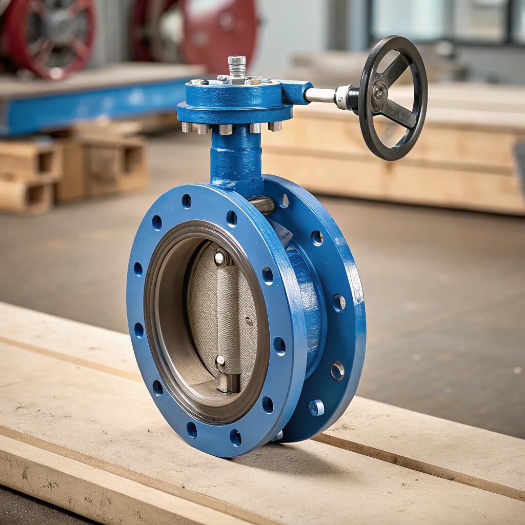
- Concentric Butterfly Valve: Features a stem centered in the disc, which is centered in the pipe bore. This simple design is best for on/off and low-pressure applications.
- Eccentric Butterfly Valve: The stem is offset from the disc’s center (single, double, or triple offset). This design allows the disc to swing clear of the seat upon opening, reducing wear and often providing a higher Cv.
6.2 When should you choose a high-performance valve?
A high-performance butterfly valve (HPBFV) is a type of double or triple offset valve engineered for more demanding conditions. You might be wondering: is it worth the extra cost? If your application requires precise control, tight shut-off, or longevity in a high-cycle environment, an HPBFV is the superior choice.
- Choose an HPBFV for higher pressure or temperature ratings.
- Select it for applications needing tight shut-off and precise throttling.
- Opt for it when you need a higher Cv than a standard concentric valve can offer.
- It provides better longevity in high-cycle or abrasive services.
6.3 How do you match materials to your application?
While materials don’t directly determine a valve’s Cv, selecting the right ones ensures the valve can perform reliably under your specific fluid conditions. The correct body, disc, and seat materials prevent corrosion and erosion that would otherwise degrade the valve’s internal surfaces. This degradation would alter its flow characteristics over time and lead to premature failure.
- Body: Ductile iron for water, carbon steel for higher pressures.
- Disc: Stainless steel for corrosion resistance, coated discs for abrasion.
- Seat: EPDM for water, PTFE for chemical compatibility.
Key Takeaway: Choosing the right butterfly valve goes beyond the Cv number. You must select the right type (concentric vs. eccentric) and materials for your specific operating conditions to ensure the valve not only meets your flow requirements but also delivers long-term, reliable service.
| Valve Type | Primary Use Case | Pressure/Temp | Cv Performance |
|---|---|---|---|
| Concentric | General Service, Water, HVAC | Low to Medium | Good |
| Double Offset | Throttling, Process Control | Medium to High | Better |
| Triple Offset | Critical Service, Steam, High Temp | High | Best |
This selection guide clarifies that as application demands increase, so does the need for more advanced butterfly valve designs to achieve optimal performance.
Conclusion: From Calculation to Confidence
We’ve shown that mastering butterfly valve Cv is the key to moving beyond risky guesswork in system design. By understanding how to calculate it and what factors influence it, you can avoid the common pitfalls of inefficiency, instability, and equipment failure. You don’t have to navigate these complex calculations alone; at RUITO, our engineering team specializes in fluid dynamics and partners with you to guarantee your project’s success. We provide the technical validation you need to build with confidence.
RUITO: Your trusted partner for high-reliability fluid control solutions, ensuring your projects succeed from specification to operation.
FAQ Section
Q1: How do I know if I’ve chosen a butterfly valve with the wrong Cv?
You’ll see clear signs in your system’s performance. An undersized valve will lead to a higher-than-expected pressure drop and insufficient flow. An oversized valve will cause unstable control, with the actuator constantly “hunting” for the right position and making noise.
Q2: Can I use the same butterfly valve Cv for water and other fluids?
No, not directly. The standard Cv is based on water. For any other fluid, you must account for its Specific Gravity (SG) in the formula, and for highly viscous fluids, you will also need to apply a correction factor.
Q3: Does a higher butterfly valve Cv always mean better performance?
Absolutely not. “Best” means “correctly matched” to the system’s needs. A butterfly valve with a Cv that is too high for the application will be oversized, leading to poor throttling control and accelerated wear.
Q4: At what opening angle is a butterfly valve most efficient for control?
The most effective and stable control range is typically between 30 and 70 degrees of opening. Below 30 degrees, control is too sensitive and prone to wear; above 70 degrees, a large change in angle produces only a small change in flow.
Q5: Can I increase the Cv of an existing butterfly valve?
No, you cannot. A valve’s Cv is an inherent characteristic of its physical design (size, disc shape, internal geometry). If you need a higher Cv, you must replace the valve with a different model or a larger size.