The flow coefficient, or CV, is the standard unit used to measure a valve’s capacity for allowing fluid to pass through its port at a specific resistance. Engineers and procurement officers often struggle with system inefficiencies and unexpected noise because they fail to properly size their equipment. Choosing a valve based solely on pipe diameter is a dangerous shortcut that often leads to an excessive pressure drop across butterfly valve components, causing cavitation and accelerated wear. Mastering the essentials of CV and the relationship between flow rate and resistance allows you to optimize your fluid control system for maximum longevity and cost-efficiency.
1. What is Butterfly Valve CV Flow Coefficient?
The CV value is the primary metric used to quantify a valve’s ability to allow fluid through its port. In practical terms, an inaccurate CV calculation directly results in a higher-than-expected pressure drop across butterfly valve installations, which disrupts the hydraulic balance of the entire line. Understanding this value is the first step toward achieving a stable process environment.
Defining the CV Formula for Industrial Valves
The standard CV formula for liquid flow is $CV = Q / \sqrt{\Delta P}$, where Q represents the flow rate in gallons per minute. This equation calculates the capacity based on a specific gravity of one, usually referencing water at 60°F.
Let’s break it down. To accurately determine the CV, you must consider:
- The required flow rate (GPM).
- The specific gravity of the media.
- The allowable pressure differential.
Why Flow Capacity Determines System Success
Properly rated CV values ensure that the pump does not have to overcome unnecessary resistance to move fluid. If the CV is too low, the energy consumption of the system increases dramatically to maintain the desired output.
Key Takeaway: Defining Flow Performance
The CV acts as a universal benchmark for efficiency, representing how many gallons per minute can pass through the valve with exactly a 1 PSI loss.
| Valve Size (Inch) | CV Value (90° Open) | Typical Application |
|---|---|---|
| 2″ (DN50) | 135 | Small Branch Lines |
| 6″ (DN150) | 1,579 | Process Water |
| 12″ (DN300) | 8,250 | Main Utility Lines |
The table above demonstrates that as the valve size increases, the flow capacity grows non-linearly to accommodate higher industrial demands.
2. Why is Pressure Drop Across Butterfly Valve Critical?
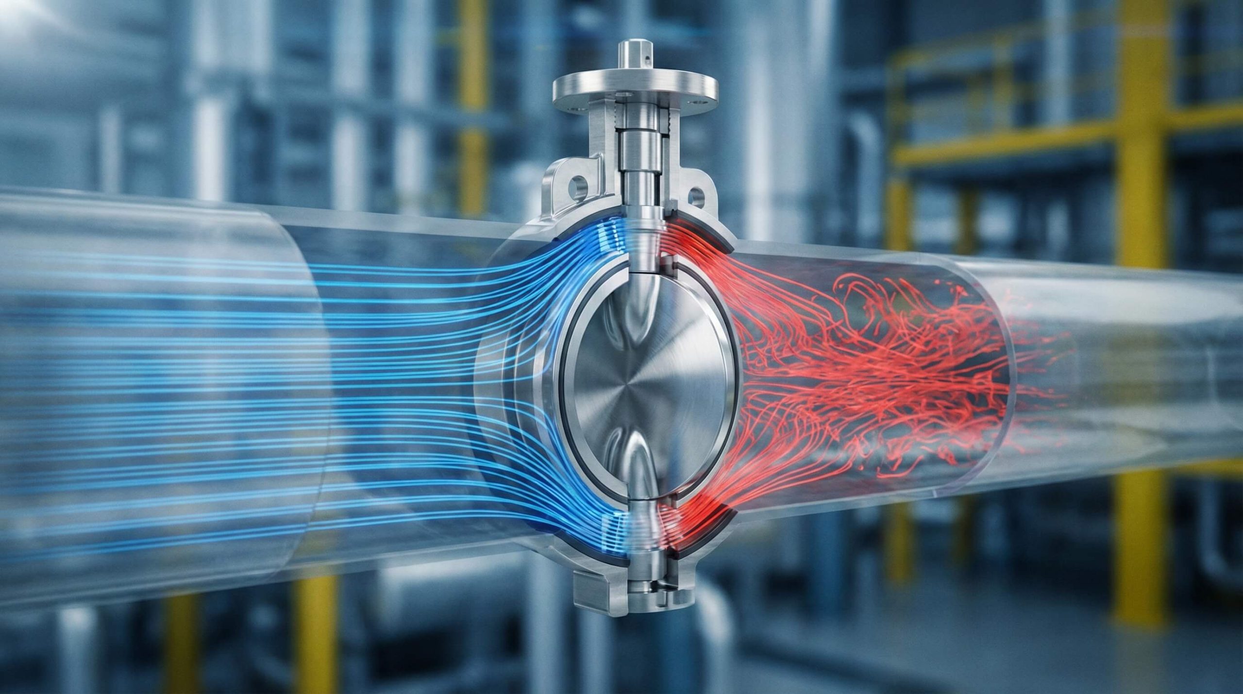
Managing the pressure drop across butterfly valve units is essential for protecting downstream equipment and maintaining pump efficiency. When the resistance is too high, the system consumes more energy and risks the onset of damaging turbulent flow. High differential pressure can also lead to mechanical vibration that loosens joints and damages seals.
The Correlation Between CV and Pressure Loss
There is an inverse relationship between the CV value and the pressure loss experienced during operation. A higher CV indicates a larger opening or more efficient internal geometry, which naturally lowers the resistance faced by the fluid.
But why does this matter so much? Because every PSI lost is money wasted in energy costs.
- Reduced pumping power requirements.
- Lower heat generation in the fluid.
- Minimized risk of structural vibration.
Impact of Resistance on Fluid Dynamics
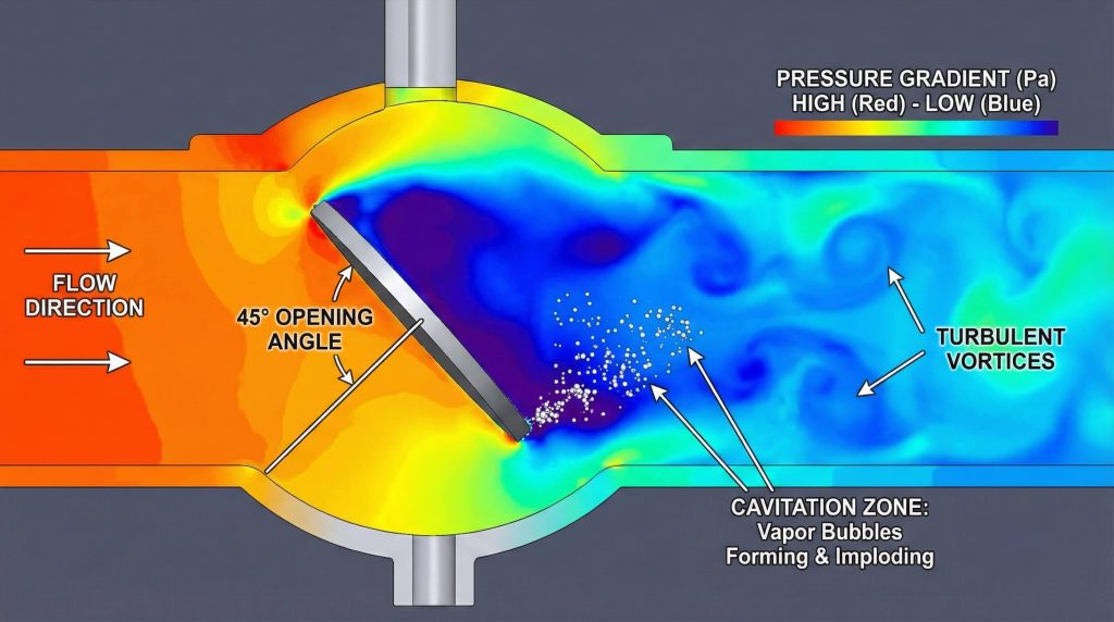
As fluid passes through a restriction, its velocity increases, which can lead to a drop in static pressure below the vapor pressure of the liquid. This scenario creates cavitation bubbles that can erode the valve disc and body over time.
Key Takeaway: Balancing Flow and Pressure
Properly balancing CV and pressure loss is the only way to ensure the long-term integrity of the piping network while minimizing operational energy expenditure.
| Opening Angle | CV Percentage | Impact on Pressure |
|---|---|---|
| 90° (Full) | 100% | Minimum Resistance |
| 60° | 45-55% | Moderate Loss |
| 30° | 10-15% | High Resistance |
This data shows that even moderate closing of the valve can lead to a significant spike in system resistance.
3. How Does Valve Design Influence CV Values?
Different internal geometries change how a medium navigates the disc, which affects the total pressure drop across butterfly valve assemblies. For instance, a high-performance design will offer different flow characteristics than a standard isolation valve. The thickness of the disc and the shape of the seat are primary factors in determining these values.
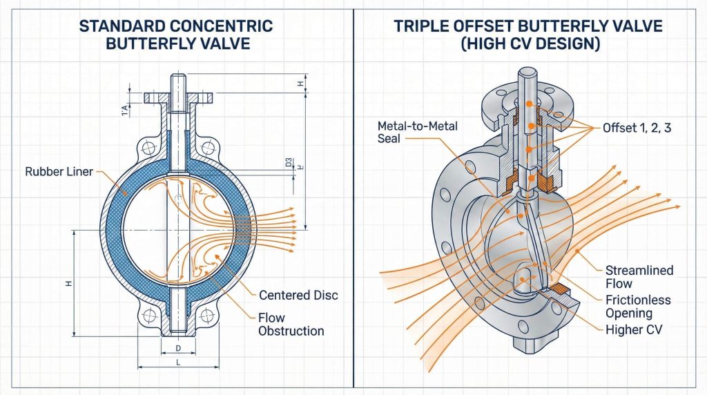
Concentric vs. Eccentric Flow Capabilities
Concentric valves have a disc centered in the bore, which can create more turbulence at the edges of the flow stream. In contrast, eccentric designs move the disc off-center to reduce seat contact and improve the flow path.
Here is the deal. Different designs are suited for different flow profiles:
- Concentric: Best for low-pressure water.
- Double Offset: High-pressure utility service.
- Triple Offset: Critical process applications.
Triple Offset Designs for High-Performance
Triple offset valves utilize a unique geometry that eliminates friction during the entire stroke. This design allows for a more streamlined flow path when fully open, resulting in a higher CV compared to many traditional rubber-lined valves.
Key Takeaway: Selecting Design Based on Flow
Matching the valve geometry to your specific flow requirements ensures that internal obstructions do not lead to unnecessary hydraulic losses.
| Design Type | Relative CV | Best Use Case |
|---|---|---|
| Concentric | Standard | Water Treatment |
| Double Offset | High | Steam/Chemicals |
| Triple Offset | Maximum | High-Temp Refining |
Advanced geometries provide superior flow paths, allowing for higher efficiency in demanding industrial environments.
4. Can Size Affect the Flow Coefficient Rating?
As the nominal diameter increases, the CV value grows exponentially, yet the relationship is rarely linear. A larger port generally reduces the pressure drop across butterfly valve setups, but over-sizing can lead to poor control at low opening angles. Selecting the correct size involves more than just matching the pipe diameter.
Scalability of CV in Large Diameter Valves
In large-diameter piping, the internal volume increases with the square of the radius, allowing for massive jumps in CV. However, the presence of the disc in the middle of the flow stream means that a butterfly valve will always have a lower CV than a full-bore valve of the same size.
Think about it. Choosing a 12-inch valve for a 10-inch flow requirement might seem safe, but it can cause issues:
- Poor throttling sensitivity.
- Increased installation costs.
- Potential for “seat hunt” during modulation.
Dimensional Accuracy and Port Geometry
Manufacturers must maintain strict tolerances on the internal diameter to ensure the published CV values are accurate. Even a few millimeters of deviation in the bore can lead to measurable differences in the actual flow capacity.
Key Takeaway: Sizing for Minimum Resistance
Sizing should be based on the required CV for the process, rather than the physical size of the existing pipe, to avoid the “bigger is always better” fallacy.
| Nominal Size | Typical CV Range | Velocity at Max CV |
|---|---|---|
| 4″ (DN100) | 600 – 800 | 12 ft/s |
| 8″ (DN200) | 3,100 – 3,500 | 15 ft/s |
| 16″ (DN400) | 14,000 – 16,000 | 18 ft/s |
Standardized sizing tables help engineers predict how much volume a system can handle without exceeding safe velocity limits.
5. How Do Materials Impact Internal Flow Efficiency?
The surface roughness of the disc and seat materials can influence the friction factor, contributing to the overall pressure drop across butterfly valve ports. While a polished stainless steel disc offers very low resistance, a rough cast iron disc might cause slight turbulence. Modern coatings are often applied to improve both corrosion resistance and flow efficiency.
Surface Friction and Disc Material Choices
Materials like PTFE or polished 316 stainless steel provide a slick surface that allows the fluid to glide past the disc. This reduced friction translates into a slightly higher CV compared to valves with traditional rubber or epoxy coatings.
Furthermore. The choice of material affects more than just durability:
- Stainless Steel: High flow, low friction.
- EPDM Lined: Standard flow, high sealing.
- Stellite Faced: High wear, moderate friction.
Sealing Ring Friction and Flow Obstruction
The way the seat interacts with the disc also plays a role in flow efficiency. In many resilient-seated valves, the seat protrudes slightly into the flow path, creating a minor obstruction that must be accounted for in CV calculations.
Key Takeaway: Material Selection and Smooth Flow
Using high-quality materials like stainless steel or PTFE-lined discs can improve the CV by reducing surface friction and preventing the buildup of scale.
| Disc Material | Surface Finish | CV Impact |
|---|---|---|
| Cast Iron | Rough/Epoxy | Baseline |
| 316 Stainless | Mirror Polished | +3-5% Efficiency |
| PTFE Coated | Low Friction | +2-4% Efficiency |
Investing in superior surface finishes can lead to long-term energy savings by reducing internal hydraulic drag.
6. What Happens During Non-Linear Flow Opening?

Butterfly valves are not linear-flow devices; their CV changes drastically as the disc moves from 0° to 90°. Operating a valve at a 30° angle creates a much higher pressure drop across butterfly valve discs compared to a fully open state, requiring careful actuator calibration. This non-linear characteristic is often described as “equal percentage.”
Opening Angles and Incremental CV Changes
At the start of the opening stroke, the CV increases very slowly because the disc is still mostly blocking the path. As the valve nears the fully open position, the CV increases rapidly, which can make fine control difficult in the last 20% of the stroke.
Wait, there’s more. The control “sweet spot” is typically found in the middle of the stroke:
- 0° – 30°: Poor control, high stress.
- 30° – 70°: Ideal control range.
- 70° – 90°: Maximum flow, low control.
Throttling Characteristics at Low Percentages
When used for throttling, the valve must be sized so that the normal operating flow occurs within the 30° to 70° range. Operating below 30° can cause high-velocity “jetting” that erodes the seat and creates excessive noise.
Key Takeaway: Optimizing Opening for Efficiency
Understanding the CV curve allows you to select an actuator and valve combination that maintains stability and efficiency throughout the required operating range.
| Degrees Open | % of Max CV | Control Quality |
|---|---|---|
| 20° | 5% | Very Poor |
| 50° | 35% | Excellent |
| 80° | 85% | Moderate |
The inherent flow characteristic of a butterfly valve requires careful sizing to ensure the process remains controllable and efficient.
7. Does Fluid Viscosity Alter Expected CV Results?
Calculations for water are the industry standard, but thicker fluids will increase the pressure drop across butterfly valve internals. If your system handles oils, slurries, or polymers, you must adjust your CV requirements. Viscosity creates internal friction within the fluid itself, making it harder to move through the restricted area of the valve.
Correcting Flow Math for Specific Gravity
The specific gravity of the media must be included in the CV formula ($CV = Q \times \sqrt{SG / \Delta P}$). Fluids heavier than water will require a larger valve (higher CV) to achieve the same flow rate at the same pressure loss.
Actually, there’s a catch. Viscosity correction is required when the fluid is significantly thicker than water:
- Light Oils: Minimal correction needed.
- Crude Oil: Moderate correction required.
- Molasses/Slurries: Heavy correction necessary.
Handling Slurries and Heavy Industrial Fluids
In slurry applications, the solids content can also physically obstruct parts of the flow path. This effectively reduces the usable CV and increases the wear on the disc and seat due to the higher velocities required.
Key Takeaway: Adapting CV for Diverse Media
Never assume water-based CV charts apply to all fluids; always apply viscosity and specific gravity correction factors to prevent system under-performance.
| Fluid Type | Specific Gravity | CV Adjustment |
|---|---|---|
| Water | 1.0 | 0% (Standard) |
| Diesel Fuel | 0.85 | -15% Required |
| Concentrated Acid | 1.8 | +80% Required |
Fluid density and viscosity are critical variables that can render standard manufacturer charts inaccurate if not properly adjusted.
8. How to Calculate Butterfly Valve Sizing Correctly?
Precision in sizing ensures that the pressure drop across butterfly valve components remains within the manufacturer’s recommended limits. Using the standard formula is the first step in avoiding the procurement of incompatible hardware. You must gather all process parameters, including maximum and minimum flow rates, before starting the calculation.
Practical Step-by-Step CV Calculation Guide
Start by identifying the maximum flow rate your system needs to handle. Then, determine the maximum allowable pressure drop that your pumps can support without failing or losing efficiency.
It gets better. Following a structured process prevents sizing errors:
- Define the media properties.
- Calculate the required CV for peak flow.
- Verify the CV at the minimum expected flow.
Using Manufacturers Data for Precision
Once you have your calculated CV, compare it to the manufacturer’s published tables. It is common practice to select a valve with a CV that is roughly 1.5 to 2 times the calculated requirement to provide a safety margin and better control.
Key Takeaway: Ensuring Exact Component Fit
The final selection must be verified against traceable test reports to ensure that the physical valve will perform exactly as the theoretical math suggests.
| Step | Action | Objective |
|---|---|---|
| 1 | Define GPM & SG | Establish baseline needs |
| 2 | Set Max Allowable ΔP | Protect pump efficiency |
| 3 | Apply CV Formula | Determine target capacity |
Correct sizing is a technical process that eliminates guesswork and ensures the safety and performance of the entire fluid network.
9. Why Do Mismatched CV Values Cause Failures?
If the CV is too low for the application, the resulting high-velocity pressure drop across butterfly valve seats will trigger cavitation. This phenomenon creates vapor bubbles that implode, pitting the metal and causing rapid degradation of the valve. Conversely, a CV that is too high can lead to “hunting,” where the actuator cannot find a stable position.
Risks of Cavitation and Flashing Damage
Cavitation is the most common cause of premature valve failure in high-pressure systems. The intense energy released during bubble implosion can eat through stainless steel discs in a matter of weeks, leading to total system failure.
Make no mistake. The consequences of poor sizing are expensive:
- Constant seat replacement costs.
- Unplanned system downtime.
- Severe damage to downstream piping.
Excessive Noise and Vibrational Stress
A mismatched valve often produces a high-pitched scream or a low-frequency rumble. This noise is a symptom of turbulent energy that is physically shaking the valve and its associated piping, leading to fatigue cracks.
Key Takeaway: Preventing Premature Valve Wear
Accurate CV selection is the most effective way to prevent cavitation and vibration, directly impacting the long-term ROI and safety of the plant.
| Failure Mode | Root Cause | Symptom |
|---|---|---|
| Cavitation | CV Too Low | Pitting on Disc |
| Hunting | CV Too High | Rapid Actuator Wear |
| Jetting | Poor Throttling | Seat Erosion |
Properly matched valves operate quietly and reliably, whereas mismatched components act as a bottleneck that degrades the entire system.
10. Where Can I Find Reliable Technical Valve Data?
Accessing accurate CV tables is critical for any project to ensure the predicted pressure drop across butterfly valve installations is verified before commissioning. High-quality manufacturers provide comprehensive QA dossiers that include torque and flow data. You should always look for data that has been verified by third-party laboratories.
Integrating Standards into Procurement
When writing specifications, insist on valves that meet international standards like API or ISO. These standards ensure that the flow data provided is consistent across different brands and batches.
In short. Quality documentation is your best insurance policy:
- Request certified flow test reports.
- Verify material certificates (MTRs).
- Check for compliance with industry standards.
Accessing Traceable Manufacturer Documentation
Reliable manufacturers offer online calculators and downloadable PDF charts that show CV values at every 10 degrees of opening. This level of detail is necessary for engineering teams to program control systems and PLC logic accurately.
Key Takeaway: Leveraging Expert Technical Support
Collaborating with a certified manufacturer ensures that you have access to the engineering expertise needed to solve complex flow challenges.
| Document Type | Importance | Content |
|---|---|---|
| CV Chart | Critical | Flow vs. Opening Angle |
| Torque Table | High | Actuator Sizing Needs |
| MTR | Essential | Material Chemistry |
Transparent data and expert support are the final pieces of the puzzle when designing an efficient and reliable fluid control system.
FAQ
- Can I use a butterfly valve for high-precision throttling?
Yes, but it is most effective between 30° and 70° opening because the flow characteristics are most stable and predictable within this range. - What’s the best way to reduce noise in a high-flow system?
You should select a valve with a higher CV to reduce the fluid velocity and minimize the pressure drop that causes turbulent noise. - Can I replace a gate valve with a butterfly valve to save space?
Yes, provided you verify that the butterfly valve’s CV is sufficient to match the flow capacity previously provided by the gate valve. - What’s the best material for abrasive slurry flow?
Ductile iron with a reinforced elastomer seat or a hardened disc is recommended to maintain a stable CV while resisting physical erosion. - Can I calculate CV without knowing the specific gravity?
You can only do this for water where the specific gravity is exactly one; for any other fluid, your result will be inaccurate.
Conclusion
Understanding CV is more than a mathematical exercise; it is a fundamental requirement for system safety and efficiency. By accurately predicting the pressure drop across butterfly valve units, engineers can prevent cavitation and extend the service life of their fluid control networks. Always consult with a technical expert to verify your flow calculations against certified test data. To ensure your system is equipped with the most efficient hardware, contact us today for a professional sizing consultation.