
The pressure drop coefficient K is a dimensionless value quantifying the permanent head loss of a fluid passing through specific piping components. Piping engineers often face massive energy losses when fluid systems lack precise resistance calculations. These inaccuracies lead toward undersized pumps or excessive vibration within expensive mechanical infrastructure. Mastering the butterfly valve k factor provides a robust framework for predicting hydraulic performance while maintaining system integrity. By applying empirical data from standardized resistance coefficients, you eliminate guesswork during industrial facility design.
1. What defines the butterfly valve k factor?
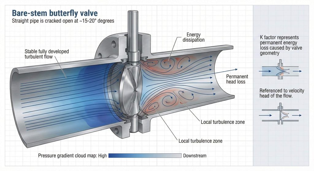
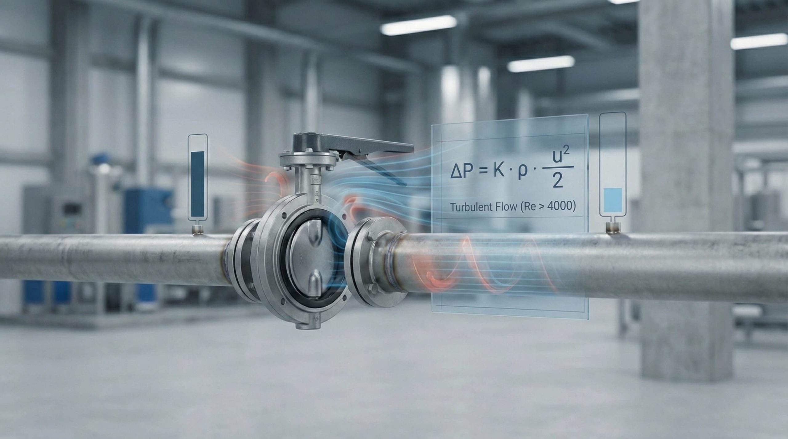
Selecting a bare shaft butterfly valve requires understanding how internal obstructions convert kinetic energy into heat or noise. By utilizing the butterfly valve k factor, you determine exact pressure differentials across various system configurations. These values assume fully developed turbulent flow where Reynolds numbers stay above 4000 for reliable modeling. Internal geometry creates micro-turbulence zones that elevate resistance profiles significantly during high-velocity operations.
Theoretical resistance logic
Here’s the deal. Designers use this coefficient to standardize losses relative to the velocity head of the medium moving through the pipe. This method ensures that the friction profile remains accurate during peak demand periods.
| Flow Characteristic | Value Range | Status |
|---|---|---|
| Reynolds Number | > 4000 | Turbulent |
| Resistance Type | Dimensionless | Static |
| Energy Loss | Permanent | High |
This data confirms that shape-dependent resistance dominates energy loss in high-velocity piping networks.
Key Takeaway: Understanding the K factor is the primary step for calculating total system resistance and specifying correct pump requirements.
2. How to calculate butterfly valve k factor?
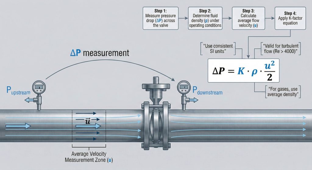
Every bare shaft butterfly valve installation depends on a fundamental relationship relating total pressure drop against fluid density and average flow velocity squared. Accuracy hinges upon maintaining consistent units like Pascals or bar across all analytical segments of your project. Gas density fluctuations require you to utilize average density values between inlet and outlet points for compressible media. High pressure drops necessitate breaking models into smaller sections to keep calculations precise.
The fundamental pressure formula
You might be wondering… How does this formula align with basic kinetic energy principles? Dividing the product of K, density, and velocity squared by two provides the exact pressure dissipation in SI units.
| Variable | Symbol | SI Unit |
|---|---|---|
| Pressure Drop | ΔP | Pa |
| Fluid Density | ρ | kg/m³ |
| Flow Velocity | u | m/s |
This mathematical framework allows you to predict friction losses across any industrial fluid transport system regardless of complexity.
Key Takeaway: Calculating pressure drop with the K factor requires accurate input data regarding fluid velocity and local density conditions.
3. Why does angle impact butterfly valve k factor?
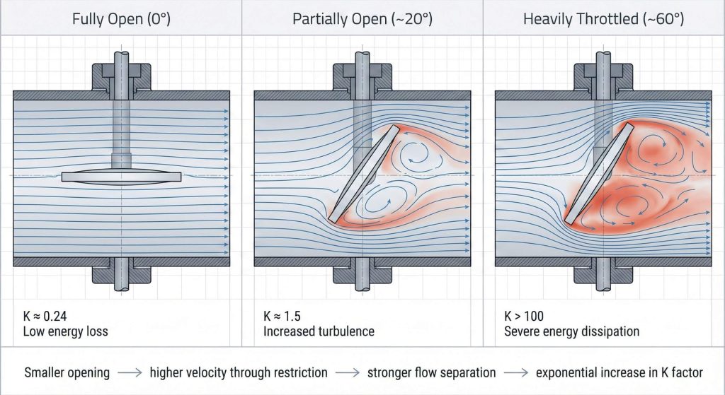
Adjusting a bare shaft butterfly valve manually or via actuator changes the effective opening area available for fluid passage. As the disc closes, the butterfly valve k factor climbs exponentially due to increased flow restriction and localized vortex generation. Even a minor ten-degree shift can double the resistance coefficient because of the massive turbulence generated behind the disc edge. This relationship remains critical when utilizing specialized throttling devices in high-pressure lines.
Impact of disc position
But here’s the kicker… A disc at a 60-degree angle can reach a resistance value over one hundred units. This massive increase in the coefficient consumes kinetic energy that would otherwise maintain downstream system pressure.
| Disc Angle | Position | K Factor |
|---|---|---|
| 0° | Fully Open | 0.24 |
| 20° | Partial Throttling | 1.54 |
| 60° | Heavy Restriction | 118.0 |
Small adjustments in the disc angle lead to significant shifts in the energy efficiency of the entire piping network.
Key Takeaway: The coefficient is highly sensitive to the disc angle, requiring you to select valves that operate in efficient ranges.
4. Is the butterfly valve k factor always constant?
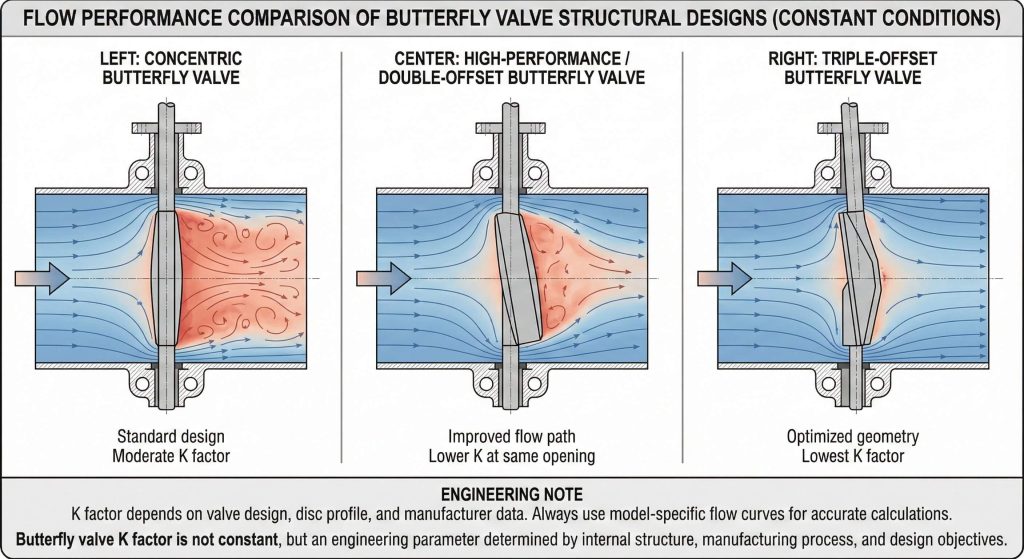
The bare shaft butterfly valve represents a unique challenge because its resistance isn’t a single static number across all manufacturers. High-performance discs with streamlined profiles offer significantly lower resistance than thick, standard-duty versions used in generic applications. You must request specific flow curves for your exact model to ensure your hydraulic calculations match the hardware. Design variations like offset discs change how fluid wraps around internal seals during high-velocity transit.
Design variations and performance
What’s the real story? Concentric discs create symmetrical turbulence patterns that affect pressure recovery differently than high-performance triple-offset designs. Choosing the right geometry can reduce your operational electricity costs for pumping over the facility lifecycle.
| Design Type | Efficiency | Typical Usage |
|---|---|---|
| Streamlined Disc | Superior | High Flow |
| Standard Duty | Moderate | Utilities |
| Lined Body | Variable | Corrosive Media |
Consistent monitoring of manufacturer-specific data prevents the common pitfall of under-performing fluid transport systems in industrial settings.
Key Takeaway: Prioritize streamlined disc designs and specific manufacturer data to maximize the energy efficiency of your fluid systems.
5. Can geometry change butterfly valve k factor?
If the bare shaft butterfly valve diameter does not match the pipe, additional entrance and exit losses alter the butterfly valve k factor. Internal body contours dictate the path fluid travels and how much kinetic energy is converted into turbulent eddies. Sudden contractions accelerate fluid rapidly through small orifices while expansions cause energy-dissipating separation zones. Smooth transitions and venturi-style body designs help maintain the momentum of the media during transport.
Influence of port transitions
Ready for the good part? You can mitigate these geometric losses by selecting valves with smooth internal passages that align perfectly with your piping schedule. Proper alignment prevents the secondary turbulence that often plagues poorly installed industrial assemblies.
| Feature Type | K Factor Impact | Primary Cause |
|---|---|---|
| Sharp Edge | High Increase | Flow Separation |
| Radius Entry | Significant Reduction | Streamlining |
| Misalignment | Moderate Increase | Secondary Vortex |
Minimizing sharp internal transitions is the most effective way to keep your total system resistance within acceptable project limits.
Key Takeaway: Internal geometry is a dominant factor in determining resistance, making port alignment critical for overall system health.
6. Does a globe valve exceed butterfly valve k factor?
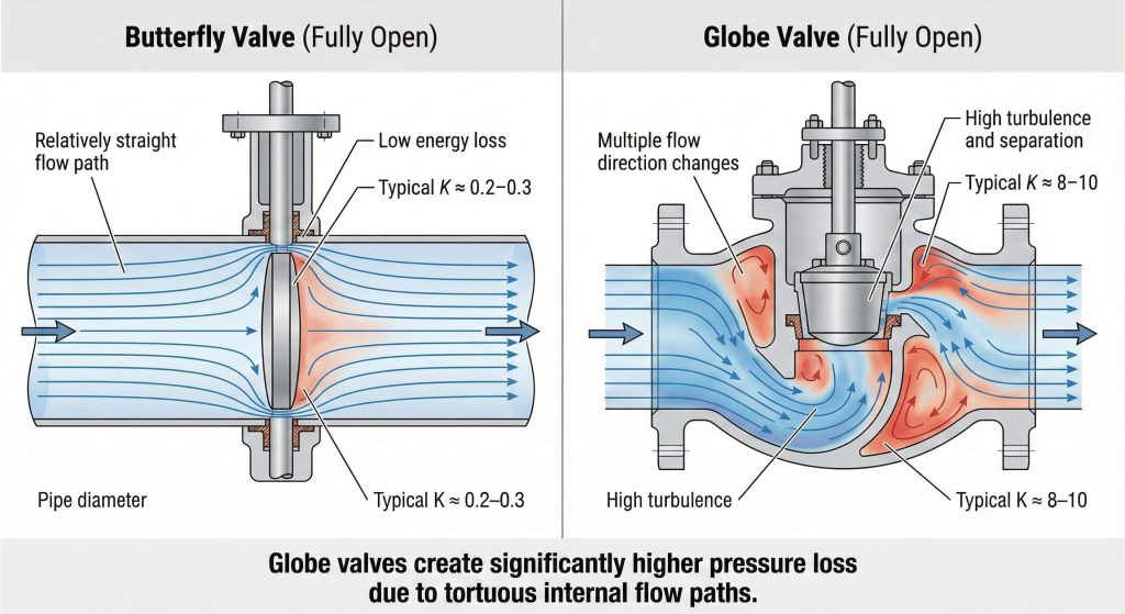
Integrating a bare shaft butterfly valve into a system that uses globe valves requires balancing drastically different resistance levels. Globe valves are notorious for high resistance because the fluid must change direction multiple times to pass the seat. Each 90-degree turn inside the body consumes kinetic energy while converting it into a measurable pressure drop. While butterfly designs offer very low resistance, open globe models often exceed a coefficient of nine.
The tortuous flow path
This is where it gets interesting… Fluid enters the valve body and must turn twice before exiting the assembly completely. This path makes them excellent for regulation but highly inefficient for high-volume bulk fluid transport.
| Valve Category | Open K Factor | Efficiency Rank |
|---|---|---|
| Butterfly | 0.24 | 2nd |
| Gate | 0.17 | 1st |
| Globe | 9.00 | 4th |
Choosing a butterfly valve over a globe valve can reduce localized pressure loss by over ninety percent in isolation applications.
Key Takeaway: Globe valves provide the highest resistance among standard valves and should be limited to precision regulation tasks.
7. What is the butterfly valve k factor for fittings?
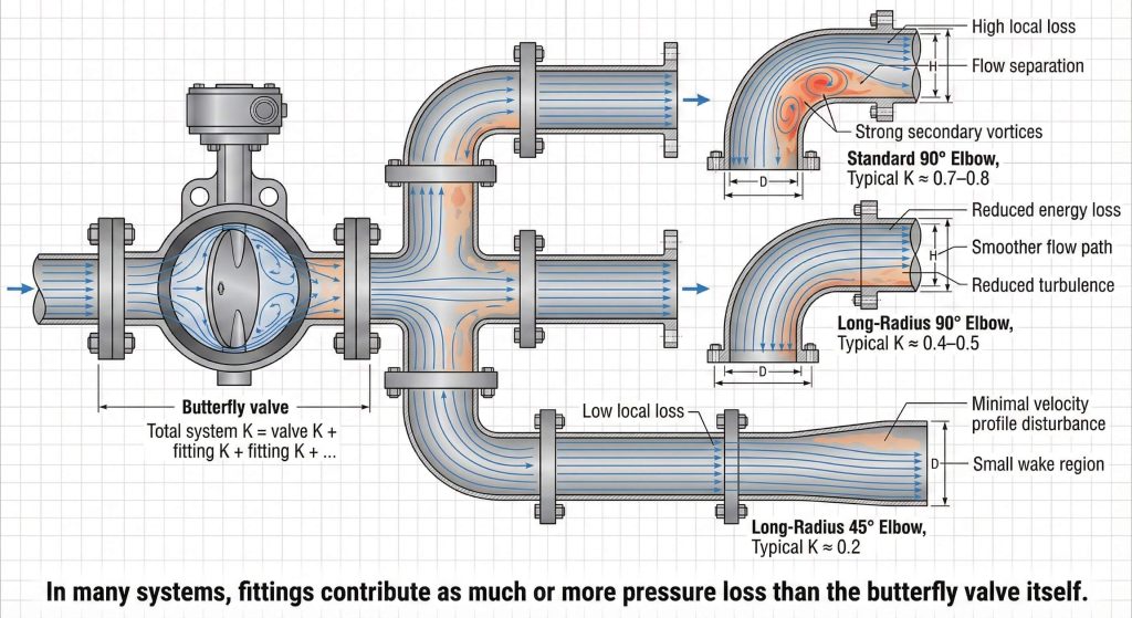
Every bare shaft butterfly valve depends on adjacent elbows and tees to maintain the overall hydraulic efficiency of the piping run. A typical installation includes various fittings that contribute to the cumulative butterfly valve k factor of the line. A standard 90-degree elbow has nearly twice the resistance of a long-radius version. Summing these values meticulously helps you determine the total friction loss before specifying the final pump head.
Elbows and bends resistance
But here’s the kicker… Using a 45-degree elbow instead of a 90-degree bend can reduce localized friction by more than half. This strategic selection is vital for systems where pressure recovery is a primary operational goal.
| Fitting Type | Radius | K Factor |
|---|---|---|
| 90° Elbow | Standard | 0.75 |
| 90° Elbow | Long Radius | 0.45 |
| 45° Elbow | Long Radius | 0.20 |
Using long-radius fittings alongside high-efficiency valves is the best strategy for minimizing the total dynamic head of your pumps.
Key Takeaway: Standard fittings often account for more pressure drop than pipes, requiring careful selection of bend radii.
8. Does roughness affect butterfly valve k factor?
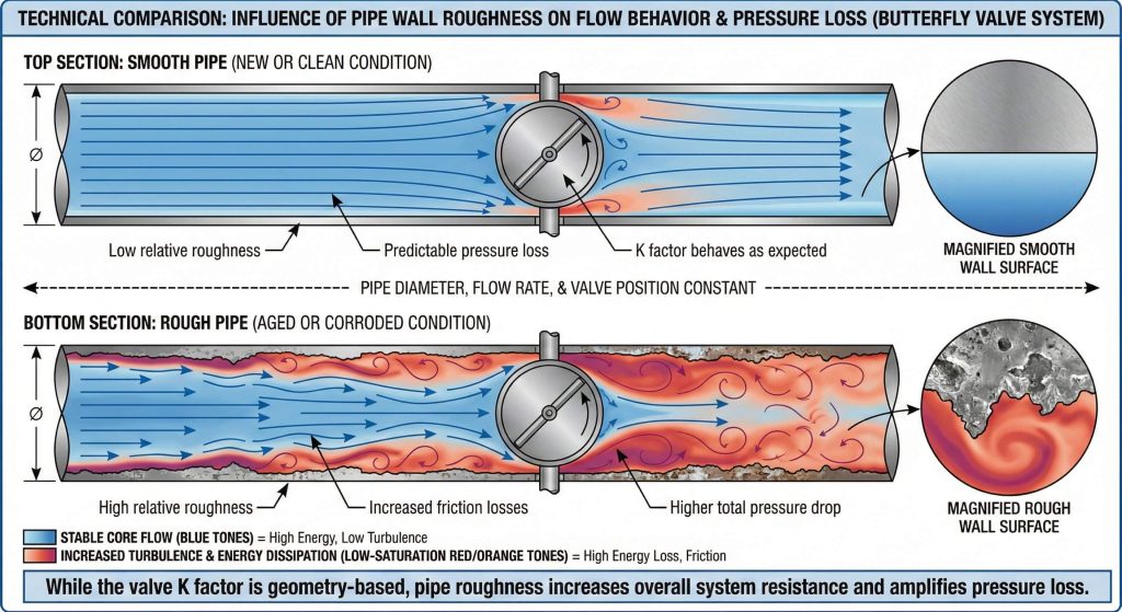
While a bare shaft butterfly valve has a shape-dependent coefficient, the overall system friction relates directly to pipe material roughness. Relative roughness of the internal walls becomes a critical variable as your piping systems age or handle corrosive media. The K factor assumes attachment toward a pipe with standard friction characteristics, so rusted iron changes the calculation. Older pipes with significant scale buildup can double the expected pressure drop of any fitting or valve.
Interaction with friction factors
What’s the real story? The K factor essentially functions as an equivalent length of straight pipe within your hydraulic model. Increased surface roughness effectively raises the localized resistance value for every single component in the network.
| Pipe Material | Condition | Roughness (mm) |
|---|---|---|
| PVC / Plastic | Smooth | 0.0015 |
| Stainless Steel | New | 0.0150 |
| Galvanized Iron | Used | 0.1500 |
Accounting for material degradation ensures your pumping systems remain functional throughout the entire lifecycle of the facility.
Key Takeaway: Surface roughness influences the boundary layer and can lead to significant energy losses in aging piping systems.
9. How to sum every butterfly valve k factor?
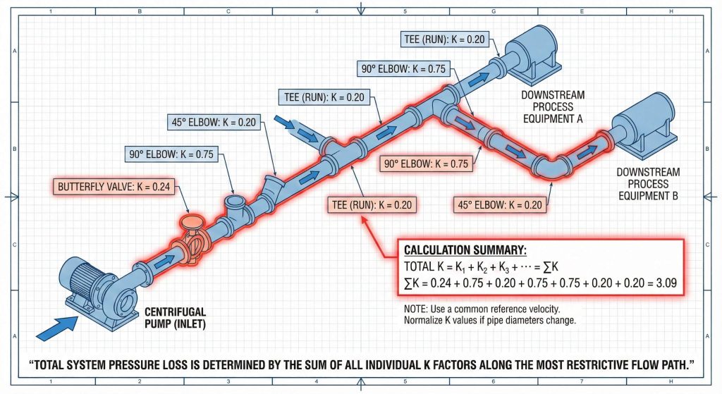
Specifying components for massive B2B projects requires a systematic approach toward calculating the total butterfly valve k factor of a line. Engineers use the “Sum of K” method to aggregate losses from every bare shaft butterfly valve, elbow, and tee. In a large facility, the cumulative coefficient can reach into the hundreds, requiring massive pump horsepower to overcome. Identifying the most restricted flow path ensures the system meets demand during peak operations.
The Sum of K methodology
Ready for the good part? You can normalize these coefficients to a single reference velocity using expansion formulas if diameters vary. This allows you to create a single resistance profile for complex manifolds with various sizes.
| Facility Area | Fitting Count | Total K (Est) |
|---|---|---|
| Pump Discharge | 12 | 15.5 |
| Main Header | 5 | 3.2 |
| Process Branch | 25 | 42.0 |
This rigorous analytical approach prevents under-performing fluid systems and reduces unexpected operational costs during commissioning.
Key Takeaway: Systematic aggregation of K factors is the only way to guarantee the hydraulic integrity of complex industrial layouts.
10. How does butterfly valve k factor relate to Cv?
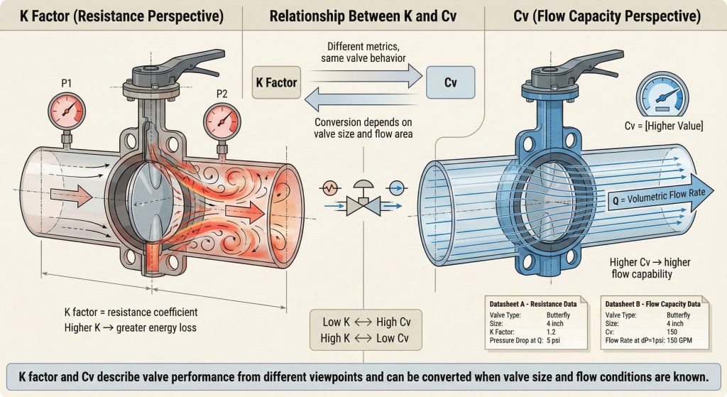
Documentation for a bare shaft butterfly valve usually mentions both the dimensionless K factor and the flow capacity coefficient Cv. While the K factor measures resistance, Cv quantifies the flow rate of water at a specific pressure drop. You can easily convert between these two using standard algebraic formulas during the procurement phase. This allows technical teams to compare various manufacturers regardless of the specific metric provided in the datasheet.
Understanding flow coefficients
This is where it gets interesting… The conversion factor depends heavily upon the internal diameter of the valve body you are using. Knowing how to switch between these metrics is a vital skill for any piping engineer or technical buyer.
| Metric Type | Definition | High Value Indication |
|---|---|---|
| K Factor | Resistance Coeff | More Loss |
| Cv / Kv | Flow Coeff | More Capacity |
| Equiv. Length | Pipe Proxy | More Friction |
Both metrics provide a window into the efficiency of your valves and the overall health of your fluid transport network.
Key Takeaway: Proficiency in converting K factors to Cv is essential for comparing hardware and sizing systems accurately.
Conclusion
Mastering the pressure drop coefficient K distinguishes sophisticated engineers who prioritize both performance and energy conservation. By accurately applying these coefficients toward every bare shaft butterfly valve and fitting, you secure a reliable and cost-effective fluid network. We encourage auditing your existing installations and utilizing high-performance components to minimize friction across your facility. If you require specialized assistance with valve selection or hydraulic calculations for your next B2B project, please contact us to speak with our technical engineering team.
FAQ
Q1: Can I use the turbulent K factor for laminar flow applications?
No, you must utilize specific laminar coefficients because energy loss physics changes significantly at low Reynolds numbers. Friction becomes dominated by fluid viscosity rather than geometric turbulence within laminar regimes. Applying turbulent values toward laminar systems results in massive calculation errors during pump selection.
Q2: What’s the best way to handle K factors if I have different pipe sizes?
You must normalize the coefficients to a single reference velocity using standard expansion and contraction formulas. Resistance increases by the fourth power of the diameter ratio, making size transitions critical to your calculation accuracy. Failing to normalize these values will lead to an incorrect total dynamic head estimation.
Q3: How do I find the K factor for a specific bare shaft butterfly valve?
Always consult the technical data sheet or flow characteristic curves provided by the manufacturer for that specific model. If the documentation only lists Cv or Kv values, use conversion formulas based upon the internal diameter of the valve. Generic tables are only suitable for preliminary design and should be replaced by verified data.
Q4: Is there a maximum K factor where a valve is considered inefficient?
While there is no single limit, any open valve with a K factor exceeding 1.0 is generally considered high-resistance for bulk transport. Globe valves often exceed 9.0, which is why they are rarely used for main headers where energy efficiency is a priority. You should aim for coefficients below 0.5 for main isolation valves.
Q5: Should I account for valve aging when selecting a K factor?
Yes, you should include a safety margin of ten to fifteen percent to account for surface degradation and potential scale buildup. This ensures that your pump remains capable of meeting demand even as the internal surface roughness of the system increases over time. Planning for the end-of-life condition prevents premature system failure.