
In the complex ecosystem of industrial fluid control, the butterfly valve represents a critical intersection of efficiency, cost, and operational reliability. You might see it as a simple “commodity” component—standard hardware found in every plant from water treatment to power generation.
However, this ubiquity leads to a dangerous complacency.
The assumption that “a butterfly valve is a butterfly valve” is the leading cause of premature seat failure, system leakage, and unplanned downtime. If you treat this sophisticated piece of engineering as a generic part, you are risking the integrity of your entire operation. Whether you are handling potable water, superheated steam, or aggressive slurries, the stakes are high.
Selecting the correct valve requires more than checking a size box. It demands a multi-dimensional analysis of mechanical architecture, material science, fluid dynamics, and lifecycle economics.
This guide is your strategic resource. We will move beyond basic definitions to explore the engineering implications of valve selection, ensuring every decision you make maximizes system integrity and operational longevity.
Here is how to navigate the selection process.
1. Architectural Analysis: Matching Design to Performance
The first tier of selection involves understanding the mechanical geometry of the valve. The core concept here is “offset”—the positioning of the stem relative to the disc and the seating surface.
Why does this matter?
This geometry dictates the friction profile, sealing capability, and pressure tolerance of the unit. Choosing the wrong offset is often why valves seize or leak prematurely.
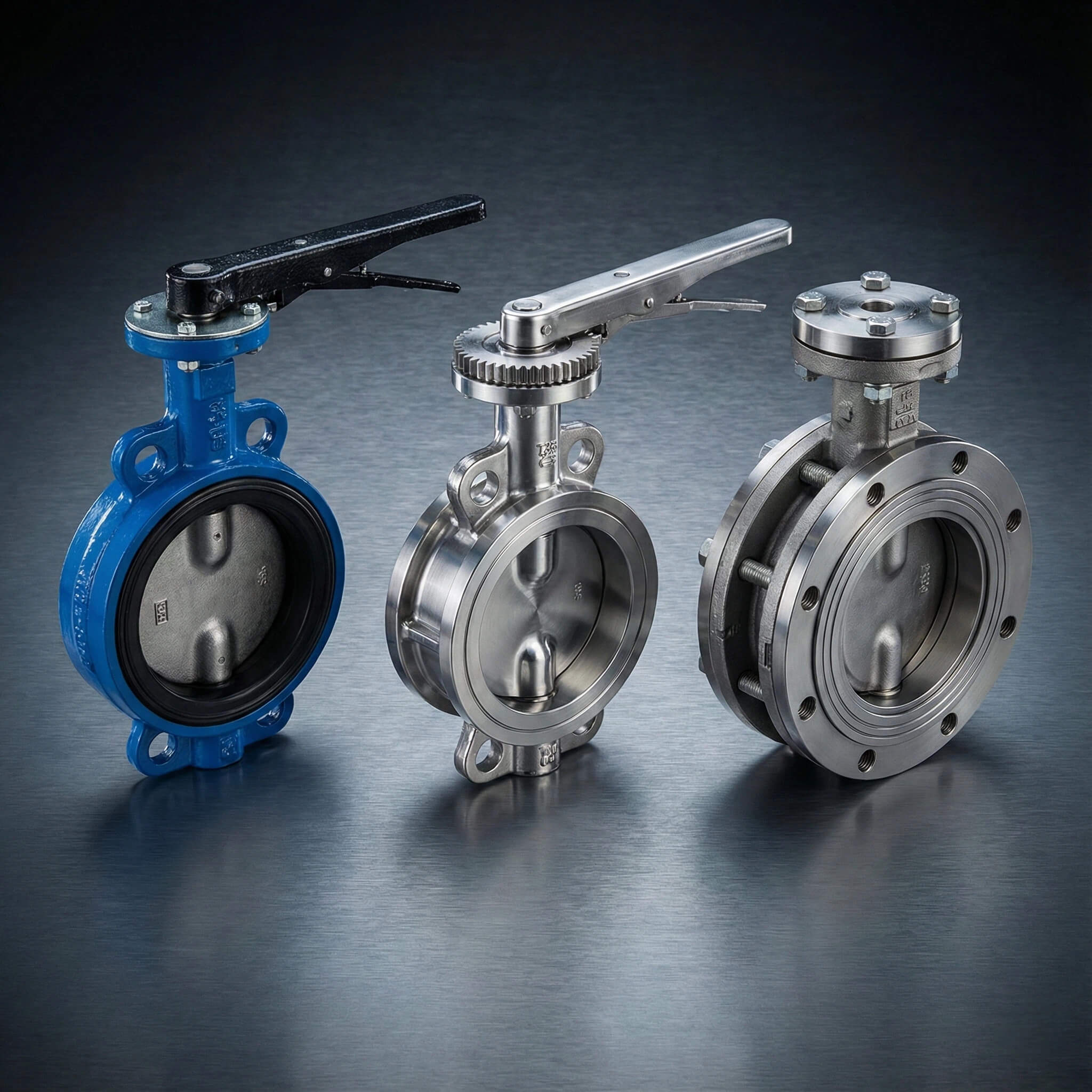
Concentric (Zero Offset): The Utility Standard
The concentric butterfly valve is likely what you picture when you think of this technology. It is the most prevalent design in general utility applications. Structurally, the stem is centered in the middle of the disc, and the disc is centered in the bore.
- The Mechanism: The disc rotates on a central axis. To achieve a seal, the disc must physically deform the soft seat (interference fit) at the 0° and 180° positions.
- The Implication: There is constant friction between the disc and the seat throughout the first and last few degrees of travel.
- Best Applications: Low-pressure water distribution, HVAC cooling towers, and chemically inert environments where bubble-tight shutoff is required at a low cost.
- Limitations: The friction limits cycle life. High pressures can deform the seat, causing leakage. It is generally not suitable for abrasive media which can embed in the soft seat.
Double Offset (High-Performance): The Industrial Workhorse
When you need to handle higher pressures and cycle rates, the concentric design falls short. Enter the double offset valve.
Engineers achieve this by shifting the geometry twice:
- Offset 1: The shaft is positioned behind the centerline of the sealing surface.
- Offset 2: The shaft is positioned slightly to one side of the pipe centerline.
- The Mechanism: These offsets create a distinct “camming” action. As the valve opens, the disc lifts off the seat almost immediately. Friction is eliminated after only a few degrees of rotation.
- The Implication: Reduced wear on the seat allows for significantly higher cycle life. The design can utilize stiffer seat materials (like reinforced PTFE) which handle higher pressures and temperatures.
- Best Applications: Chemical processing, power generation, and applications requiring modulation (throttling) capability.
Triple Offset (TOV): The Ultimate Isolation
For the most extreme conditions, you need to eliminate friction entirely.
- The Third Offset: The sealing cone axis is inclined relative to the shaft axis. This creates a conical, elliptical sealing profile.
- The Mechanism: The disc contacts the seat only at the final moment of closure. There is zero rubbing or dragging during the stroke.
- The Implication: This allows for the use of solid metal seats rather than elastomers. It provides a bubble-tight, metal-to-metal seal that is fire-safe and impervious to seal degradation.
- Best Applications: Superheated steam, lethal gases, extreme temperatures (-196°C to +500°C), and refinery isolation where leakage is not an option.
Expert Analysis: Architecture Comparison
| Feature | Concentric (Resilient Seated) | Double Offset (High Performance) | Triple Offset (TOV) |
|---|---|---|---|
| Pressure Rating | Low (up to 150-250 PSI) | Medium/High (up to 740 PSI) | Extreme (up to 1500+ PSI) |
| Seat Material | Elastomer (Rubber/EPDM) | Polymer (PTFE/RTFE) | Metal / Laminated Metal |
| Wear Profile | High friction (rubbing) | Low friction (cam action) | Zero friction (torque seating) |
| Primary Failure | Seat degradation/deformation | Seat wear over high cycles | Actuator failure (rare) |
| Cost Index | $ | $$$ | $$$$$ |
2. Material Science: The Chemistry of Compatibility
Once you have selected the mechanical architecture, the focus must shift to material compatibility. A valve is an assembly of components—Body, Disc, Seat, and Stem—and each must chemically and thermally withstand your media.
Body Materials: Structural Integrity
The body contains the system pressure. Failure here is catastrophic.
- Cast Iron (Gray/Ductile): The standard for water systems. Ductile iron is preferred for its higher tensile strength and impact resistance compared to brittle gray iron.
- Carbon Steel (WCB): Essential for high-pressure and high-temperature industrial loops where thermal shock is a risk.
- Stainless Steel (304/316): The baseline for corrosive external environments (offshore) or sanitary requirements (food/pharma).
- Aluminum Bronze: Specifically engineered for seawater applications to resist chloride pitting and biofouling.
Disc Materials: The Dynamic Element
The disc sits in the flow stream continuously. While coated ductile iron is cost-effective, it is prone to corrosion if the coating (often Nylon or Epoxy) is chipped by debris.
For more robust applications, Stainless Steel (CF8M) is the standard, resisting erosion and cavitation better than iron. For aggressive acids like sulfuric or hydrochloric acid, you must look to exotic alloys like Hastelloy or Titanium, as stainless steel would dissolve.
Seat Materials: The Critical Seal
The seat is the most vulnerable component. Selecting the wrong elastomer is the number one cause of valve failure.
Expert Insight: Never assume “universal” compatibility. A common error is using EPDM seats in a system that contains trace amounts of oil from pumps or compressors. Even 1% oil content can cause EPDM to swell, locking the valve in position and burning out the actuator.
Refer to the table below to ensure you match the chemistry correctly:
| Material | Common Trade Name | Temperature Range | Best Application | Fatal Weakness |
|---|---|---|---|---|
| EPDM | Ethylene Propylene | -20°F to 250°F | Water, Steam, Glycol, Phosphates | Oil & Hydrocarbons. Instant swelling and failure. |
| NBR | Buna-N / Nitrile | -10°F to 180°F | Petroleum oils, Fuels, Lubricants | Ozone & Sunlight. Cracks quickly if exposed outdoors. |
| FKM | Viton® | -20°F to 400°F | Strong acids, Hydrocarbons, High heat | Steam. Can degrade in continuous steam service. |
| PTFE | Teflon® | -50°F to 400°F | Almost all chemicals, Solvents | Abrasion. Soft material erodes easily in slurries. |
3. Operational Dynamics: Pressure, Temperature, and Flow
Selecting a valve requires calculating the physics of the system. It is not enough to match the pipe size; you must match the flow characteristics.
Pressure and Temperature (P/T) Ratings
Pressure and temperature are inversely related. As temperature rises, the pressure-holding capability of materials decreases. You need to watch for two phenomena:
- Cold Flow (Creep): In PTFE-seated valves, high pressure combined with high temperature can cause the seat to deform or “flow” downstream, compromising the seal.
- Thermal Shock: Rapid temperature changes can cause the disc to expand faster than the body, potentially seizing the valve. For applications with temperature swings >100°F, ensure adequate clearance or use high-performance designs.
Flow Characteristics and Sizing
A common mistake is “line-sizing” (e.g., putting a 6-inch valve in a 6-inch pipe) without checking flow dynamics.
You must evaluate the Cv Factor (Flow Coefficient), which represents the volume of water in GPM that flows through a valve with a 1 PSI pressure drop. Furthermore, understand the control range:
- Below 30% Open: The flow is too restricted, leading to high velocity, noise, and “wire drawing” (erosion of the seat).
- Above 70% Open: The valve acts almost as a full pipe; small movements have little effect on flow rate.
- Cavitation Risk: In high-pressure-drop situations, fluid pressure can drop below its vapor pressure, forming bubbles that collapse destructively. If cavitation is predicted, a butterfly valve may be the wrong choice entirely; a globe or specialized control valve might be required.
4. Installation Styles: Wafer vs. Lug
The method of connecting the valve to the piping system dictates your maintenance procedures and safety protocols for the life of the plant.
Wafer Style
This design features a body that typically lacks threaded holes. It is “sandwiched” between two flanges using long bolts that span the entire valve length.
- Pros: Lightweight, lower cost, easy to install in new construction.
- Cons: Cannot be used for dead-end service. If you unbolt the downstream pipe, the entire valve falls out, emptying the upstream system. This is a critical safety limitation.
Lug Style
The body features threaded inserts (lugs) matching the bolt pattern of the flange. Bolts are installed from both sides independently.
- Pros: Allows for downstream piping removal while maintaining upstream pressure (Dead-End Service). This is essential for maintenance isolation.
- Cons: Heavier, slightly more expensive, and thread compatibility must be precise.
Strategic Consideration: For any critical isolation point where maintenance might occur downstream, Lug style is mandatory. Saving $50 on a Wafer valve is negligible compared to the cost of draining an entire system to replace a downstream gasket.
5. Industry-Specific Application Strategies
Different sectors have unique regulatory and physical demands that override standard selection criteria. Here is how to adapt your strategy based on your industry.
Water and Wastewater Treatment
- The Challenge: Corrosion from chlorine, abrasive grit, and large scale.
- The Strategy: Use large diameter (24″+) Concentric valves.
- Body: Ductile Iron (Epoxy coated).
- Disc: SS316 or Aluminum Bronze (to resist bio-fouling).
- Seat: EPDM (Chloramine resistant).
- Note: In wastewater, “ragging” (debris wrapping around the stem) is a risk, so smooth disc profiles are preferred.
Oil and Gas / Petrochemical
- The Challenge: Flammability, fugitive emissions, and high pressure.
- The Strategy: Double or Triple Offset Valves are non-negotiable.
- Standards: Must meet API 607 (Fire Safe) and API 609 standards.
- Seal: Metal or Graphite-laminated seats to survive fire incidents.
- Stem: Anti-blowout stem design is a mandatory safety feature.
Food and Beverage / Pharma
- The Challenge: Bacterial growth, cleaning protocols (CIP), FDA compliance.
- The Strategy: Sanitary Butterfly Valves.
- Material: Polished SS316L (Ra < 0.8µm) to prevent biofilm adhesion.
- Design: Split-body designs for easy disassembly and cleaning.
- Seat: FDA-approved Silicone or EPDM that can withstand steam sterilization (250°F+).
HVAC and District Cooling
- The Challenge: Balancing flow, condensation, and actuator cycling.
- The Strategy: Wafer-style Concentric valves.
- Body: Aluminum bodies (for weight savings) or Cast Iron.
- Seat: EPDM is standard.
- Actuation: Often paired with electric actuators for building management system (BMS) integration.
6. The Economics of Valve Selection: TCO Analysis
The purchase price of a valve often represents less than 10% of its lifecycle cost. Engineers must evaluate the Total Cost of Ownership (TCO).
The “Low Bid” Trap
Imagine purchasing a generic cast-iron valve for a chemical slurry line to save $200 upfront.
- Failure Rate: The abrasive slurry destroys the soft seat in 3 months.
- Replacement Cost: New valve ($200) + Maintenance Labor ($500) + System Downtime ($5,000/hour).
- Result: The “cheap” valve costs the company thousands in the first year.
The High-Performance Dividend
Conversely, investing in a Double Offset valve with a hardened seat might cost $800 upfront.
- Lifespan: Lasts 3 years due to camming action reducing wear.
- Maintenance: Zero interventions required.
- Result: Massive ROI through uninterrupted production.
Cost vs. Durability Hierarchy:
- Commodity (Rubber Lined): Low Cost / Low Durability in harsh service.
- High Performance (PTFE Seated): Medium Cost / High Durability in chemical service.
- Severe Service (Metal Seated): High Cost / Extreme Durability in thermal/pressure service.
7. Common Pitfalls and How to Avoid Them
Even experienced engineers can fall victim to specific oversight errors during the specification process.
1. Ignoring Actuator Sizing (The “Stuck Valve” Syndrome)
Valves develop “breakout torque” after sitting static for long periods. This torque is significantly higher than the running torque.
- The Mistake: Sizing the actuator based on running torque.
- The Consequence: The valve sticks shut, burning out the electric motor or stalling the pneumatic piston.
- The Fix: Always apply a safety factor (typically 25-30%) to the manufacturer’s breakout torque rating.
2. The Check Valve Interference
- The Mistake: Bolting a wafer butterfly valve directly to a wafer check valve (dual plate).
- The Consequence: The butterfly disc opens into the pipe space. If the check valve plates are close, the disc hits them, preventing full opening or damaging the disc edge.
- The Fix: Install a spacer spool between the butterfly valve and adjacent components.
3. Dry Operation
- The Mistake: Operating a rubber-seated valve “dry” during testing.
- The Consequence: Rubber seats rely on the fluid for lubrication. Dry cycling creates high friction, tearing the seat before the system is even live.
- The Fix: Lubricate the seat or ensure the line is wet before major cycling tests.
4. Vacuum Service Oversight
- The Mistake: Using a standard liner for vacuum service.
- The Consequence: Vacuum can pull a bonded liner away from the body, collapsing the seat into the flow path and jamming the valve.
- The Fix: Specify fully bonded (vulcanized) liners specifically rated for vacuum service.
Conclusion
Selecting the right butterfly valve is an exercise in risk management and system optimization. It requires moving beyond the catalog part number to understand the interactions between the valve’s geometry, the material’s chemistry, and the system’s physics.
The Final Checklist for Selection:
- Define the Mission: Is this for isolation (On/Off) or Control (Throttling)?
- Analyze the Media: What is the chemical composition, temperature, and viscosity? (Check compatibility charts).
- Select the Geometry: Concentric for water; Eccentric for industry; Triple Offset for extreme/steam.
- Verify the Ratings: Does the P/T rating exceed the system’s maximum spike (not just average)?
- Choose the Installation: Lug style for maintenance flexibility; Wafer for cost savings.
- Calculate the Flow: Is the valve sized for a 30-70% opening angle at operational flow?
By rigorously applying these criteria, you ensure that your valve selection acts not as a bottleneck, but as a reliable guardian of process integrity.
Ready to optimize your system? Don’t leave your infrastructure to chance. Consult with a valve engineering specialist to audit your specifications today.
Frequently Asked Questions
- Can I use a concentric butterfly valve for steam applications?
Generally, no. Standard concentric valves use elastomer seats like EPDM which have lower temperature limits. While EPDM can handle low-pressure steam, continuous exposure often degrades the seat. For steam, High-Performance (Double Offset) or Triple Offset valves with metal or reinforced PTFE seats are the safe, durable choice. - What is the main difference between Wafer and Lug style valves?
The main difference is the bolt connection. Wafer valves are sandwiched between flanges using long bolts, making them impossible to use for dead-end service (removing downstream piping). Lug valves have threaded inserts, allowing bolts to be removed from one side while maintaining pressure on the other, which is critical for maintenance. - Why did my EPDM seat fail immediately in an oil line?
EPDM is chemically incompatible with oils and hydrocarbons. Even a small amount of oil will cause EPDM to swell rapidly, increasing torque and causing the rubber to disintegrate. For oil applications, you must use NBR (Buna-N) or High-Performance valves with PTFE seats. - How much safety factor should I add when sizing an actuator?
You should always add a safety factor of at least 25-30% to the valve’s rated breakout torque. Valves that sit idle for long periods develop higher friction (“breakout torque”) than their operational running torque. Under-sizing the actuator will result in a stuck valve that cannot open when needed.