A butterfly valve symbol is a standardized graphical representation used in engineering drawings, such as P&IDs and isometric diagrams, to indicate the presence and orientation of a quarter-turn valve with a rotating disc. Imagine you are reviewing a massive piping project with hundreds of intersection points and critical flow paths. You cannot afford to misinterpret a single component, as a wrong valve choice leads to catastrophic pressure drops or system failure. To eliminate these costly errors, you must master the butterfly valve schematic symbol to ensure every fluid control point in your facility operates with precision.
What is a butterfly valve schematic symbol?
A butterfly valve schematic symbol is a specific icon comprising two triangles pointing toward a central line that represents the valve’s rotating disc. You will notice that unlike globe or gate valves, which use solid or empty triangles, this symbol focuses on the shaft mechanism.
Identifying the Core Icon
Does the symbol look like a bowtie with a line through it? This visual shorthand is recognized globally across all major industrial engineering standards. Here is the kicker:
- The triangles represent the valve body.
- The center line indicates the disc and stem.
- The overall shape reflects the space-saving nature of the hardware.
Why Design Detail Matters
You need to recognize these icons to prevent installation errors on the shop floor. Standardized icons ensure that a design created in one country is perfectly understood by a contractor in another. But wait, there is more:
- It helps in rapid identification during emergency shutdowns.
- The symbol dictates the clearance required for the lever or actuator.
- It ensures the bill of materials matches the schematic exactly.
Key Takeaway
The butterfly valve schematic symbol is the universal language for identifying quarter-turn disc valves in industrial blueprints.
| Element | Graphic | Functional Meaning |
|---|---|---|
| Body | Two Triangles | Pressure-containing housing |
| Disc | Vertical/Slanted Line | The rotating flow-control element |
| Shaft | Central Axis | The component connecting disc to handle |
Understanding these basic components is the first step toward error-free P&ID interpretation and system design.
Where is the butterfly valve schematic symbol used?
The butterfly valve schematic symbol is primarily used in Piping and Instrumentation Diagrams (P&ID) and isometric drawings to map out fluid control logic. You will encounter these symbols whenever you are analyzing water treatment, HVAC, or chemical processing layouts.
Mapping P&ID Layouts
In a P&ID, the symbol tells you exactly where flow can be throttled or isolated. This is crucial for maintaining the safety and efficiency of your high-volume piping systems.
- It indicates the functional location within a process loop.
- The symbol shows relationship to sensors and pumps.
- It aids in the automated logic design for control systems.
Application in Isometric Drawings
When you transition to 3D construction drawings, the symbol helps you visualize physical space. It ensures that the valve handle has enough room to rotate a full 90 degrees without hitting other pipes.
- Shows physical orientation of the stem.
- Indicates the face-to-face dimension requirements.
- Helps pipefitters align the valve correctly with the flow.
Key Takeaway
You will find the butterfly valve schematic symbol in every critical document used for the design, construction, and maintenance of industrial fluid systems.
| Document | Primary Focus | Symbol Detail Level |
|---|---|---|
| P&ID | Functional Logic | Standardized / Abstract |
| Isometric | Spatial Placement | Orientation-Specific |
| CAD Model | Physical Fit | High-Resolution / Dimensional |
Reliable documentation ensures that every engineer on your team is working from the same functional blueprint.
How to read a butterfly valve schematic symbol?
To read a butterfly valve schematic symbol, you must look at the orientation of the central line relative to the triangles and the piping path. A line drawn perpendicular to the pipe typically signifies a closed state, while a parallel line indicates an open valve.
Deciphering the Disc Position
How do you know if the valve is currently blocking flow? You simply check the angle of the “butterfly” line in the center of the bowtie icon.
- Horizontal lines usually mean the valve is open.
- Vertical lines crossing the triangles mean it is closed.
- Diagonal lines may represent a specific throttling position.
Distinguishing End Connections
You must also look for small marks at the tips of the triangles to understand how the valve attaches to the pipe. Here is the kicker:
- Double vertical bars indicate a flanged connection.
- Parallel lines close to the body signify a wafer style.
- Small dots or circles might represent a lug-style interface.
Key Takeaway
Reading a butterfly valve schematic symbol involves identifying the disc angle and the end-connection markings to understand operational status and mounting needs.
| Symbol Feature | Visual Indicator | Operational Meaning |
|---|---|---|
| Center Line Angle | 90° to Pipe | Flow is isolated (Closed) |
| Center Line Angle | Parallel to Pipe | Flow is passing (Open) |
| Tip Markings | Vertical Bars | Bolted flange connection |
Accurate reading prevents you from accidentally opening or closing critical lines during sensitive process phases.
Why does the butterfly valve schematic symbol vary?
The butterfly valve schematic symbol varies because different regional and industrial standards, such as ISO, ANSI, and DIN, have unique drawing conventions. You might see a solid line in one project and a hollow triangle in another depending on the lead engineer’s preference.
Regional Standard Influence
Are you working on a project for a European or North American client? The standards they follow—ISO 14617 versus ANSI/ISA S5.1—will dictate the visual style of your schematic.
- ISO tends to favor more geometric, abstract shapes.
- ANSI often includes more descriptive, functional details.
- JIS standards may introduce specific symbols for marine use.
Manufacturer Customizations
Some manufacturers provide detailed CAD blocks that include proprietary symbols for high-performance valves. You might find symbols that specifically call out triple-offset or PTFE-lined features for specialized applications.
- Modified symbols indicate unique sealing capabilities.
- Custom icons help distinguish between low and high-pressure units.
- Specific markings can identify fire-safe designs.
Key Takeaway
Variations in the butterfly valve schematic symbol are driven by the specific engineering standards and the technical complexity of the valve’s application.
| Standard | Typical Style | Primary Region |
|---|---|---|
| ISO 14617 | Clean, geometric bowtie | International / Europe |
| ANSI/ISA S5.1 | Detailed, functional icons | North America |
| DIN | Strict adherence to line weights | Germany / EU |
Navigating these variations ensures your project remains compliant with local regulations and international best practices.
What standards define a butterfly valve schematic symbol?
The butterfly valve schematic symbol is primarily defined by the ISO 14617 and ANSI/ISA S5.1 international standards. These documents provide the rigorous guidelines that keep industrial drawings consistent across global supply chains.

Universal ISO Guidelines
ISO 14617 is the gold standard for many international EPC contractors. It focuses on creating a “universal language” that you can read regardless of your native tongue.
- Ensures consistent icon sizes across different drawings.
- Standardizes the thickness of the lines used.
- Defines how to show different types of actuators.
ANSI and North American Context
In North American projects, the ISA S5.1 standard is the most common reference you will find. It emphasizes the function of the valve within the control loop.
- Includes specific letters like “HV” for hand valves.
- Provides clear symbols for fail-safe positions.
- Integrates valve icons with electrical and pneumatic signals.
Key Takeaway
Following recognized standards for the butterfly valve schematic symbol ensures that your technical drawings are professional, traceable, and legally compliant.
| Standard | Full Title | Best Used For |
|---|---|---|
| ISO 14617 | Graphical symbols for diagrams | Global / Multi-national projects |
| ANSI/ISA S5.1 | Instrumentation Symbols | North American / Process Control |
| API 609 | Butterfly Valve Design | Technical specification cross-ref |
Adherence to these standards is what separates amateur sketches from reliable, high-integrity engineering documentation.
How to draw a wafer butterfly valve schematic symbol?
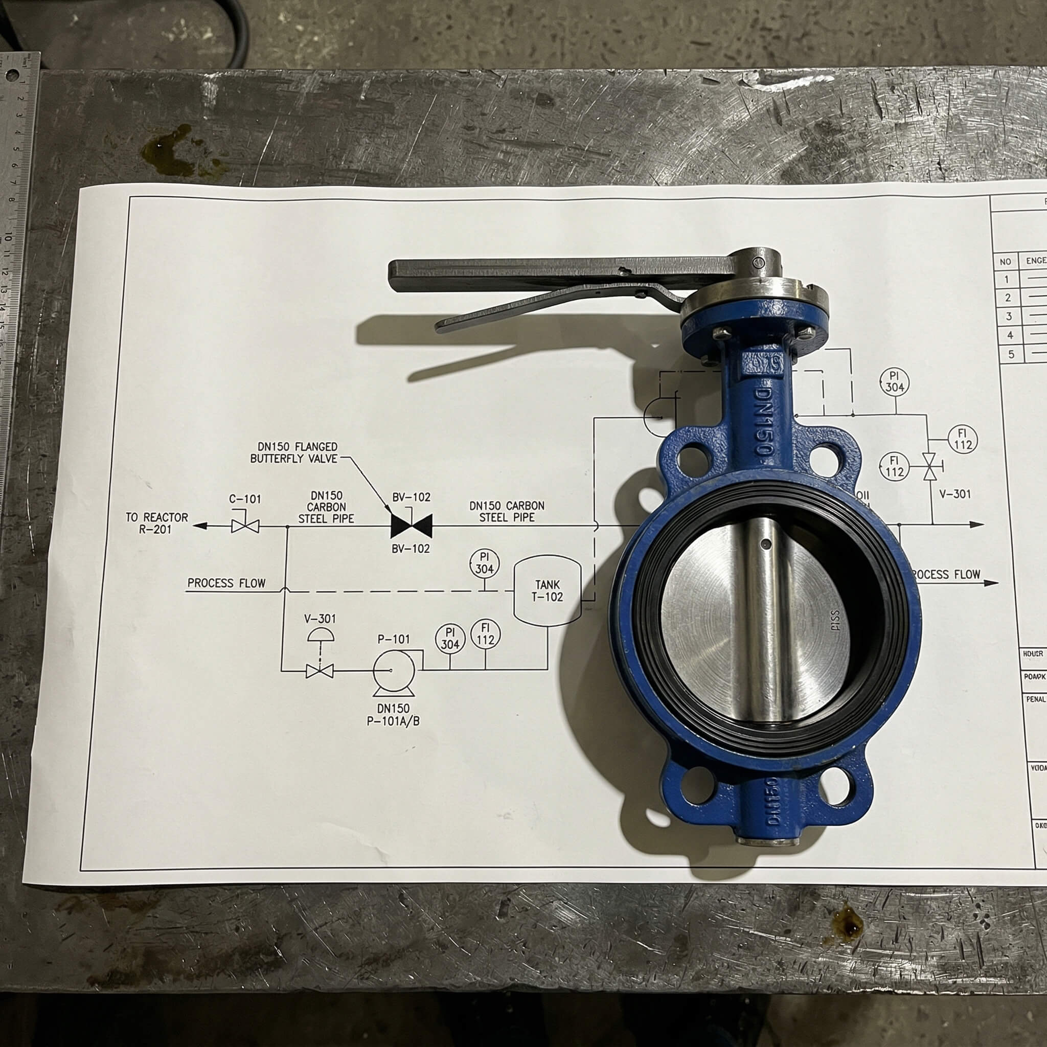
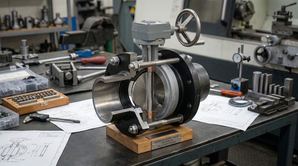
To draw a wafer butterfly valve schematic symbol, you place the standard bowtie icon between two parallel lines that represent the pipe flanges. This “sandwich” look communicates that the valve body does not have its own flanges but is held in place by the surrounding pipes.
Representing the Sandwich Design
Because wafer valves are designed for compact spaces, you must draw the symbol tightly. Here is the kicker:
- Draw two pipe lines ending abruptly.
- Place the butterfly icon in the gap.
- Ensure no extra bolts or bars are shown outside the body.
Showing Face-to-Face Dimensions
While the symbol is abstract, you should try to represent the narrow profile of the wafer design. This helps engineers who are checking the technical specifications against the drawing.
- Keep the triangles narrow to reflect a thin body.
- Focus on the central disc as the primary feature.
- Label the size clearly (e.g., DN100) next to the icon.
Key Takeaway
Drawing a wafer symbol requires focusing on the “sandwiched” placement between pipe flanges without additional bolting marks.
| Component | Drawing Step | Visual Effect |
|---|---|---|
| Pipe End | Two parallel vertical lines | Represents the existing flange |
| Valve Body | Centered bowtie | Shows the quarter-turn mechanism |
| Disc Line | Vertical/Slanted mark | Indicates the internal disc position |
Mastering this drawing technique prevents confusion between wafer, lug, and flanged styles during the procurement phase.
Does a flanged butterfly valve schematic symbol differ?
The butterfly valve schematic symbol for a flanged type differs by adding vertical bars at the outer edges of the triangles. These bars signify that the valve body has integral flanges which are bolted directly to the piping system.
Visual Cues for Bolted Ends
You can instantly tell a flanged valve apart because of these additional lines. They change the bowtie into a more robust, “capped” icon.
- The bars represent the mating surface of the flange.
- They imply a heavier-duty connection compared to wafer styles.
- These are often used for larger sizes like DN300 to DN1200.
Lug vs. Flange Comparison
But wait, there is more: don’t confuse flanged symbols with lug symbols. While flanged symbols use solid bars, lug symbols might use small circles to show threaded inserts.
- Flanged symbols are for double-bolted systems.
- Lug symbols show the valve can be used for end-of-line service.
- Proper symbols prevent “interface risks” during project handover.
Key Takeaway
Flanged symbols are identified by the vertical bars on the triangle tips, indicating a secure, independent bolting system.
| Connection | Symbol Identifier | Common Size Range |
|---|---|---|
| Flanged | Vertical bars at tips | DN200 – DN3000 |
| Lug | Small circles/dots on body | DN50 – DN600 |
| Wafer | No extra marks/Plain bowtie | DN50 – DN1200 |
Selecting the right symbol ensures that your piping team buys the correct mounting hardware for the job.
How to show an actuated butterfly valve schematic symbol?
You show an actuated butterfly valve schematic symbol by adding a secondary icon, such as a square or a semi-circle, above the stem of the valve. This modifier tells you if the valve is operated by a manual lever, a gearbox, or a pneumatic motor.
Manual vs. Gear Operation
Most small valves are hand-operated, but as you scale up, you need gears. Here is the kicker:
- A simple “T” or “L” indicates a manual lever.
- A small circle or square with a diagonal line represents a worm gear.
- These manual symbols are essential for non-automated process lines.
Pneumatic and Electric Actuation
For modern automated plants, you need to show remote control capabilities. This is critical for engineers who contact technical support for system integration.
- A square with an “E” identifies an electric actuator.
- A semi-circle or “M” shape represents a pneumatic diaphragm.
- Fail-safe directions are shown with small arrows (FO/FC).
Key Takeaway
Actuation is represented by a standardized “cap” on top of the valve symbol that defines the driving power source.
| Actuator | Symbol Cap | Common Power Source |
|---|---|---|
| Manual Lever | Flat bar or “T” | Human force (90°) |
| Pneumatic | Semi-circle/Dome | Compressed Air |
| Electric | Square with “E” | 110V/220V AC or DC |
Including actuator details ensures your control system designers can map out the wiring and air supply lines correctly.
Who provides the best butterfly valve schematic symbol?
The best butterfly valve schematic symbol is provided by professional manufacturers who offer ISO-certified CAD and 3D modeling libraries. You should look for suppliers like RUITO who provide comprehensive technical dossiers to support your EPC and OEM projects.
Sourcing Factory-Verified Symbols
Why settle for generic icons when you can use factory-verified data? Using symbols from a trusted manufacturer reduces your “defect rate” during the design phase.
- Ensures dimensions match the physical product.
- Provides clear material traceability (MTC).
- Guarantees compliance with DNV, CE, and WRAS standards.
Utilizing Professional CAD Libraries
Many top-tier suppliers provide downloadable 2D and 3D symbols for free. This saves you time and ensures your P&IDs are ready for high-level industrial audits.
- Speeds up the drafting process for EPCs.
- Eliminates the risk of drawing a flanged valve for a wafer quote.
- Provides a professional appearance to your client presentations.
Key Takeaway
High-quality symbols come from certified manufacturers who integrate their technical documentation with international engineering standards.
| Provider | Data Quality | Support Services |
|---|---|---|
| RUITO | High (Certified) | 24-Hour Technical Response |
| Standard Libraries | Medium | No direct project support |
| Manual Sketches | Low | Prone to human error |
Partnering with an experienced manufacturer ensures that your fluid control designs are as reliable as the valves themselves.
How to verify your butterfly valve schematic symbol?
To verify your butterfly valve schematic symbol, you must cross-reference it against the manufacturer’s technical data sheet and the project’s Piping Specification. Always check that the symbol’s pressure rating and connection type match the physical valve you intend to purchase.
Cross-Checking Pressure and Temp
Does the symbol on your P&ID represent a PN16 or PN40 valve? You must ensure the text callouts next to the icon align with the system’s operating conditions.
- Check the symbol against the material list (DI vs. SS).
- Verify the temperature rating for the seat material (EPDM/PTFE).
- Ensure the pressure class matches the flange standard (ANSI/DIN).
Final Drawing Approval Steps
Before you sign off on a design, perform a “clash detection” using the valve symbol in a 3D model. This confirms that the valve will actually fit and operate in the real-world environment.
- Verify the stem orientation for maintenance access.
- Check that the handle won’t hit adjacent structures.
- Confirm that the symbol correctly shows the flow direction if needed.
Key Takeaway
Verification is a three-step process: matching the symbol to the data sheet, checking material specs, and performing a spatial fit test.
| Step | Verification Action | Goal |
|---|---|---|
| 1 | Symbol vs. Data Sheet | Correct valve type identification |
| 2 | Callout vs. Spec | Material and pressure compliance |
| 3 | Symbol vs. 3D Space | Physical clearance and operation |
By following these verification steps, you eliminate the schedule delays and interface risks that plague poorly documented industrial projects.
Conclusion
Mastering the butterfly valve symbol is the key to preventing costly design errors and ensuring the long-term reliability of your fluid control systems. We have explored how these standardized icons communicate critical information about disc position, end connections, and actuation methods across global industrial standards. By utilizing professional documentation and sourcing from experts, you can de-risk your procurement process and keep your projects on schedule.
Our team at RUITO is dedicated to providing the high-reliability, precision-engineered valves and technical support you need for your most demanding applications. Whether you are managing a municipal water network or a complex chemical plant, our 15 years of manufacturing excellence and international certifications stand behind every product we deliver. If you are ready to optimize your next project with traceable quality and expert engineering support, contact us today to discuss your specific requirements and receive a technical consultation.
Frequently Asked Questions
Can I use a ball valve symbol instead of a butterfly valve?
No, you should not interchange them. While both are quarter-turn, a ball valve symbol uses a circle between triangles, and the butterfly valve schematic symbol specifically uses a central line to represent the disc.
What’s the best way to show a fail-safe position?
The best way is to place an arrow next to the actuator. An arrow pointing toward the pipe means “Fail Closed,” while an arrow pointing away from the pipe means “Fail Open.”
How do I know if a symbol represents a triple-offset valve?
You usually know by looking for a specific text callout (TOV) or a slightly modified triangle shape. These high-performance valves often require more detailed symbol modifiers to distinguish them from standard concentric types.
Can I draw a lug valve symbol without circles?
No, it is not recommended. Including small circles or “lugs” on the symbol is the only clear way to distinguish it from a wafer valve, which is critical for engineers planning end-of-line maintenance.
What is the symbol for a motorized butterfly valve?
The symbol for a motorized valve is the standard bowtie with a square “E” on top. This indicates an electric motor is used rather than manual or pneumatic force.