
Engineers often face a critical dilemma when specifying piping components for fluid control. Selecting an incorrect valve connection leads directly toward catastrophic leaks, costly system downtime, and spiraling maintenance expenses. A single mismatch between pipe flanges and valve bodies disrupts entire production lines, causing headaches that no plant manager wants. Here is the deal: understanding distinct end connection types prevents these expensive errors and secures your operation’s efficiency. This guide details every major connection style, providing the specific knowledge you need for precise component selection. With years of experience delivering over 150,000 units annually, we offer the practical expertise required for reliable decision-making.
1. What Defines a Wafer Type Connection?
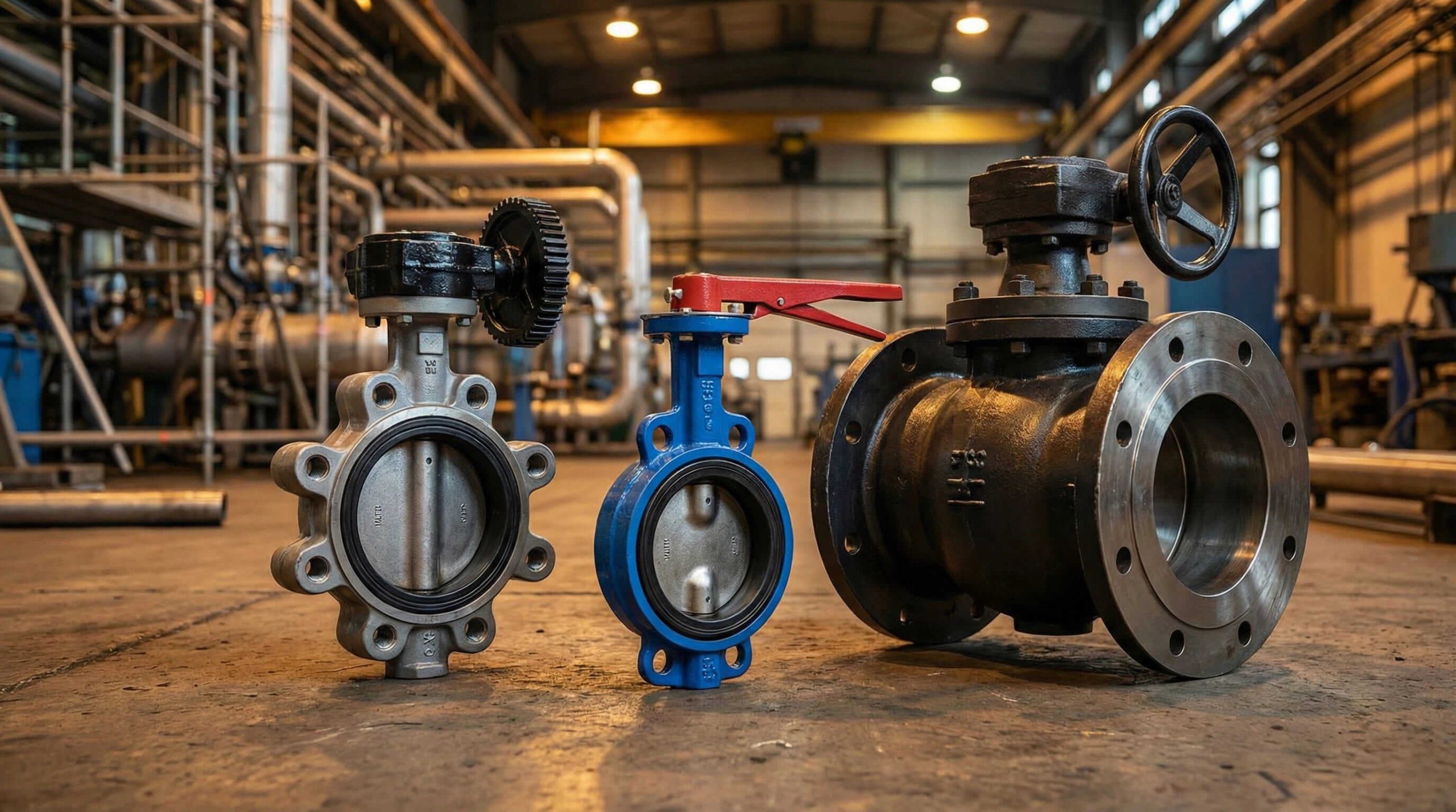
Wafer connections represent the most economical choice found in industrial applications today. These units feature a slim body design that fits snugly between two pipe flanges. Long bolts pass through the pipe flanges and surround the valve body, effectively sandwiching it in place. This “sandwich” configuration minimizes weight and material usage significantly. You might be wondering why this matters so much. Reducing weight lowers the load-bearing requirements for the piping supports, which saves money on structural costs.
Budget constraints often dictate component selection in large projects. Wafer valves utilize less metal material than their flanged counterparts, resulting in lower unit costs for buyers. Procurement managers typically see savings of 20-30% on initial capital expenditure when choosing wafer styles for general utility lines. Rugged materials like ductile iron or stainless steel guarantee durability despite the lighter frame.
Installing a Wafer Butterfly Valve requires precision but offers speed advantages. Installers center the valve using the bolt circle of the mating flanges. Some designs include centering holes to aid alignment. This connection type relies heavily on the compressive force of the flange bolts to maintain a tight seal. Proper torque application prevents gasket extrusion or leakage.
| Feature | Description | Benefit |
|---|---|---|
| Design | Sandwiched between flanges | Compact, lightweight |
| Bolting | Long through-bolts | Uses fewer bolts overall |
| Cost | Minimal material use | Lowest initial price |
| Application | General utility, HVAC | Fits tight spaces |
2. How Does a Lug Style Connection Work?
Lug valves differ fundamentally from wafer types due to metal inserts incorporated into the body. The valve body contains threaded lugs positioned around its circumference. These lugs match the bolt pattern of standard pipe flanges perfectly. Installers secure bolts through the pipe flange directly into the valve body. This independent bolting mechanism creates a secure, rigid joint that withstands vibration better than clamped connections.
Many industrial systems require end-of-line isolation for maintenance. Wafer valves fail here because removing the downstream flange releases the valve completely. But here’s the kicker: Lug valves solve this problem instantly. You can bolt a lug valve to the upstream flange and remove downstream piping for maintenance or expansion. This capability makes lug styles indispensable for future-proofing facility layouts and servicing equipment without full shutdowns.
Maintenance teams prefer Lug Butterfly Valve connections for critical infrastructure. If a pump requires servicing, technicians isolate the line using a lug valve bolted to the manifold. The secure connection maintains system pressure upstream. Always verify the pressure rating for dead-end service, as it sometimes differs from the standard rating.
3. Why Choose Double Flanged Connections?
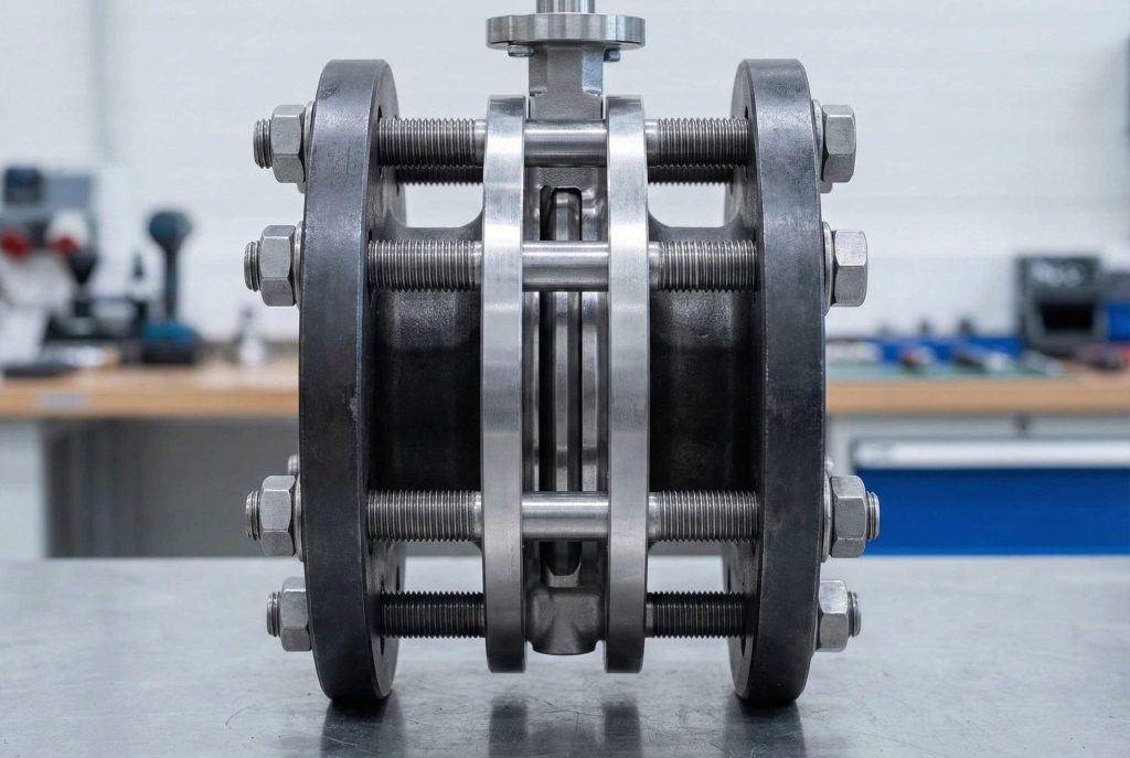
Stability becomes paramount as pipe diameters increase beyond standard sizes. Double flanged butterfly valves feature a body with complete flanges on both faces. These flanges bolt directly to mating pipe flanges using nuts and bolts. This configuration provides maximum structural integrity. Large water distribution networks often utilize double flanged valves for sizes exceeding DN600. The rigid connection resists pipeline stresses far better than wafer types do.
High-pressure flows exert tremendous force on valve components during operation. What’s the real story? The double flanged design distributes these loads evenly through the bolting circle. This prevents body deformation under pressure. Heavy industries like oil and gas rely on this connection for safety-critical lines. Leaks become virtually non-existent when properly torqued gaskets seal the broad flange faces.
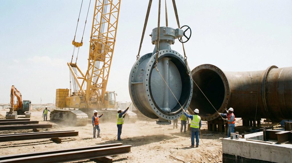
Aligning a massive 48-inch valve poses logistical challenges for installation crews. Double flanged ends simplify this process significantly. The bolt holes align perfectly with pipe flanges, acting as a guide during installation. Cranes lower the valve into position, and bolts slide through easily. This reduces installation time and minimizes the risk of seal damage due to misalignment. Visit our Flanged Butterfly Valve section for heavy-duty options.
| Connection Style | Stability | Install Difficulty | Best For |
|---|---|---|---|
| Wafer | Low | Moderate | Tight Spaces |
| Lug | Medium | Moderate | End-of-Line |
| Double Flanged | High | Easy (Self-aligning) | Large Diameter |
4. When Should You Use Welded Ends?
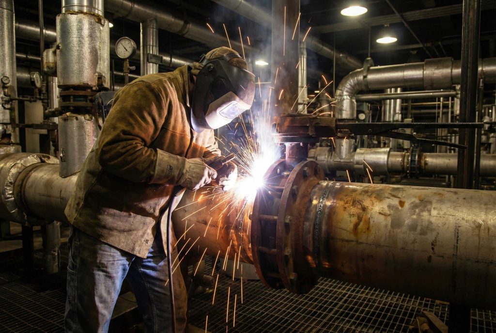
Certain applications tolerate absolutely zero leakage. Butt-weld butterfly valves fuse directly to the pipeline infrastructure. Welders join the beveled valve ends to the pipe, creating a continuous metal interface. This eliminates potential leak paths associated with gaskets or bolted joints. Toxic chemical lines or high-pressure steam systems often mandate welded connections to guarantee personnel safety.
Extreme heat degrades gasket materials rapidly. Welded connections bypass this limitation completely. By removing the reliance on bolts (which relax under thermal cycling) and gaskets, the system handles temperatures exceeding 500°C. Power plants utilize welded valves in critical steam loops where reliability remains non-negotiable.
Ready for the good part? Once welded, maintenance worries related to joint integrity disappear. This solution fits buried pipelines or inaccessible areas where regular maintenance proves impossible. However, selecting welded ends requires confidence that the valve internals will outlast the system or that in-line repair remains feasible.
5. What About Grooved End Connections?
Fire suppression lines demand speed and reliability above all else. Grooved end butterfly valves, often compatible with Victaulic couplings, dominate this sector. The valve body features a machined groove on each end. A split coupling housing engages this groove and the pipe groove, compressing a rubber gasket. This creates a secure seal without welding or heavy flange bolting.
Time means money on construction sites. Installing grooved valves takes a fraction of the time required for flanged units. Two bolts tighten the coupling housing. Think about it: reducing labor hours by 50% significantly impacts project margins. HVAC contractors frequently adopt this method for chilled water loops in commercial buildings.
Pumps and chillers generate noise and vibration during operation. Rigid flange connections transmit this energy throughout the building structure. Grooved couplings offer slight flexibility. This dampening effect isolates equipment vibration, protecting sensitive components and reducing noise levels for building occupants.
| Feature | Grooved End | Flanged End |
|---|---|---|
| Installation Speed | Fast (2 bolts) | Slow (Multiple bolts) |
| Flexibility | Allows movement | Rigid |
| Tools Needed | Wrench | Torque wrench, alignment pins |
| Typical Use | Fire, HVAC | Industrial Process |
6. How Do Sanitary Clamp Connections Function?
Contamination ruins production batches in dairy or pharmaceutical plants. Sanitary butterfly valves utilize Tri-clamp connections. These polished stainless steel ends mate with pipe ferrules using a hinged clamp and a hygienic gasket. The design eliminates crevices where bacteria typically hide. Fluid flows smoothly without stagnation points.
Daily cleaning protocols require frequent equipment teardowns. This is where it gets interesting: Operators disassemble sanitary connections by hand. Unfastening the wing nut on the clamp releases the valve instantly. No wrenches or special tools are necessary. This efficiency supports rigorous sanitation schedules without hindering productivity.
Modern factories automate cleaning processes. Sanitary connections withstand high-pressure spray balls and caustic cleaning solutions used in CIP (Clean-in-Place) cycles. The connection maintains a flush profile with the pipe interior. This guarantees that cleaning agents reach every surface, securing sterility for the next production run.
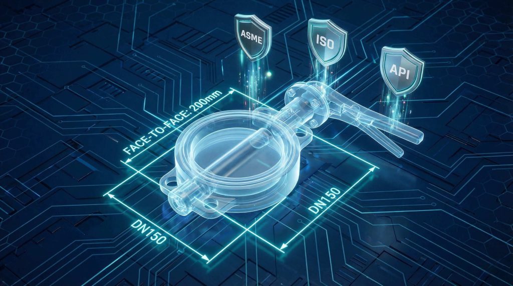
7. Which Standards Govern These Connections?
Global interchangeability relies heavily on standardization. ISO 5752 defines face-to-face dimensions for wafer and flanged butterfly valves. This guarantees a valve from one manufacturer replaces another without piping modifications. API 609 specifically covers valves for oil and gas services, dictating rigid design criteria for lug and wafer types.
North American markets operate on ASME standards. ASME B16.5 outlines flange dimensions, bolt hole patterns, and pressure-temperature ratings. Let’s face it: ignoring these standards leads to installation failures. A Class 150 valve will not bolt to a Class 300 flange. Verify compatibility during the procurement phase.
Space allocation in plant design remains critical. Standards define the “face-to-face” width of the valve. Wafer valves follow “short” series dimensions, while double flanged valves often adhere to “long” series. Knowing these specific measurements prevents surprises when the pipe fitter attempts final assembly.
8. How Do You Install Different Connections?
Misalignment kills valves faster than almost anything else. Pipes must align concentrically before inserting the valve. Forcing a valve into a misaligned gap stresses the body and causes leakage. Leave a small gap between flanges, insert the valve, and insert bolts loosely. Center the unit carefully before final tightening.
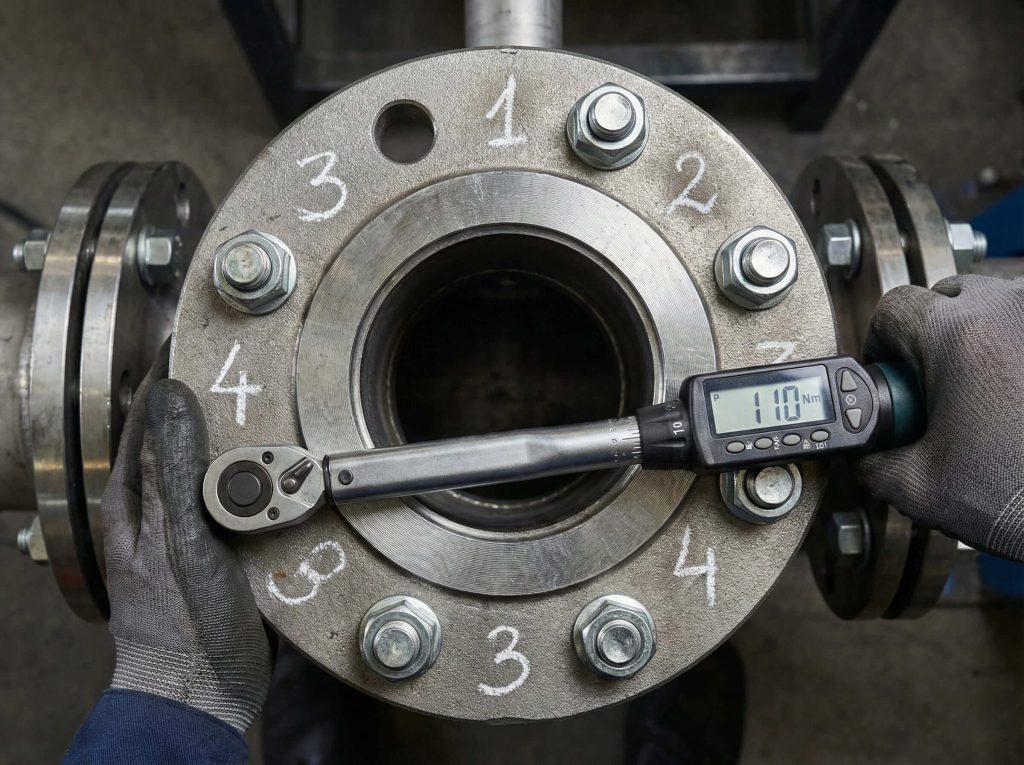
Tightening bolts requires a specific strategy. Here is the bottom line: never tighten bolts sequentially around the circle. Use a star or crisscross pattern. This compresses the gasket evenly. Uneven loading crushes the gasket on one side while leaving gaps on the other. Use a calibrated torque wrench to meet manufacturer specifications.
Rubber-seated butterfly valves often feature an integral liner that acts as a gasket. Adding an extra gasket to these valves causes leaks or damaging compression. Only metal-seated or double-flanged valves typically require separate flange gaskets. Check the manual before installation.
| Step | Action | Precaution |
|---|---|---|
| 1. Align | Center piping | Do not force gap |
| 2. Insert | Place valve & bolts | Watch disc position |
| 3. Tighten | Star pattern | Use torque wrench |
| 4. Test | Cycle valve | Check interference |
9. What Maintenance is Required per Type?
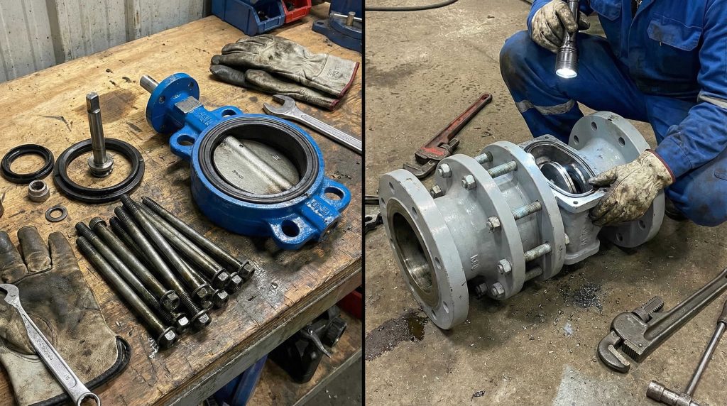
Valves eventually need seat replacement. Wafer valves require draining the line and loosening all flange bolts. The entire valve slides out. Lug valves allow removing just the downstream bolts for inspection, provided the upstream pressure is isolated. This flexibility saves hours during shutdowns.
Over time, elastomers harden or crack. Maintenance technicians remove the valve, disassemble the disc and stem, and replace the seat. Split-body designs facilitate this process. Vulcanized seats, however, usually require replacing the entire valve or sending it for factory refurbishment.
Safety comes first. Before loosening any connection, depressurize the line. It gets better: Lug valves installed for dead-end service act as a safety barrier. However, always use a blind flange downstream for long-term isolation. Never rely solely on the valve disc for personnel safety during downstream work.
10. How to Select the Right Connection?
Operational parameters dictate the choice. High-pressure steam rules out wafer valves with rubber seats. Choose welded or high-performance lug valves. Low-pressure water cooling loops work perfectly with economical wafer types. Always match the valve rating (e.g., PN16, Class 150) to the system maximums.
Corrosive fluids attack metals. A lined wafer valve might offer better protection than a metal flanged valve if the body material isn’t compatible. Sanitary applications demand Tri-clamp ends. Slurries require robust flanged connections that withstand vibration and abrasion.
Projects run on tight margins. Wafer valves offer the lowest entry price. However, factor in lifecycle costs. If a lug valve reduces maintenance downtime by 50%, the higher initial cost pays off. We recommend analyzing total cost of ownership rather than just the sticker price. Contact our Support Team for a detailed cost-benefit analysis.
| Factor | Low Budget | High Pressure | Sanitary | Maintenance Friendly |
|---|---|---|---|---|
| Best Choice | Wafer | Double Flanged | Tri-Clamp | Lug |
Conclusion
Selecting the correct butterfly valve end connection establishes the foundation of system integrity. Wafer types offer economy for general use, while lug styles provide critical maintenance flexibility. Double flanged and welded options serve the most demanding, high-pressure environments. Engineers who master these distinctions secure safer, more efficient, and cost-effective operations. Do not compromise on connection quality. Evaluate your pressure needs, maintenance schedules, and installation constraints carefully.
Ready to optimize your piping system? Browse our extensive catalog or Contact Us today for a custom consultation.
FAQ Section
Q1: What is the best connection for dead-end service?
Lug style butterfly valves serve best for dead-end service. Their threaded inserts allow bolting directly to the upstream flange, holding pressure even when the downstream piping is removed.
Q2: How does a wafer valve differ from a lug valve?
Wafer valves clamp between two flanges using long through-bolts and lack their own bolt holes. Lug valves feature threaded inserts on the body, allowing independent bolting to each flange for greater versatility.
Q3: Can I use wafer valves in high-pressure steam lines?
Generally, no. Standard wafer valves with resilient seats cannot withstand high-pressure steam. High-performance lug or welded valves with metal seats suit these extreme conditions better.
Q4: What standards apply to flange dimensions?
Key standards include ASME B16.5 for North America, EN 1092 for Europe, and JIS B2220 for Japan. ISO 5752 governs the valve’s face-to-face dimensions to ensure global compatibility.
Q5: How do I choose between flanged and lug styles?
Choose lug style if you need compact size with downstream removal capability. Select double flanged styles for very large valves (DN600+) or high-pressure lines where maximum connection stability is required.