A hydraulic butterfly valve is a heavy-duty industrial valve that uses pressurized fluid to rotate a disc for flow regulation or isolation. You are likely struggling with manual valve operations in high-pressure industrial environments where precision and torque are non-negotiable. Traditional valves often fail to provide necessary force, leading to leakage or mechanical bottlenecks in your pipeline. The hydraulic control butterfly valve offers the automated, high-torque performance you need for critical fluid management across complex infrastructure systems.
What is a hydraulic control butterfly valve exactly?
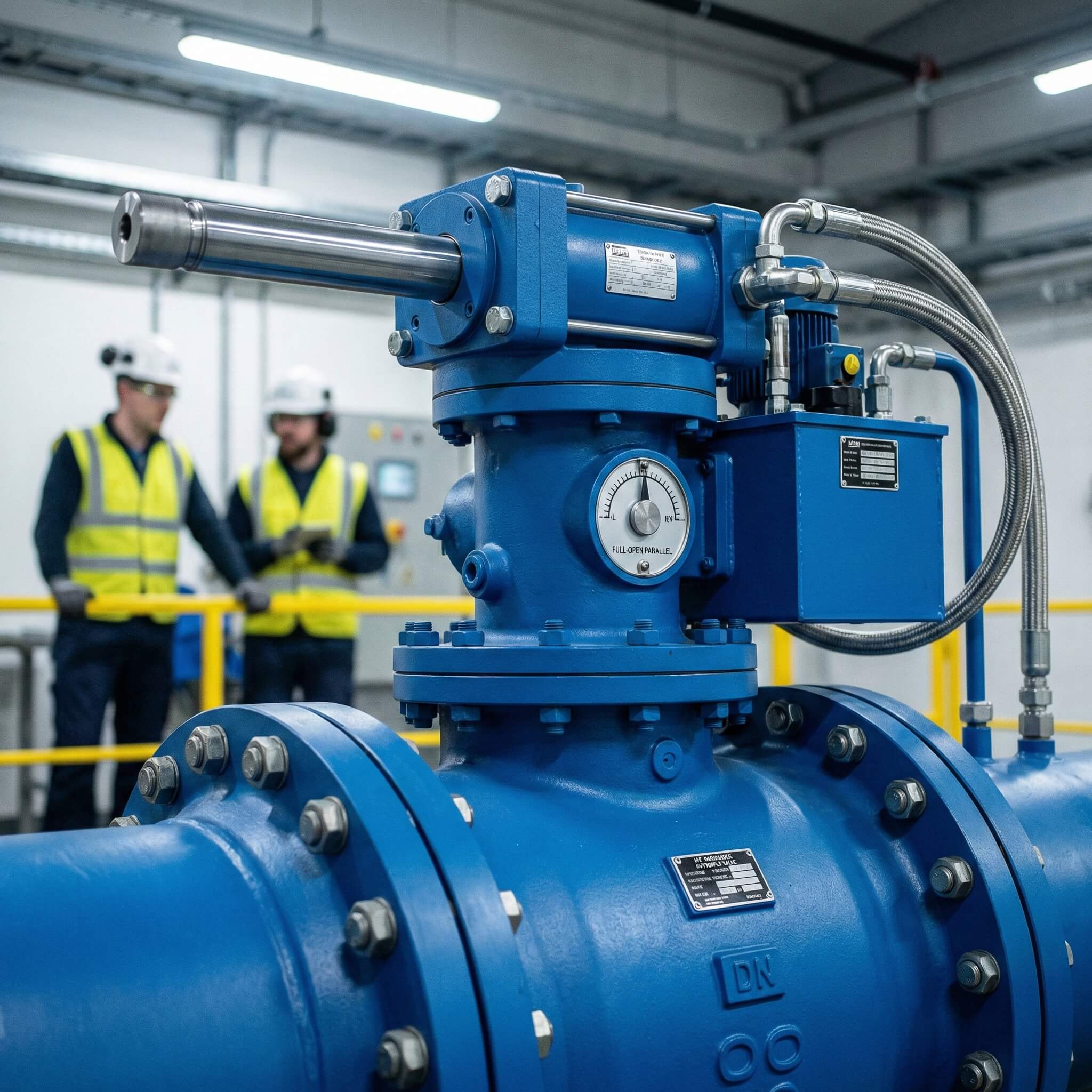
A hydraulic control butterfly valve is an automated flow control device that integrates a standard butterfly valve body with a hydraulic actuator. This system utilizes fluid pressure to generate the massive torque required to rotate the internal disc against high-velocity streams. It is specifically designed for applications where electric or pneumatic systems lack the power density to operate large-diameter pipes.
Core Components and Mechanics
Here is the deal: how does a simple disc stop thousands of gallons of pressurized fluid? The valve consists of a circular disc mounted on a central shaft, which is directly connected to a hydraulic cylinder.
- The actuator receives pressurized oil or hydraulic fluid.
- A piston converts this fluid pressure into linear or rotary force.
- The shaft rotates exactly 90 degrees to open or close the line.
The Role of the Hydraulic Actuator
The actuator is the brain and muscle of the entire assembly, ensuring consistent movement even under extreme differential pressures. You can rely on this component to maintain position without drifting, providing a level of stability that air-powered systems cannot match.
- Key Takeaway: A hydraulic actuator provides the necessary force to overcome high differential pressures that would seize manual or electric alternatives.
| Component | Function | Material Example |
|---|---|---|
| Valve Body | Houses internal parts and connects to pipe | Ductile Iron / Carbon Steel |
| Disc | Rotates to block or allow flow | SS304 / SS316L |
| Hydraulic Actuator | Provides rotatory force via fluid pressure | Carbon Steel Housing |
The integration of high-pressure hydraulics with robust valve bodies ensures a reliable solution for heavy-duty industrial throttling.
How does a hydraulic control butterfly valve function in a pipeline?
A hydraulic control butterfly valve functions by converting hydraulic energy into mechanical movement to position a disc within the flow path. When the control system triggers the hydraulic pump, fluid enters the actuator cylinder, initiating a precise quarter-turn rotation of the valve stem. This operation allows you to manage fluid flow with extreme accuracy and speed in large-scale piping networks.
Conversion of Fluid Pressure to Mechanical Energy
The process starts with hydraulic fluid being pumped into the actuator chambers at high pressure. This creates a powerful force that acts upon a piston or a rack-and-pinion mechanism inside the actuator housing.
- High-pressure oil pushes against the internal piston.
- Linear motion is converted to rotary motion via a scotch-yoke or gear system.
- The generated torque allows for smooth opening against heavy flow resistance.
Precise Quarter-Turn Disc Rotation
Look: the disc only needs to move 90 degrees to go from fully closed to fully open. When the disc is parallel to the flow, the valve is open; when perpendicular, it provides a tight seal against the valve seat.
- Key Takeaway: The quarter-turn mechanism ensures rapid response times, which is essential for preventing water hammer in large-scale water treatment networks.
| Stage | Action | Result |
|---|---|---|
| Actuation | Fluid enters cylinder | Internal pressure builds rapidly |
| Transmission | Piston moves shaft | Stem rotates exactly 90° |
| Termination | Disc meets seat | Flow is fully obstructed or allowed |
The mechanical simplicity of the quarter-turn design, powered by hydraulics, results in a system that is both fast and incredibly powerful.
Why should you choose a hydraulic control butterfly valve over manual options?
Choosing a hydraulic control butterfly valve is a strategic decision for any facility manager looking to eliminate manual labor and human error in high-torque scenarios. In critical applications, the sheer force required to seat a large-diameter valve is often beyond the physical capability of a manual operator. Automated hydraulic systems ensure that your valves operate exactly when needed, regardless of external conditions.
Superior Torque and Force Density
The best part? Hydraulic systems provide the highest torque-to-size ratio available in the valve industry today. You can operate valves as large as DN3000 with minimal effort using a compact hydraulic unit that fits in tight spaces.
- Consistently provides maximum sealing force.
- Ability to break through sediment or mineral scale.
- High pressure tolerance up to PN40 standards.
Precision Positioning and Control
Precision is everything when you are throttling flow in a chemical processing or power plant. Hydraulic actuators allow for infinite positioning, meaning you can open the valve to a specific percentage with high repeatability.
- Key Takeaway: Hydraulic control provides unmatched accuracy for throttling applications where flow regulation is as important as shut-off.
| Feature | Manual Valve | Hydraulic Valve |
|---|---|---|
| Operation Speed | Slow and labor-intensive | Fast and automated |
| Torque Capacity | Human-limited | Industry-leading (Up to PN40) |
| Remote Control | Impossible | Fully compatible with SCADA |
By transitioning from manual to hydraulic control, you gain significant operational efficiency while reducing the risk of mechanical failure.
What are the primary benefits of hydraulic control butterfly valve systems?
A hydraulic control butterfly valve provides a level of reliability and stability that is difficult to match with electric or pneumatic alternatives. Because hydraulic fluid is non-compressible, the movement of the valve is extremely stable and free from the “jumpy” motion often seen in air-powered systems. This makes them the ideal choice for high-stakes environments where vibration or sudden movement could damage downstream equipment.
Failure Protection and Fail-Safe Operations
What happens when the power goes out? Hydraulic systems often incorporate a weighted lever or a pressurized accumulator that automatically closes the valve during a power failure.
- Provides “fail-closed” or “fail-open” security.
- Protects downstream equipment from sudden pressure surges.
- Maintains position without an active external power source.
Space-Saving and Compact Design
You might think such power requires a massive footprint, but the opposite is true for hydraulic systems. Hydraulic actuators are significantly smaller than electric or pneumatic actuators of the same torque rating.
- Fits into tight manifold spaces and underground vaults.
- Reductions in weight minimize stress on your piping system.
- Key Takeaway: The compact nature and fail-safe capabilities make these valves the gold standard for high-risk industrial environments.
| Benefit | Description | Impact |
|---|---|---|
| Stability | Non-compressible fluid use | Smooth, vibration-free motion |
| Safety | Fail-safe mechanisms | Prevents system catastrophes |
| Footprint | High force density | Saves valuable installation space |
These strategic benefits allow you to design more compact and safer fluid control systems without sacrificing power or reliability.
Where is a hydraulic control butterfly valve most commonly applied?
You will find the hydraulic control butterfly valve in sectors where fluid volumes are massive and the cost of operational failure is astronomical. From massive hydroelectric dams to offshore oil platforms, these valves handle the “heavy lifting” of the industrial fluid control world. They are the preferred choice whenever you need to manage large-diameter pipes with absolute reliability.
Oil and Gas Midstream Operations
In the oil and gas sector, you need equipment that can handle viscous media and extreme environmental pressure. These valves are frequently used in pumping stations to manage the flow of crude oil through cross-country pipelines.
- Excellent for emergency shut-down (ESD) scenarios.
- High resistance to harsh outdoor and offshore environments.
- Corrosion-resistant materials like SS316 are standard.
Municipal Water and Wastewater Treatment
Look at any modern city’s water network, and you will see these hydraulic valves at work. They are essential for regulating the intake of raw water and the discharge of treated effluent in large-scale municipal facilities.
- Standardized for sizes ranging from DN50 to DN3000.
- WRAS-approved options ensure safety for potable water.
- Key Takeaway: Their ability to manage large-diameter pipes makes them indispensable for municipal infrastructure and urban water safety.
| Industry | Primary Use Case | Critical Requirement |
|---|---|---|
| Oil & Gas | Pipeline Surge Control | High Pressure/ESD Support |
| Water Works | Reservoir Management | Large Diameter/Durability |
| Chemical | Process Throttling | Precision/Corrosion Resistance |
The versatility of hydraulic actuation makes these valves a cornerstone for both critical utility services and high-profit industrial production.
How do you install and maintain a hydraulic control butterfly valve?
Installing and maintaining a hydraulic control butterfly valve requires careful attention to alignment and fluid cleanliness to ensure a long service life. Because these systems rely on high-pressure hydraulics, you must follow specific torque sequences and filtration standards during both initial setup and routine checks. Regular maintenance is the key to preventing the most common causes of industrial valve failure.
Installation Best Practices
Before you begin, ensure the pipe flanges are clean and perfectly aligned to prevent uneven stress on the valve body. You should mount the hydraulic actuator in a position that allows easy access for fluid refills and seal inspections.
- Verify flange standards match (ANSI, DIN, or JIS).
- Ensure the disc has enough clearance to rotate fully.
- Test the hydraulic lines for leaks before full pressurization.
Monitoring Hydraulic Fluid and Seals
Look: contaminated hydraulic oil is the leading cause of actuator failure in industrial settings. You must regularly check the clarity and viscosity of the fluid to prevent internal wear on the piston and seals.
- Monthly visual inspections for external oil leaks.
- Annual testing for particulates in the hydraulic fluid.
- Key Takeaway: Proactive maintenance focusing on fluid cleanliness and seal integrity can extend the operational life of your valve to over 25 years.
| Task | Frequency | Objective |
|---|---|---|
| Fluid Inspection | Quarterly | Prevent pump and piston wear |
| Seal Replacement | Bi-Annually | Maintain system pressure |
| Calibration | Annually | Ensure 100% leak-proof shut-off |
Consistent adherence to these maintenance steps ensures that your automated system remains responsive and leak-free throughout its lifecycle.
What common issues affect hydraulic control butterfly valve performance?
The most common issues affecting hydraulic control butterfly valve performance involve hydraulic fluid contamination and internal seal degradation. While these valves are incredibly robust, they are sensitive to the quality of the medium used to power the actuator. If the hydraulic oil contains debris, it can score the internal cylinder walls, leading to pressure loss and reduced torque output.
Fluid Contamination and Filter Clogging
Here is the deal: if your hydraulic fluid is dirty, your valve will eventually fail to move. Small particles can clog the control valves or damage the pump, resulting in “jumpy” movement or a total lack of response.
- Use high-quality filters in the hydraulic circuit.
- Change the oil according to the manufacturer’s schedule.
- Monitor for signs of aeration or foaming in the fluid.
Seal Wear and Internal Bypassing
Think about the pressure these seals endure every day. Over time, elastomer seals can harden or wear down, allowing hydraulic fluid to bypass the piston and reducing the force applied to the valve stem.
- Regularly inspect the piston rod for scoring or damage.
- Listen for internal “hissing” sounds that indicate a bypass.
- Key Takeaway: Replacing seals before they fail is significantly cheaper than repairing a damaged actuator cylinder or dealing with an unscheduled shutdown.
| Issue | Symptom | Solution |
|---|---|---|
| Contamination | Jerky or slow movement | Flush fluid and replace filters |
| Seal Leakage | External oil visible | Replace O-rings and gaskets |
| Calibration Drift | Incomplete valve closing | Reset limit switches/actuator stroke |
By identifying these performance bottlenecks early, you can maintain the high precision and power density that hydraulic systems are known for.
What materials are best for a hydraulic control butterfly valve?
The best materials for a hydraulic control butterfly valve depend entirely on the chemistry and temperature of the media you are transporting. While ductile iron is the standard for water applications, you will need stainless steel or exotic alloys for corrosive chemicals or abrasive slurries. Choosing the right material ensures that the valve body and internal disc can withstand the rigors of your specific industrial environment.
Disc and Seat Material Selection
Precision starts with the contact points between the disc and the seat. For general water service, EPDM or NBR seats paired with stainless steel discs offer an excellent balance of cost and performance.
- SS316L discs provide superior corrosion resistance for chemicals.
- PTFE seats are required for highly aggressive media.
- Aluminum Bronze is the gold standard for marine and seawater use.
Body Construction and Coating
Look: the exterior of the valve needs as much protection as the interior. Modern hydraulic valves use high-quality coatings like fusion-bonded epoxy to prevent rust and external corrosion in damp environments.
- Ductile iron bodies offer high strength for municipal use.
- Carbon steel is preferred for high-temperature oil and gas.
- Key Takeaway: Matching the valve’s metallurgy and seal type to your specific fluid characteristics is the most effective way to prevent premature failure.
| Component | Common Material | Best Application |
|---|---|---|
| Valve Body | Ductile Iron (DI) | Water and Wastewater |
| Valve Disc | SS316L | Corrosive / Chemical |
| Valve Seat | EPDM / PTFE | Potable Water / Harsh Acids |
Careful material selection during the procurement phase will directly impact the total cost of ownership and the reliability of your pipeline.
How do you select the right hydraulic control butterfly valve?
To select the right hydraulic control butterfly valve, you must evaluate the maximum operating pressure, the flow velocity, and the specific characteristics of the media. A mismatch in pressure ratings (PN10 vs. PN40) or flange standards can lead to catastrophic leaks or installation delays. You should always consult with a technical expert to ensure the valve’s torque output matches the resistance of your pipeline.
Sizing and Pressure Rating Analysis
The first step is matching the valve size to your existing pipe diameter, typically ranging from DN50 to DN3000. You must also ensure the valve’s pressure rating (PN) exceeds the highest possible surge pressure in your system.
- Check flange compatibility (ANSI, DIN, JIS).
- Calculate the required torque based on the fluid velocity.
- Ensure the valve’s temperature range covers your process needs.
Evaluating Application-Specific Needs
Here is the bottom line: not all butterfly valves are created equal. If you are handling abrasive mining slurries, you need a valve designed for high wear resistance, whereas a municipal project might prioritize WRAS certification.
- Consider “fail-safe” requirements (fail-open or fail-closed).
- Verify the need for remote SCADA feedback sensors.
- Key Takeaway: Always allow a 1.5x safety margin on pressure ratings to account for unexpected surges or water hammer events.
| Selection Factor | Consideration | Recommendation |
|---|---|---|
| Pressure | Max surge capacity | Select PN16 or PN25 for most utilities |
| Media | Viscosity and Chemistry | Use SS304/316 for chemical safety |
| Automation | Control system interface | Ensure actuator is SCADA compatible |
A thorough technical evaluation during the selection process eliminates the risk of operational bottlenecks and ensures long-term system integrity.
What safety features define a modern hydraulic control butterfly valve?
Modern safety features in a hydraulic control butterfly valve include rapid emergency shut-off mechanisms and rigorous hydrostatic testing to ensure structural integrity. These valves are no longer just simple gates; they are intelligent safety devices that protect your billion-dollar infrastructure from catastrophic failures. By integrating advanced sensors and fail-safe hardware, you can automate your safety protocols with absolute confidence.
Emergency Shut-Off and Fast Actuation
In the event of a pipe burst or system failure, you need the valve to close instantly to prevent massive fluid loss. Many hydraulic systems are equipped with “fast-acting” solenoids that can trigger a full 90-degree closure in under two seconds.
- Triggered automatically by pressure drop sensors.
- Can be operated remotely from a central control room.
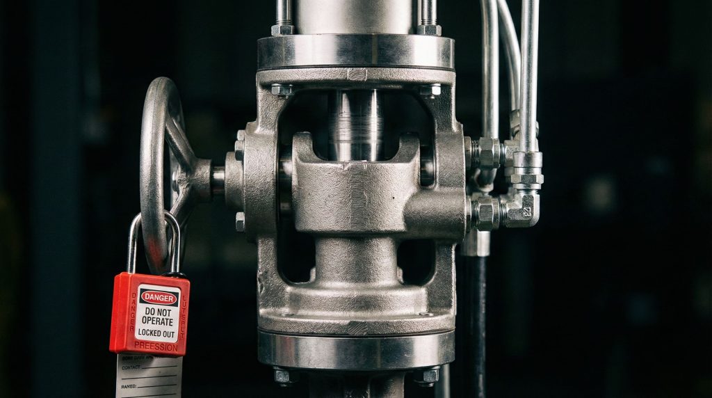
- Features mechanical overrides for manual operation during emergencies.
High-Pressure Tolerance and Quality Standards
Safety is also about the physical strength of the valve housing. Quality manufacturers subject every valve to hydrostatic testing at 1.5 times the working pressure to ensure there are no casting defects or potential leak points.
- Compliance with API 598 and ISO 5208 testing standards.
- ISO 9001 certified manufacturing processes.
- Key Takeaway: The combination of rapid automated response and rigorous pressure testing ensures your facility remains safe even under extreme operational stress.
| Feature | Function | Safety Benefit |
|---|---|---|
| Fast-Close Solenoid | Rapid 90° actuation | Limits spill volume and damage |
| Hydrostatic Test | Structural verification | Guaranteed leak-proof performance |
| Remote Feedback | Real-time monitoring | Eliminates “blind” valve operation |
These modern safety protocols turn your flow control system into a proactive shield against environmental hazards and mechanical failures.
Conclusion
The hydraulic butterfly valve is a powerhouse of industrial fluid control, offering the torque, stability, and precision required for the world’s most demanding applications. By utilizing non-compressible fluid pressure, these valves solve the challenges of high-pressure leakage and manual operation bottlenecks that plague traditional systems. From municipal water treatment to offshore oil and gas operations, this technology ensures your infrastructure remains efficient, safe, and fully automated. To optimize your pipeline with precision-engineered solutions and get a custom technical consultation for your project, contact us today.
FAQ
- Can I use a hydraulic control butterfly valve for high-temperature steam?
Yes, but you must select a metal-seated design and specialized high-temperature hydraulic fluid to ensure the actuator seals do not degrade from thermal transfer. - What’s the best way to prevent leaks in hydraulic actuators?
The most effective method is maintaining strict fluid cleanliness standards through regular filtration and replacing internal seals at the first sign of pressure loss. - Can I automate existing manual butterfly valves with hydraulic systems?
Yes, you can typically retrofit a manual valve with a hydraulic actuator using a standardized ISO 5211 mounting kit that matches the valve’s top flange. - How do I know if my hydraulic valve needs recalibration?
If you notice a “seat scrubbing” sound or if the valve fails to reach a zero-leakage shut-off, it is likely that the actuator’s 90-degree limit switches need adjustment. - Is it better to use a hydraulic valve or a pneumatic one for large pipes?
Hydraulic is generally better for large pipes (over 24 inches) because hydraulic fluid provides significantly higher torque and much smoother motion control than compressed air.