
In the high-stakes world of industrial fluid control, a single millimeter of discrepancy in valve sizing can escalate from a minor installation annoyance to a catastrophic system failure. Consider this scenario: you procure a batch of high-performance valves for a critical municipal water project, only to discover during a scheduled shutdown that the face-to-face dimensions drift slightly from the existing piping layout. This oversight triggers a domino effect of extended downtime, emergency retrofitting costs, and potential safety hazards that far outweigh the initial hardware investment. This guide dissects the complexities of butterfly valve sizing, global standards, and fitment strategies to ensure your engineering decisions deliver long-term reliability.
The Critical Role of Accurate Butterfly Valve Standard Dimensions
Correctly interpreting dimension charts is not just about physical fitment; it is about ensuring hydrodynamic efficiency and long-term seal integrity across your specific piping system. Here is the reality: neglecting the correlation between nominal pipe size (NPS) and internal disc clearance can create flow turbulence that erodes downstream components.
Why do minor dimensional variations cause major failures?
Even a slight mismatch in the bore dimension or disc chord can lead to mechanical interference with the mating pipe, preventing the valve from fully opening or closing. It boils down to this: physical obstruction damages the sealing edge instantly, rendering the valve useless before it even operates.
- Consequences of Inaccuracy:
- Permanent disc edge damage
- compromised flange sealing surface
- Increased actuator torque requirements
- Catastrophic seat leakage
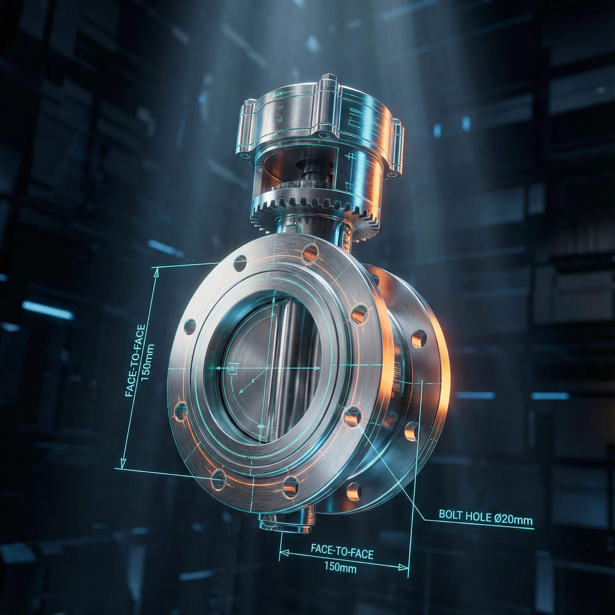
How does face-to-face length impact system compatibility?
The face-to-face (FTF) dimension determines whether a valve can physically slide into the gap between two pipe flanges without requiring costly pipe modifications. You typically find: replacing a gate valve with a butterfly valve often requires a spool piece because the butterfly valve’s FTF is significantly shorter.
- FTF Considerations:
- ISO 5752 Series 20 (Short)
- API 609 Category A vs. B
- Retrofitting space constraints
- Gasket compression allowance
What is the relationship between pressure rating and body thickness?
Higher pressure classes, such as Class 600, demand thicker wall sections and reinforced flange faces to withstand the internal forces without deformation. You might be surprised to learn: a Class 150 valve and a Class 300 valve of the same bore size often have significantly different external footprints and bolting patterns.
- Pressure-Dimension Correlation:
- Thicker bodies for Class 300/600
- Larger bolt circle diameters (BCD)
- Increased stem diameter for torque
- Heavier overall weight load
Key Takeaway
Mastering the nuances of dimensional tolerance allows you to optimize space claims and prevent costly on-site modifications, ensuring that the valve you order is the valve that fits.
Navigating the alphabet soup of international standards is essential for ensuring interchangeability and compliance in global projects. The bottom line is: reliance on a single standard without cross-referencing can lead to procurement errors when integrating components from different regions.
What defines the API 609 Category A and B distinction?
Category A covers concentric, resilient-seated valves typical for water works, while Category B addresses offset, metal-seated valves for severe service conditions. Here is the kicker: mistaking a Category A dimension for a high-performance Category B application will result in immediate installation failure due to differing face-to-face lengths.
- API 609 Categories:
- Category A: Concentric, rubber-lined, compact.
- Category B: Offset, high-performance, robust.
- Application: Water vs. Hydrocarbons.
- FTF Standards: Differ significantly.
Does ISO 5752 ensure universal flange compatibility?
ISO 5752 strictly standardizes the valve’s face-to-face length (basic series), but it does not automatically dictate the flange drilling pattern. You need to know: you must explicitly verify that the bolt circle diameter aligns with your specific DIN PN10/16 or ANSI Class 150 mating flanges.
- ISO 5752 Nuances:
- Defines body length (e.g., Series 20).
- Does not define drilling (see EN 1092).
- Common in European projects.
- Often interchangeable with API 609 Wafer.
How do ASME B16.34 ratings influence physical valve size?
This standard dictates minimum wall thickness requirements based on the material’s pressure-temperature rating to ensure safety under stress. The truth is: a valve meeting ASME B16.34 will likely be heavier and more robust dimensionally than a non-compliant generic valve.
- ASME B16.34 Impacts:
- Mandatory minimum wall thickness.
- Flange thickness requirements.
- Reinforcement for high-temp service.
- Strict NDT testing protocols.
Expert Analysis: Understanding the cross-compatibility of these standards is crucial for global sourcing. While API 609 is the bible for Oil & Gas, ISO 5752 is the lingua franca for general industry.
Standard Scope Key Dimensional Focus Typical Application API 609 Oil, Gas, Petrochem Face-to-Face, Flange Bolting High-performance Lug/Wafer ISO 5752 General Industrial Face-to-Face Series (e.g., Series 20) Inter-standard compatibility ASME B16.34 Heavy Industrial Wall Thickness, P-T Ratings High Pressure/Temp Safety AWWA C504 Water Works Short body, rubber seated Municipal Water/Wastewater
Key Takeaway
Aligning your specifications with the correct standard category (API 609 Cat A vs. B or ISO Series 20) eliminates the risk of receiving valves that technically “meet standard” but fail to fit your specific pipeline gap.
Measuring Butterfly Valve Dimensions for Precise Fitment
Precision in measurement prevents the costly “measure once, cut twice” scenario that plagues on-site installations. Let’s face it: relying on nominal datasheet values without field verification of existing pipe spread often leads to installation delays.
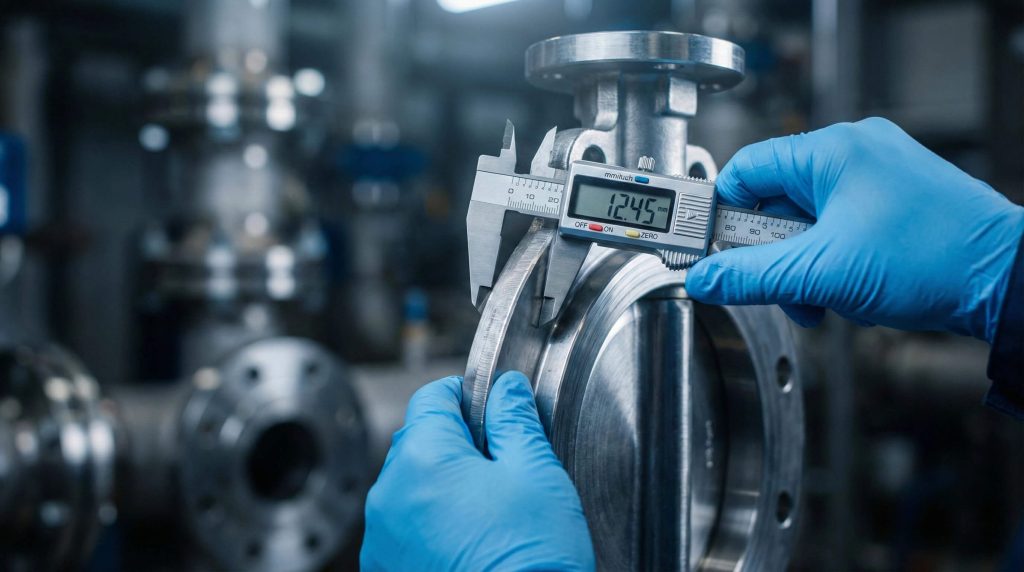
What are the critical measurement points for replacement valves?
You must measure from the extreme face of the inlet flange to the extreme face of the outlet flange, excluding any protruding gaskets or liners unless specified. The secret is: using a calibrated caliper rather than a tape measure ensures you catch the sub-millimeter variances that matter in rigid piping systems.
- Measurement Checklist:
- Inlet-to-Outlet Length (FTF).
- Nominal Bore (ID) vs. Pipe Schedule ID.
- Bolt Hole Diameter and Count.
- Flange Outer Diameter (OD).
How do you accurately measure bolt circle diameter (PCD)?
Measure the distance from the center of one bolt hole to the center of the hole directly opposite it across the flange face. But here is the catch: if the holes are not directly opposite (odd number of holes), you must calculate the diameter using the chord length between adjacent holes.
- PCD Methods:
- Center-to-Center (Even holes).
- Mathematical calculation (Odd holes).
- Use a flange template.
- Verify against standard tables (DIN/ANSI).
Why must you account for liner compression during measurement?
For resilient-seated valves, the rubber liner often extends over the flange face to act as a gasket, adding to the compressed installed length. Here is the deal: failure to account for the uncompressed vs. compressed liner thickness can result in flange bolts that are too short or excessive stress on the piping.
- Liner Factors:
- Uncompressed thickness is greater.
- Acts as integral gasket.
- Requires specific torque to seat.
- Affects final bolt length.
Key Takeaway
Accurate field measurement that accounts for liner compression and pipe schedule variances ensures that the valve you order drops seamlessly into the line without forcing.
Comparing Wafer, Lug, and Flanged Connection Dimensions
The connection type significantly dictates the physical envelope of the valve and its ease of installation within the bolt circle. Think about it: while a wafer valve saves space, a flanged valve offers structural rigidity that changes the dimensional footprint entirely.
Why are wafer valve dimensions distinct from lug styles?
Wafer valves are designed to be sandwiched between flanges, relying on the compressive force of the surrounding bolts to hold them in place. But there is a catch: they lack the threaded inserts of lug valves, meaning their body width is strictly defined by the face-to-face standard without protruding ears.
- Wafer Characteristics:
- Shortest face-to-face.
- Centering holes only.
- Lightweight body.
- Sandwiched installation.
When do double-flanged dimensions become necessary?
Double-flanged dimensions are necessary for large-diameter or high-pressure lines (DN600+) where the valve body must withstand significant pipe stress. You need to know: the increased face-to-face length of flanged valves provides necessary room for robust disc structures and heavier wall thickness.
- Flanged Benefits:
- Independent bolting.
- Highest structural integrity.
- Suitable for dead-end service.
- Longer FTF (ISO 5752 Series 13/14).
How do lug threaded inserts affect installation clearance?
Lug valves feature threaded holes that match the mating flange patterns, requiring bolts to be inserted from both sides or pass through if threaded through-holes are used. You might be surprised to learn: this requires precise alignment of the pipeline flanges, as you cannot simply “slide” the bolts through like a wafer valve.
- Lug Considerations:
- Thread compatibility (UNC vs Metric).
- Bolt length calculation is critical.
- Allows downstream piping removal.
- Precise alignment required.
Expert Analysis: Wafer valves offer the best space efficiency, but Lug and Flanged types provide necessary isolation capabilities.
Valve Type Face-to-Face Profile Installation Space Structural Load Capacity Wafer Shortest (Compact) Minimal Low (Transfers load to bolts) Lug Medium (Standard) Moderate Medium (Body takes thread load) Flanged Longest (Robust) Maximum High (Independent flange support)
Key Takeaway
Choosing the right connection style is a trade-off between spatial efficiency and structural security, with each type demanding specific dimensional clearances for bolts and actuators.
Impact of Material Selection on Butterfly Valve Dimensions
The choice of material does not just dictate chemical resistance; it fundamentally alters the structural thickness required to meet pressure ratings. Here is the reality: a ductile iron body and a stainless steel body of the same rating may have subtle dimensional differences due to casting tolerances and strength requirements.
While the standard (e.g., API 609) sets the nominal dimension, casting tolerances for ductile iron vs. stainless steel (CF8M) can vary slightly. The truth is: stainless steel offers higher tensile strength, potentially allowing for thinner walls in non-critical areas, but the sealing dimensions must remain identical.
- Material Variances:
- Casting shrinkage rates differ.
- Wall thickness requirements.
- Machining tolerances.
- Weight differences.
How does lining thickness alter the effective internal bore?
Thick PTFE or rubber linings reduce the effective flow coefficient (Cv) by narrowing the internal diameter compared to an unlined metal valve. It turns out: ignoring this reduction can lead to undersized flow capacity, increasing pump energy costs and system pressure drop.
- Lining Effects:
- Reduces ID (Internal Diameter).
- Increases turbulence potential.
- Requires compatible pipe schedule.
- Cv value recalculation needed.
Why do high-temperature materials require extended dimensional envelopes?
High-temperature valves often require extended stems or finned bonnets to dissipate heat and protect the actuator. Consider this: these vertical dimension additions must be calculated to ensure the valve fits within the physical vertical constraints of the plant layout.
- Thermal Design:
- Extended bonnets.
- Cooling fins.
- Actuator standoff brackets.
- Increased overhead clearance.
Key Takeaway
Material properties directly influence wall thickness and liner intrusion, meaning high-performance material selection requires a re-verification of effective flow dimensions and external clearances.
Understanding Offset vs. Concentric Valve Dimensional Variances
The internal geometry of the valve disc dictates the external body size required to house the mechanism. It boils down to this: simple concentric valves are slim, while offset valves require more robust bodies to accommodate the camming action of the shaft.
How does the triple offset design change the face-to-face profile?
Triple offset valves (TOV) utilize a conical sealing geometry that requires a thicker body to accommodate the angled seat and robust disc. Here is the kicker: a TOV face-to-face dimension is often significantly longer than a standard concentric rubber-seated valve, making direct swapping impossible without piping changes.
- TOV Dimensions:
- Longer body length (API 609 Cat B).
- Offset shaft position.
- Laminated seal thickness.
- Requires more installation space.
Why are concentric valves typically narrower than offset types?
Concentric valves have the stem passing directly through the centerline of the disc, allowing for a very compact, wafer-thin profile. The bottom line is: this design is optimized for space-saving in low-pressure water and air applications where a bubble-tight metal seal is not required.
- Concentric Profile:
- Shortest FTF available.
- Simple disc geometry.
- Resilient seat integration.
- Ideal for tight skids.
Do double offset valves fit into standard wafer spaces?
Some double offset valves are designed to fit ISO 5752 short patterns, but many high-performance variants require API 609 Category B dimensions. You need to know: assume nothing; always verify if the “high performance” valve you are ordering is a direct drop-in replacement for a standard wafer valve.
- Double Offset Fitment:
- Check API 609 Category.
- Verify disc protrusion.
- Confirm flange clearance.
- Check actuator mounting height.
Expert Analysis: The shift from concentric to offset design improves performance but demands more space.
Valve Design API Category Typical FTF Standard Main Advantage Concentric Category A ISO 5752 Series 20 Compact, Cost-effective Double Offset Category B API 609 / ISO 5752 Lower friction, Higher Pressure Triple Offset Category B API 609 / ASME B16.10 Zero Leakage, Metal Seated
Key Takeaway
Mastering the nuances of concentric versus offset dimensions allows you to optimize space claims without compromising pressure handling capabilities or flow coefficients.
Installation Guidelines to Ensure Dimensional Integrity
Even the perfectly sized valve can fail if the installation process ignores dimensional alignment and spacing. Consider this: forcing a valve into a gap that is too narrow or misaligned introduces stress that warps the body and compromises the shaft seal.
How much disc clearance is required to prevent interference?
The disc of a butterfly valve protrudes into the pipeline when open, requiring the adjacent pipe or flange to be free of obstructions. But here is the catch: heavy schedule pipes (e.g., Schedule 80) or lined piping may have a smaller ID that interferes with the disc edge, preventing full opening.
- Clearance Checks:
- Check Pipe Schedule ID.
- Measure Disc Chord.
- Verify Check Valve proximity.
- Use spacers if needed.
What is the correct bolt tightening sequence to maintain alignment?
To maintain the dimensional integrity of the face-to-face seal, bolts must be tightened in a star pattern to compress the liner evenly. Here is the deal: uneven tightening distorts the valve body dimensionally, leading to immediate leaks or increased operating torque due to body twisting.
- Tightening Protocol:
- Hand-tighten first.
- Star/Criss-cross pattern.
- Incremental torque application.
- Check flange parallelism.
Why is flange parallelism critical for maintaining dimension specs?
If the mating flanges are not parallel, tightening the bolts will warp the valve body to match the pipe misalignment. You might be surprised to learn: this induced stress is a leading cause of premature stem leakage and seized discs in butterfly valves.
- Parallelism Issues:
- Induces body torque/twist.
- Misaligns stem and bush.
- Causes uneven liner compression.
- Voiding manufacturer warranty.
Key Takeaway
Verifying the “interference dimension”—where the disc enters the pipe—is just as critical as the external face-to-face measurement to prevent mechanical binding during operation.
Troubleshooting Common Butterfly Valve Dimension Mismatches
Field issues often stem from subtle dimensional mismatches that are overlooked during the procurement phase. Let’s be honest: “standard” does not always mean “universal,” and assumptions about fitment are the root cause of most site delays.
Why does the disc strike the pipe wall upon opening?
This usually happens when a standard valve is installed in heavy-wall pipe or piping with thick internal lining. The bottom line is: the valve’s “chord dimension” exceeds the pipe’s effective internal diameter, physically stopping the disc from rotating to 90 degrees.
- Disc Strike Causes:
- Schedule 80/160 pipe.
- Cement/Rubber lined pipe.
- Installation of Check Valve too close.
- Debris accumulation.
Can you install an ISO valve into an ANSI piping system?
While the face-to-face dimension might match (e.g., Wafer Short), the bolt hole locations often do not align. You need to know: an ISO PN10/16 flange has a different Bolt Circle Diameter (BCD) and hole count compared to an ANSI Class 150 flange, making them incompatible without special drilling.
- Standard Mismatch:
- Different Bolt Circle Diameter.
- Metric vs Imperial bolts.
- Different hole counts (e.g., 4 vs 8).
- Gasket surface variance.
How do you resolve face-to-face gaps during retrofitting?
If the new butterfly valve is narrower than the old gate valve it replaces, you cannot simply pull the pipes together. The secret is: you must install a “spool piece” or spacer ring to bridge the dimensional gap and ensure stress-free installation.
- Retrofit Solutions:
- Machined spool pieces.
- Flange spacers.
- Dismantling joints.
- Re-piping (Costly).
Expert Analysis: Most “valve failures” are actually “selection failures.” The table below highlights where dimensional mismatches cause operational issues.
Symptom Probable Dimensional Cause Solution Disc strikes pipe Pipe Schedule ID is too small for Disc Chord Check interference; chamfer pipe or use spacer Flange Leakage Mating flange ID > Valve Liner sealing face Use correct flange type (Weld Neck vs Slip-on) Cannot Insert Bolts Bolt Circle Diameter (BCD) mismatch Verify drilling standard (PN10 vs Class 150) Stem Leakage Side-load due to misalignment/short pipe gap Re-align piping; do not force fit
Key Takeaway
Proactive dimensional troubleshooting involves validating not just the valve, but the mating components (flanges, gaskets, bolts) to ensure a holistic mechanical fit.
Conclusion
Precise adherence to butterfly valve standard dimensions is the bedrock of a safe, efficient, and long-lasting fluid control system. By understanding the nuances of API and ISO standards, accounting for material variables, and verifying installation clearances, you move from reactive troubleshooting to proactive engineering excellence. Avoiding the hidden costs of misalignment and incompatibility protects not just your budget, but the operational integrity of your entire facility.
At RUITO, we leverage over 20 years of manufacturing expertise to bridge the gap between complex international standards and your specific project needs. We don’t just sell valves; we provide the dimensional certainty and technical backing that rigorous engineering demands. Whether you need a standard API 609 wafer valve or a custom high-performance solution, our team ensures the perfect fit every time.
Ready to eliminate fitment risks? Contact our technical team today for a precise consultation on your project’s dimensional requirements.
FAQ
Q: Can I use an ISO 5752 Series 20 valve to replace an API 609 wafer valve?
A: Generally, yes, but verify the specific pressure rating and flange compatibility. Both standards often share identical face-to-face dimensions for wafer valves in common sizes, but the bolt hole tolerance and centering diameter must be confirmed against your mating flanges.
Q: How do I know if the butterfly valve disc will hit my pipe wall?
A: You must compare the valve’s “chord dimension” (disc clearance) against the actual Internal Diameter (ID) of your pipe schedule. If the pipe is Schedule 80 or lined, the ID may be too narrow, requiring a spacer or a check of the manufacturer’s minimum pipe ID specification.
Q: What is the best way to measure a valve for replacement if the tag is missing?
A: Measure the Face-to-Face (FTF) length and the Bolt Circle Diameter (PCD). These two metrics, combined with the number of bolt holes and the bore diameter, are usually sufficient to identify the valve’s standard (DIN vs. ANSI) and pressure class for a correct replacement.
Q: Does the face-to-face dimension change between metal-seated and soft-seated valves?
A: Yes, it frequently does. Metal-seated high-performance valves often have longer face-to-face dimensions (API 609 Category B) to accommodate the offset mechanism, whereas soft-seated concentric valves (Category A) are typically narrower.
Q: Do I need gaskets for installing a wafer butterfly valve?
A: No, typically you do not. Most resilient-seated wafer valves are designed with an integral liner that extends over the flange face to act as the gasket; adding an extra gasket can actually cause leakage or incorrect bolt compression.