
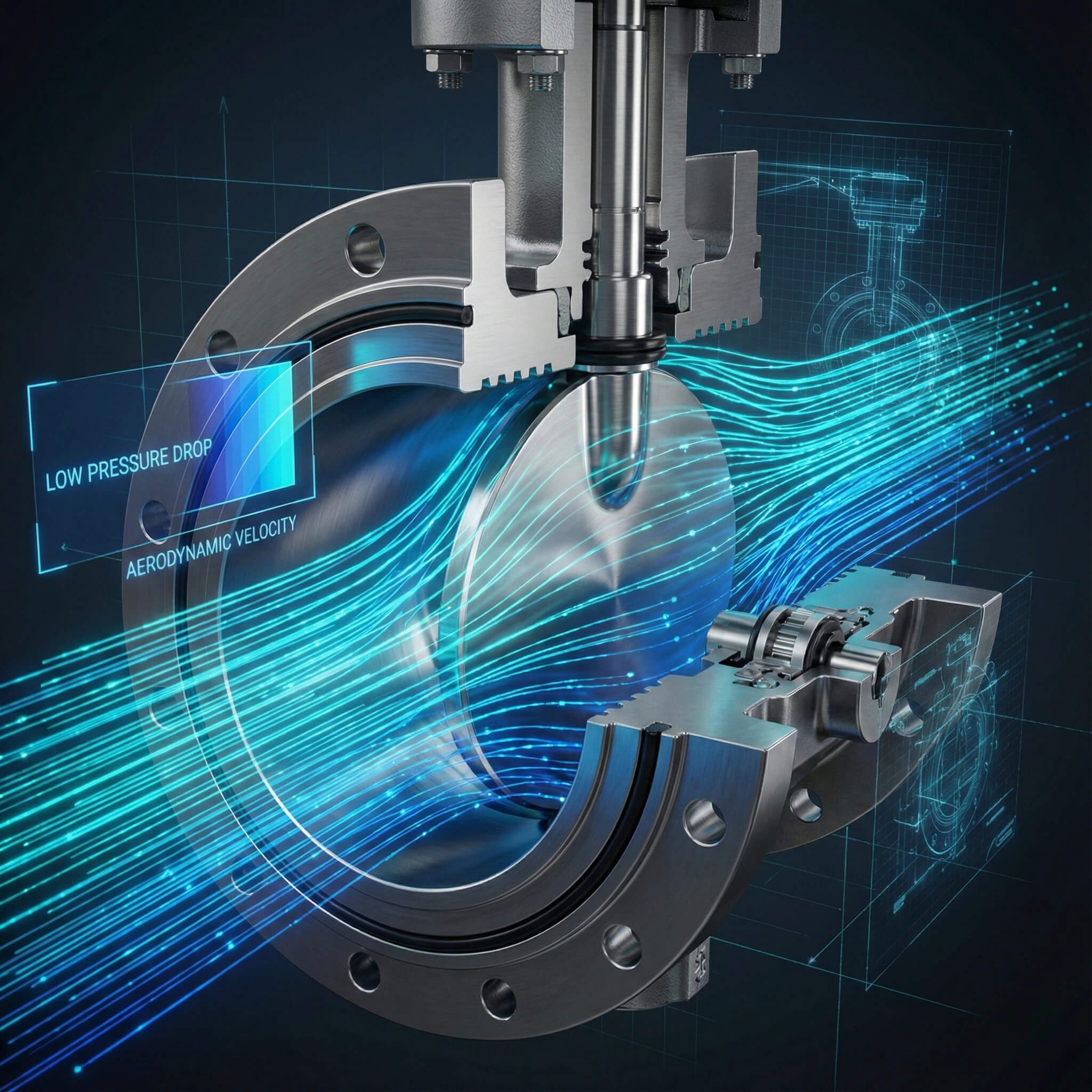
Managing industrial fluid systems effectively requires a deep understanding of flow dynamics, specifically regarding the pressure loss and flow resistance coefficient of pneumatic butterfly valves. Industrial pumping systems running continuously often bleed budget through hidden energy costs caused by high flow resistance, leading to pump fatigue and TCO destruction. RUITO’s valves, engineered with optimized disc geometry and verified by ANSYS simulation, provide the low pressure drop solution needed to stabilize system pressure and cut operational costs.
1. Causes of Butterfly Valve Pressure Loss
What creates flow resistance?
In any piping system, the valve disc acts as a necessary obstruction that creates physical drag even when fully open. The thickness of the disc and the profile of the shaft are primary contributors to this resistance, naturally displacing fluid. Thicker discs required for higher pressure ratings force media to accelerate around the obstruction, leading to a local pressure drop.
- Disc thickness creates physical obstruction
- Shaft profile disrupts fluid velocity
- Higher pressure ratings increase displacement
Does geometry impact pressure?
Here is the deal: The geometry of the valve body itself plays a massive role, as standard concentric designs place the shaft directly in the center of the flow stream. This design splits the fluid velocity profile, creating wake turbulence and eddies that consume kinetic energy without contributing to forward flow. Energy lost to this turbulence manifests directly as pressure loss across the valve.
- Concentric designs split velocity profiles
- Turbulence creates energy-sucking eddies
- Rough surface finishes increase friction
How to lower surface friction?
You might be wondering if material choice matters here, and RUITO addresses this through precision engineering and specific lining options. We offer PTFE lined options which provide a much lower surface friction coefficient than rough metal, directly lowering the drag force exerted on the fluid. By optimizing disc profile, shaft placement, and surface finish, we minimize the unavoidable resistance inherent in valve design.
- CNC machining ensures precise tolerances
- Automatic spraying creates smoother finishes
- PTFE linings reduce fluid drag force
| Factor | Impact on Loss | Solution |
|---|---|---|
| Disc Profile | High | Streamlined Geometry |
| Surface Finish | Medium | CNC & Spraying |
| Material | Medium | PTFE Lining |
Optimizing physical factors minimizes unavoidable resistance inherent in valve design.
Key Takeaway: Precision manufacturing and low-friction materials like PTFE are essential for minimizing drag and optimizing flow dynamics.
2. Calculating Butterfly Valve Pressure Loss
How do you measure efficiency?
Engineers rely heavily on the Flow Coefficient (Cv in imperial, Kv in metric) to quantify pressure loss and compare valve efficiency baselines. A higher Cv indicates lower resistance and higher flow capacity, while a low Cv suggests a restrictive valve. This metric serves as the standard baseline for comparing valve efficiency across different manufacturers.
- Cv measures flow in US gallons
- Kv serves as the metric standard
- Higher values indicate better flow
Is one value enough?
But here is the catch: relying on a single Cv value at 100% open is dangerous because pneumatic butterfly valves modulate flow. You must calculate pressure loss across the entire opening range using the formula $Q = Cv \times \sqrt{\Delta P / SG}$ to ensure accuracy. Converting Cv to Kv ($Kv = 0.86 \times Cv$) is also vital for ensuring compatibility with global specifications.
- Valves modulate across various angles
- Formula uses flow rate and gravity
- Convert Cv to Kv for DIN standards
Why use the Darcy-Weisbach equation?
We apply rigorous analysis methods that account for friction losses in the pipe network related to the valve’s resistance coefficient ($K$). RUITO generates detailed charts showing values at every 10 degrees of opening to empower your head loss predictions. This data empowers you to predict exactly how much head loss your pump must overcome at any operating point.
- Accounts for pipe network friction
- Uses dimensionless K-factor values
- Predicts head loss at operating points
| Coefficient | System | Application |
|---|---|---|
| Cv | Imperial | Oil & Gas |
| Kv | Metric | Municipal Water |
| K-Factor | Dimensionless | Network Analysis |
Accurate calculations require detailed data across the full opening range, not just a single static point.
Key Takeaway: Use comprehensive flow coefficients and opening-angle charts to accurately predict system pressure drops.
3. Comparing Butterfly Valve Pressure Loss
How do valve types compare?
Comparing these valves reveals they offer moderate pressure recovery compared to full-port ball or gate valves. Gate valves retract completely for near-zero drop, but butterfly valves trade a small amount of pressure loss for speed, compact size, and cost-effectiveness. This makes them the versatile choice for systems where space and speed are critical.
- Gate valves offer near-zero drop
- Ball valves provide full-port flow
- Butterfly valves balance size and speed
Are globe valves better?
What’s the real story? While they have higher loss than gate valves, high-performance butterfly valves significantly outperform globe valves. Globe valves force fluid to change direction twice creating massive drops, whereas the straight-through path of a butterfly valve is aerodynamically superior. The key variable determining efficiency remains the specific disc design.
- Globe valves force directional changes
- Straight paths improve aerodynamics
- Disc design dictates performance
Which design fits high flow?
This is where it gets interesting: For critical high-flow applications, we recommend eccentric designs that move the disc away from the seat immediately upon opening. In large diameter applications, even minor resistance reductions save kilowatts of pumping power, providing tight shutoff with superior flow characteristics. We position our valves as the optimal balance point between efficiency and cost.
- Eccentric designs reduce seat friction
- Streamlined profiles aid high flow
- Tight shutoff meets API 609 standards
| Valve Type | Pressure Loss | Cost/Size |
|---|---|---|
| Gate | Very Low | High/Bulky |
| Globe | Very High | Medium/Heavy |
| RUITO Butterfly | Low/Moderate | Low/Compact |
Eccentric butterfly valves offer the optimal balance of flow characteristics and operational efficiency for large systems.
Key Takeaway: High-performance eccentric designs significantly reduce energy consumption compared to standard globe or concentric valves.
4. Reducing Butterfly Valve Pressure Loss
Is your valve sized correctly?
Reducing pressure loss is often a matter of correct sizing rather than just changing valve types. A common mistake is “line-sizing” the valve, which causes velocity spikes and turbulence if the valve is undersized to save money. The goal is to size the valve so that the required flow rate occurs between 30° and 70° of opening.
- Line-sizing can create choke points
- Undersizing explodes system turbulence
- Optimal flow occurs at 30°-70°
Do materials reduce drag?
Ready for the good part? You can actively lower resistance by choosing RUITO’s PTFE lined butterfly valves. This hydrophobic material resists adhesion from viscous fluids, allowing media to slide over the surface with minimal drag and preventing port narrowing. A PTFE lined valve resists adhesion where metal discs might accumulate buildup.
- PTFE offers low friction coefficients
- Resists buildup from viscous slurries
- Prevents port narrowing over time
How does simulation help?
We utilize ANSYS fluid simulation to refine disc profiles by rounding edges and streamlining shaft connections. This engineering intervention prevents large turbulent eddies from forming and allows us to modify geometry for hyper-critical applications rapidly. Our factory-direct control allows us to implement these design tweaks to shave off resistance points.
- Rounding edges reduces wake zones
- Prevents energy-sucking turbulence
- Factory-direct mods refine geometry
| Strategy | Mechanism | Reduction Impact |
|---|---|---|
| Optimal Sizing | Matches Cv to Flow | High |
| PTFE Lining | Low Friction | Medium |
| Eccentric Design | Streamlined Path | High |
Combining correct sizing with advanced simulation and materials yields the lowest possible flow resistance.
Key Takeaway: Proper sizing and advanced materials like PTFE actively lower resistance and prevent costly turbulence.
5. Monitoring Butterfly Valve Pressure Loss
Why install pressure gauges?
You cannot manage what you do not measure, so installing pressure gauges upstream and downstream provides raw calculation data. In modern setups, differential pressure transmitters connected to SCADA systems monitor this crucial delta for diagnostics. A sudden spike usually indicates debris blockage, a slipped seat, or disc failure.
- Gauges provide raw $\Delta P$ data
- Connects to SCADA for monitoring
- Spikes indicate blockage or failure
Does data validate pumps?
But wait, there is more. Monitoring pressure loss validates your pump sequencing to ensure you are not operating off the best efficiency point (BEP). We provide flow curves that allow you to correlate your SCADA data with theoretical performance to immediately spot anomalies. Deviations from lab-certified Cv curves trigger immediate investigations.
- Validates pump efficiency points
- Correlates field data with lab curves
- Triggers investigations into anomalies
Can you predict maintenance?
Operators monitor pressure drop to determine maintenance intervals, as seal wear or cavitation damage changes flow characteristics. Trending the pressure loss coefficient allows you to predict seal failure before leaks occur based on RUITO’s stable valve performance. This strategy relies entirely on the predictable, stable performance of the valve.
- Trends predict seal failure risks
- Identifies cavitation damage early
- Relies on predictable valve stability
| Action | Benefit | Outcome |
|---|---|---|
| Real-time Monitoring | Diagnostics | Detect Blockages |
| Data Correlation | Efficiency | Validate Pump BEP |
| Trend Analysis | Maintenance | Predict Failures |
Continuous monitoring transforms pressure data into a predictive maintenance tool for long-term system health.
Key Takeaway: Real-time pressure monitoring allows for predictive maintenance and validation of pump efficiency.
6. Costs of Butterfly Valve Pressure Loss
How does loss affect TCO?
Ignoring pressure loss is a financial error because every psi lost must be compensated for by electricity. In continuous systems, the cumulative cost of wasted energy drives up head requirements, motor sizes, and monthly utility bills significantly. We frame this strictly as a Total Cost of Ownership (TCO) issue.
- Pressure loss increases electricity use
- Requires larger pumps and motors
- Destroys Total Cost of Ownership
Does cheap hardware pay off?
Let’s face it: Buying a cheaper valve with poor flow characteristics only saves you money on day one. High pressure loss creates velocities that breed cavitation, eating away at metal discs and destroying rubber seats through vibration. If a valve restricts flow efficiently, you pay for that “savings” every single hour the pump runs.
- Ongoing costs exceed initial savings
- High velocity breeds cavitation bubbles
- Vibration damages joints and seats
What is the ROI?
RUITO positions our valves as a TCO-friendly choice where precision CNC machining leads to lower energy bills. We provide the data necessary for you to calculate the ROI of upgrading, proving the purchase price is a fraction of the true cost. By investing in verified low resistance coefficients, you protect your pumps from backpressure fatigue.
- Smoother paths reduce energy bills
- Protects pumps from backpressure
- Proven ROI via efficiency data
| Factor | High Loss Consequence | Cost Impact |
|---|---|---|
| Energy | Pump Overwork | Operational |
| Cavitation | Physical Damage | Replacement |
| Vibration | Loose Joints | Maintenance |
Investing in efficient valves reduces long-term operational costs and protects equipment from physical damage.
Key Takeaway: High pressure loss drives up TCO through energy waste and equipment damage; efficient valves offer rapid ROI.
7. Predicting Butterfly Valve Pressure Loss
How does CFD work?
Predicting pressure loss before procurement is essential, so we rely on computational fluid dynamics to model complex interactions. RUITO employs advanced software like ANSYS to input fluid properties and run scenarios across the entire range of opening angles. This generates a predictive pressure map showing exactly where high-velocity zones occur.
- Models complex fluid interactions
- Uses ANSYS and SolidWorks
- Maps high-velocity zones
Does viscosity matter?
This is critical: Viscosity changes everything, as high-viscosity fluids experience much higher shear stress passing the disc. Our engineering team applies correction factors to standard Cv values to account for Reynolds number transitions from turbulent to laminar. Standard equations no longer apply when flow transitions due to high viscosity.
- Viscosity alters shear stress
- Correction factors adjust Cv values
- Accounts for laminar transitions
Can we simulate systems?
We provide predictive insights to simulate performance within your specific piping geometry, helping you avoid flow distortion. This level of predictive engineering distinguishes RUITO by selling guaranteed fluid performance based on rigorous mathematical modeling. We can predict if placing an elbow too close will distort the flow profile.
- Simulates specific pipe geometry
- Predicts elbow flow distortion
- Guarantees performance via math
| Variable | Simulation Input | Result |
|---|---|---|
| Geometry | Pipe Layout | Flow Profile |
| Fluid | Viscosity/Density | Shear Stress |
| Operation | Opening Angle | Pressure Map |
Advanced simulation ensures valve performance matches specific system requirements before physical installation.
Key Takeaway: CFD modeling and viscosity corrections ensure accurate pressure loss predictions for specific system geometries.
8. Testing Butterfly Valve Pressure Loss
Is simulation enough?
Simulation is theory, but testing is reality, so RUITO operates a comprehensive hydrostatic testing facility to validate claims. We perform type testing in a calibrated flow loop equipped with high-precision differential pressure transducers and magnetic flow meters. Every batch of valves undergoes rigorous testing beyond routine shell integrity checks.
- Hydrostatic facility validates theory
- Calibrated loops measure flow
- Precision transducers record data
How do we verify Cv?
Here is the bottom line: We measure actual pressure drop at various flow rates to construct the Cv curves published in our catalogs. This validation ensures theoretical values from ANSYS simulations match the physical reality of the cast iron product. It is crucial for skeptical buyers who demand proof.
- Measures actual drop at flow rates
- Constructs empirical Cv curves
- Matches simulation to reality
Who verifies the tests?
We are open to third-party validation and frequently host inspectors from agencies like SGS or TUV to witness these tests. This commitment ensures that when you install a RUITO valve, the pressure drop on your gauge matches our datasheet. We verify that massive designs maintain structural rigidity without deforming.
- Hosts SGS and TUV inspectors
- Verifies structural rigidity
- Guarantees datasheet accuracy
| Test Type | Purpose | Standard |
|---|---|---|
| Hydrostatic | Shell Integrity | API 598 |
| Flow Loop | Verify Cv/Kv | Empirical |
| Third-Party | Witness/Audit | SGS/TUV |
Physical testing and third-party validation provide the empirical proof needed to trust theoretical performance data.
Key Takeaway: Rigorous empirical testing and third-party validation guarantee that real-world performance matches technical specifications.
9. Future of Butterfly Valve Pressure Loss
Will materials change?
The future focuses on maximizing efficiency through smart materials that offer the strength of metal with surface slickness. These composites allow for thinner disc profiles that withstand high pressures while occupying less volume in the flow path. Less volume means less obstruction and lower pressure loss.
- Composites offer metal strength
- Thinner profiles reduce volume
- Slick surfaces lower friction
Can valves self-diagnose?
Think about this: Smart valves are the next frontier, integrating pressure sensors directly into the body for real-time self-diagnostics. If the pressure drop coefficient rises, the valve signals the central controller regarding cleaning needs or seat swelling. RUITO is actively researching these integrations to support Industry 4.0.
- Sensors integrated into body
- Reports coefficients in real-time
- Signals maintenance needs
Are offsets evolving?
We are refining eccentric designs to make triple-offset valves more affordable and compact through improved manufacturing. RUITO remains at the forefront, upgrading CNC equipment to make low-friction benefits accessible for standard water applications. We are constantly delivering the most efficient flow control solutions on the market.
- Triple-offsets becoming compact
- Tighter tolerances reduce cost
- Accessible for standard water
| Innovation | Benefit | Application |
|---|---|---|
| Composites | Thinner Discs | High Pressure |
| Smart Sensors | Self-Diagnostics | Industry 4.0 |
| Advanced CNC | Affordable Offsets | Standard Water |
Technological advancements in materials and smart integration are driving the next generation of efficient flow control.
Key Takeaway: Emerging smart technologies and material sciences are making high-efficiency valves smarter and more accessible.
Conclusion
Unchecked pressure loss acts as a silent brake on your system, driving up energy costs and risking equipment failure. It is not merely a technical specification; it is a direct drain on your profitability. RUITO positions itself as your strategic partner in eliminating this waste by providing valves optimized for minimal flow resistance and maximum reliability (DN25-DN3000, PN25).
With 20 years of expertise, factory-direct control, and a team of fluid mechanics experts, we combine advanced ANSYS simulation with rigorous physical testing to ensure our Cv data is accurate. Whether you need a standard wafer valve or a custom PTFE-lined solution, we have the engineering depth to support your project. Stop guessing at flow dynamics and partner with a manufacturer that validates performance through data. Contact RUITO today to secure your system’s efficiency and longevity.
FAQ
Can I calculate pressure drop accurately without software?
Yes, you can calculate it using the basic formula $\Delta P = SG \times (Q / Cv)^2$ if you have the manufacturer’s Cv value, but software is better for complex systems.
What’s the best valve design to minimize pressure loss?
Eccentric (offset) designs are best because they reduce seal friction and offer a more streamlined flow path compared to concentric rubber-lined valves.
How do I know if high pressure loss is damaging my system?
Look for symptoms like cavitation noise, vibration in the piping, premature seal failure, or pumps operating far outside their best efficiency point.
Can I reduce pressure loss by changing materials?
Yes, using low-friction materials like PTFE linings prevents buildup and reduces surface drag, which actively lowers the pressure drop across the valve.
What’s the best way to monitor performance?
Install differential pressure transmitters upstream and downstream to feed real-time data into your SCADA system for continuous efficiency tracking.