

Butterfly valve torque standards and testing methods involve specific engineering protocols to calculate the rotational force needed for tight shutoff across various industrial applications. These methods ensure that operators select actuators with enough power to overcome internal friction and line pressure without over-engineering the system. By utilizing precise formulas and safety factors, facilities can guarantee operational longevity and prevent mechanical failure.
How to perform butterfly valve torque calculation?
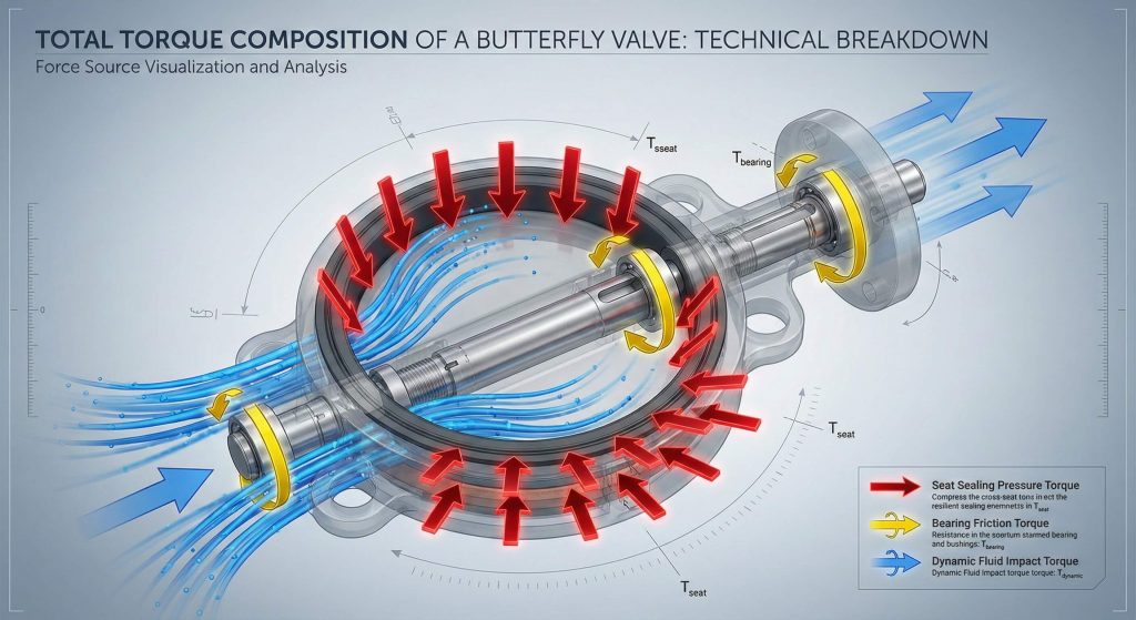
You perform a butterfly valve torque calculation by summing the required forces for seating, bearing friction, and dynamic fluid resistance. This total value is measured in Newton-meters and serves as the baseline for actuator sizing.
Integrating the primary force components
But here is the kicker: the calculation must account for the specific friction coefficients of the disc and seat materials used in the assembly.
- Seating torque required to compress the elastomer.
- Bearing torque caused by shaft friction.
- Dynamic torque from fluid velocity.
Key Takeaway: Combining all internal friction points is the only way to determine the minimum operational force required.
| Force Type | Impact on Total Torque | Calculation Variable |
|---|---|---|
| Seating | High | Seat Friction Coefficient |
| Bearing | Moderate | Shaft Diameter |
| Dynamic | Variable | Fluid Velocity |
Determining each component separately allows engineers to pinpoint where the most resistance occurs in the cycle.
Why is butterfly valve torque calculation necessary?
A butterfly valve torque calculation is necessary to ensure the chosen actuator can move the disc under the most demanding system conditions. Without this data, you risk installing underpowered hardware that fails to close during high-pressure surges.
Preventing critical system failures
Think about it: an incorrectly sized actuator can lead to sheared stems or burnt-out electric motors during routine operations.
- Ensures consistent bubble-tight sealing.
- Protects the valve stem from twisting.
- Optimizes pneumatic air consumption.
Key Takeaway: Accurate data serves as an insurance policy against mechanical fatigue and operational downtime.
| Risk Factor | Consequence | Mitigation Strategy |
|---|---|---|
| Under-Sizing | Incomplete closure | Precise calculation |
| Over-Sizing | Mechanical stress | Optimal hardware selection |
| Friction | Seat wear | Lubrication and testing |
Establishing torque requirements during the design phase eliminates expensive field modifications later in the project.
How do standards influence butterfly valve torque calculation?
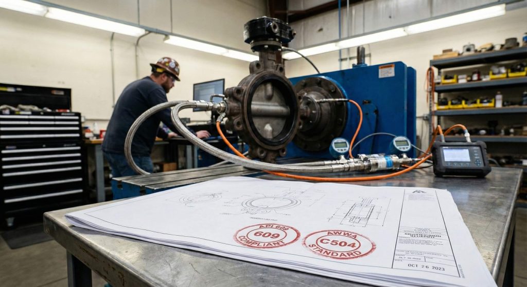
Industrial standards like API 609 and AWWA C504 influence your butterfly valve torque calculation by defining the testing parameters for safety and reliability. These regulations mandate specific pressure differentials that must be used during the verification process.
Adhering to global engineering benchmarks
The best part? Following these standards ensures that your equipment is compatible with international safety and quality requirements.
- API 609 for heavy industrial use.
- AWWA C504 for municipal water systems.
- ISO 5211 for actuator mounting.
Key Takeaway: Compliance with recognized standards provides a repeatable framework for measuring valve performance.
| Standard | Primary Focus | Industry Application |
|---|---|---|
| API 609 | Sealing Integrity | Oil and Gas |
| AWWA C504 | Cycle Longevity | Water Works |
| ISO 5211 | Interface Specs | Automation |
Regulatory compliance ensures that the torque values provided on data sheets are accurate and trustworthy.
Where does friction affect butterfly valve torque calculation?
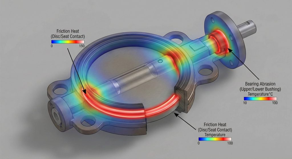
Friction primarily affects your butterfly valve torque calculation at the contact point between the disc edge and the resilient seat liner. Secondary friction occurs within the stem bearings as line pressure pushes the shaft against the bushings.
Mapping the mechanical resistance points
It gets better: understanding these specific points of contact allows for better maintenance and lubrication strategies to reduce wear.
- Disc and seat interference zone.
- Stem packing and seal contact.
- Upper and lower bearing surfaces.
Key Takeaway: Identifying friction zones helps engineers select materials that minimize energy requirements while maintaining a seal.
| Friction Zone | Intensity | Mitigation |
|---|---|---|
| Seat Area | High | Material selection |
| Stem Packing | Low | Proper tensioning |
| Bearing | Medium | High-quality bushings |
Minimizing friction at these critical interfaces extends the service life of the entire valve assembly.
How can flow impact your butterfly valve torque calculation?
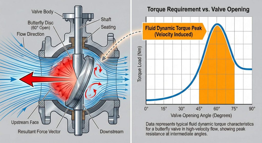
High fluid velocity directly impacts your butterfly valve torque calculation by creating dynamic forces that push against the disc as it opens. This force, known as dynamic torque, can actually assist or hinder the movement depending on the flow direction.
Managing dynamic fluid forces
Why does this matter? In high-flow systems, dynamic torque can exceed the force required to break the seat seal.
- High velocity increases dynamic resistance.
- Fluid density changes the load on the disc.
- Flow direction affects the holding torque.
Key Takeaway: Dynamic forces must be included in any system where fluid velocity exceeds six meters per second.
| Flow Condition | Torque Impact | Design Focus |
|---|---|---|
| Low Velocity | Minimal | Seat Friction |
| High Velocity | Significant | Dynamic Load |
| Slurry Flow | Very High | Mechanical Obstruction |
Accounting for fluid dynamics ensures the valve remains stable even during peak flow events.
What tools assist in butterfly valve torque calculation?
Various tools assist in a butterfly valve torque calculation, ranging from manual torque wrenches for field checks to electronic sensors for lab testing. These devices provide the physical data needed to verify that the mathematical models are correct.
Verifying data with precision instruments
Here is the deal: using calibrated tools ensures that the measurements taken during commissioning are accurate and repeatable.
- Calibrated manual torque wrenches.
- Electronic strain gauge sensors.
- Hydraulic testing rigs for high pressure.
Key Takeaway: Verification tools bridge the gap between theoretical math and actual mechanical performance.
| Tool Type | Accuracy Level | Best Use Case |
|---|---|---|
| Torque Wrench | Moderate | Field Maintenance |
| Electronic Sensor | High | Product Development |
| Hydraulic Rig | High | Pressure Validation |
Consistent use of testing tools ensures that every valve meets its specified performance curve before installation.
How do seat materials alter butterfly valve torque calculation?
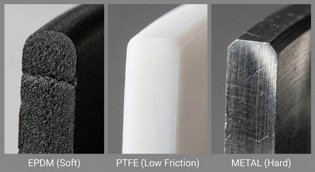
Seat materials alter the butterfly valve torque calculation because different polymers have varying coefficients of friction and stiffness. For example, a PTFE seat requires much higher force to achieve a seal than a soft EPDM rubber seat.
Selecting the right sealing material
You might be wondering: does a harder material always mean a better seal? While harder materials handle chemicals better, they significantly increase the required actuator power.
- EPDM offers low friction for water.
- PTFE requires high force for chemicals.
- Metal seats demand the highest torque output.
Key Takeaway: Material properties are the single largest variable in determining the static friction of the valve.
| Material | Friction Level | Energy Demand |
|---|---|---|
| EPDM Rubber | Low | Low |
| PTFE Polymer | High | High |
| Metal Alloy | Very High | Extreme |
Choosing the correct seat material balances chemical compatibility with the energy efficiency of the actuation system.
When should you re-verify butterfly valve torque calculation?
You should re-verify a butterfly valve torque calculation during annual maintenance cycles to account for material hardening or corrosion. Over time, environmental factors can increase the force required to move the disc from its seated position.
Maintaining long term operational health
Wait, there’s more: regular verification allows you to detect early signs of bearing failure before they cause a total system shutdown.
- After long periods of inactivity.
- Following a major pressure surge event.
- During scheduled annual safety inspections.
Key Takeaway: Periodic testing ensures that the safety factors applied during design remain valid over time.
| Timing | Activity | Goal |
|---|---|---|
| Commissioning | Initial verification | Baseline data |
| Annual Check | Torque measurement | Trend analysis |
| Post-Repair | Full cycle test | Component validation |
Routine re-verification protects your infrastructure from the unpredictable effects of aging and chemical exposure.
How to apply safety in butterfly valve torque calculation?
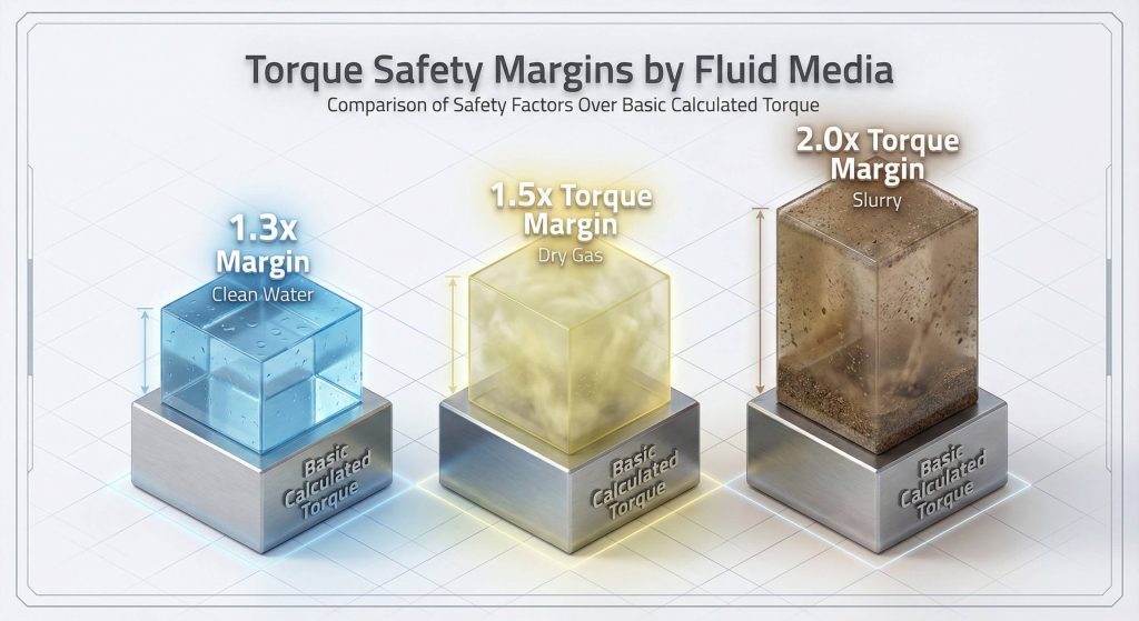
You apply safety in a butterfly valve torque calculation by adding a minimum 30% multiplier to your final result. This buffer accounts for the “stiction” that occurs when a valve remains closed for long periods in a pressurized line.
Incorporating engineering safety margins
Ready for the good part? This safety factor ensures that your system will still operate even if the seat hardens or debris enters the line.
- 1.3x multiplier for clean water.
- 1.5x multiplier for dry gas.
- 2.0x multiplier for abrasive slurries.
Key Takeaway: Never select an actuator that matches your calculated torque exactly; always include a safety margin.
| Service Medium | Safety Factor | Reason |
|---|---|---|
| Wet (Lubricated) | 1.3 | Standard buffer |
| Dry (Non-lubricated) | 1.5 | Increased friction |
| Slurry (Abrasive) | 2.0 | Blockage risk |
Applying a robust safety factor is the most effective way to guarantee reliability in real-world operating conditions.
How does automation help butterfly valve torque calculation?
Automation helps your butterfly valve torque calculation by providing real-time feedback on the actual force being used during every cycle. Smart actuators can log this data to create a performance history that alerts you to changes in mechanical health.
Utilizing smart control systems
What’s the real story? Automation transforms a static calculation into a dynamic monitoring tool that prevents unplanned downtime.
- Detects early signs of seat wear.
- Monitors motor current to infer load.
- Provides remote diagnostic reporting.
Key Takeaway: Automated feedback loops allow for predictive maintenance based on actual torque trends rather than guesswork.
| Automation Feature | Benefit | Result |
|---|---|---|
| Data Logging | Performance tracking | Predictive repairs |
| Current Monitoring | Real-time load check | Motor protection |
| Remote Alerts | Faster response time | Reduced downtime |
Integrating torque data into your central control system provides a birds-eye view of your facility’s mechanical integrity.
Summary and Conclusion
Mastering butterfly valve torque standards and testing methods is critical for the safety and efficiency of any fluid control system. By combining technical formulas with industry-standard safety margins, engineers can ensure reliable operation under the most extreme conditions. Our vision is to lead the industry by providing precision-engineered solutions that prioritize mechanical integrity and long-term value. If you require a detailed torque analysis for your specific project, please contact us today for expert consultation.
FAQ
How do I calculate torque for a dry gas system?
You must apply a 1.5x safety factor to the base calculation because dry gas provides no lubrication for the seat.
Why is breakaway torque higher than running torque?
Breakaway torque must overcome the static friction and compression of the seat, which is always higher than the kinetic friction of motion.
Can seat material double the required torque?
Yes, switching from a soft EPDM to a hard PTFE or metal seat can easily double the rotational force required.
How often should torque values be checked in the field?
We recommend checking torque values during every annual maintenance cycle to monitor for seat hardening or corrosion.
What happens if I use an undersized actuator?
An undersized actuator will likely fail to close the valve against full line pressure, leading to persistent leaks and motor damage.