
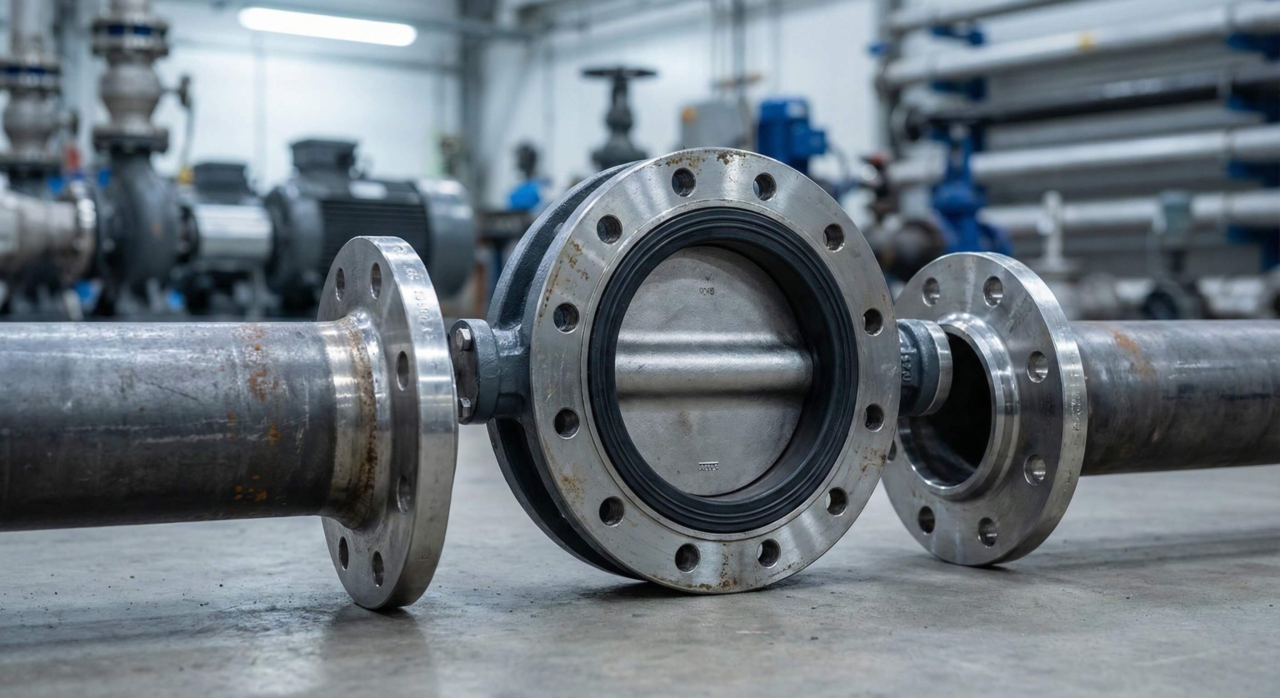
Selecting the wrong butterfly valve flange dimensions for your pipeline leads to catastrophic seal failures and expensive emergency shutdowns. You face mounting pressure when mismatched bolt holes halt a multi-million dollar installation and compromise site safety. Here is the deal: our complete guide provides the technical roadmap you need for perfect alignment. By mastering these specifications, you eliminate procurement risks and ensure a seamless integration for your high-pressure fluid control systems.
What are standard butterfly valve flange dimensions?
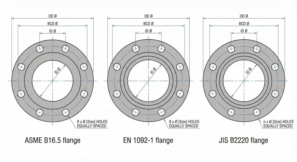
Butterfly valve flange dimensions follow strict international standards to ensure hardware compatibility across global supply chains. These metrics define the outer diameter, metal thickness, and bolt circle patterns necessary for a secure mechanical joint. You typically rely on ASME B16.5 for imperial systems or EN 1092-1 for metric projects. Understanding these universal rules allows you to source components with total confidence from any reputable manufacturer.
Why do standards matter for your project?
Think about it, without universal standards, every piping project would require expensive custom-machined adapters.
- ASME B16.5 governs North American oil and gas lines.
- EN 1092-1 serves European water treatment facilities.
- JIS B2220 remains the standard for Asian marine industries.
How does nominal diameter affect sizing?
Here is the deal, the nominal diameter acts as your primary reference for locating detailed sizing tables.
- DN50 aligns with 2-inch industrial piping.
- DN200 corresponds to 8-inch high-flow systems.
- DN600 represents large-scale 24-inch municipal mains.
Key Takeaway: Adherence to international standards is the only way to guarantee mechanical fitment and prevent installation delays.
The following table summarizes the primary standards used to define dimensions across different global regions.
| Standard System | Common Region | Primary Units | Typical Application |
|---|---|---|---|
| ASME B16.5 | North America | Imperial (Inches) | Oil, Gas, and Heavy Industry |
| EN 1092-1 | Europe / Global | Metric (Millimeters) | Water Treatment and Utilities |
| JIS B2220 | Asia / Marine | Metric (Millimeters) | Shipbuilding and Offshore |
Use this data to confirm which regulatory body governs your current infrastructure requirements.
How to measure butterfly valve flange dimensions?
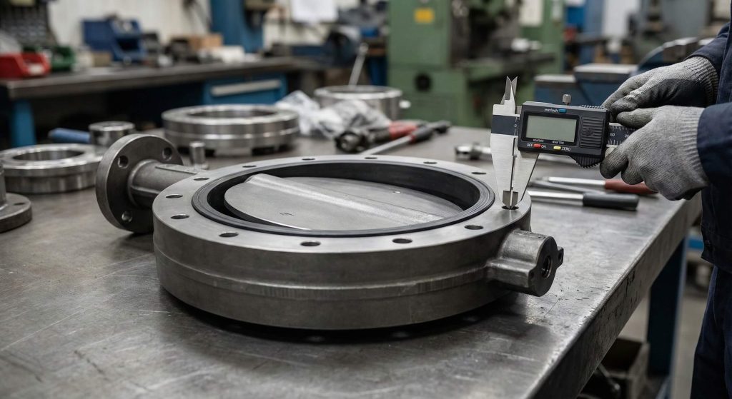
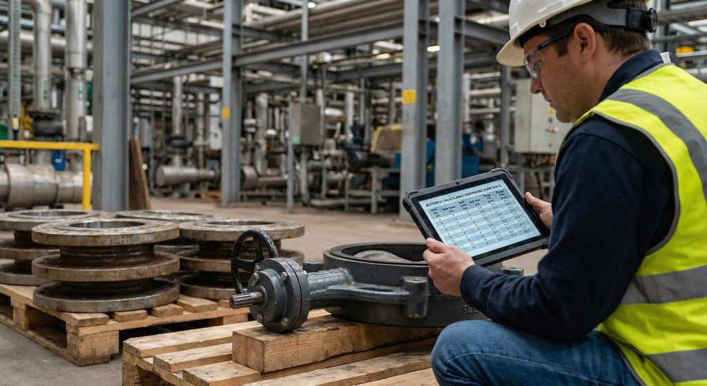
Measuring butterfly valve flange dimensions correctly requires precision tools like digital calipers to avoid procurement errors. You must identify the bolt circle diameter (BCD) by measuring from the center of one hole to the center of the opposite hole. Accuracy in this phase is strictly necessary because a minor deviation prevents bolts from passing through the assembly. You should also record the face-to-face length to confirm the valve fits the physical gap in your pipeline.
How to identify the bolt circle diameter?
But wait, there is more to measuring BCD than just a quick glance at the flange face.
- Measure from the exact center of opposing bolt holes.
- Verify the symmetry across both the horizontal and vertical axes.
- Record the data in millimeters to match most manufacturer charts.
Why is face-to-face length critical?
Look: if your face-to-face measurement is off by even a few millimeters, the valve simply won’t fit between the pipes.
- Standardized by API 609 for most industrial models.
- Determines the total space required for the valve body.
- Affects the choice of through-bolts for wafer-style installations.
Key Takeaway: Precise field measurements of BCD and face-to-face length are essential for verifying component compatibility before purchase.
This table provides the essential tools required to capture accurate field data for your procurement team.
| Measurement Parameter | Tool Required | Criticality | Purpose |
|---|---|---|---|
| Bolt Circle Diameter | Digital Caliper | High | Ensures bolt alignment |
| Face-to-Face | Tape Measure | Medium | Confirms installation space |
| Flange Thickness | Micrometer | High | Verifies pressure rating |
Follow these steps to generate a reliable technical report for your valve supplier.
Why do butterfly valve flange dimensions vary by type?
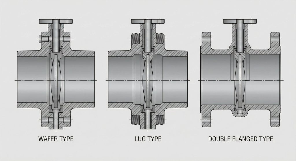
Butterfly valve flange dimensions vary significantly between wafer, lug, and flanged body styles due to their unique structural roles. Wafer styles feature a slim profile designed to be sandwiched between pipe flanges with long through-bolts. Lug styles include integrated metal “ears” with threaded holes for independent mounting to one side of the pipe. You must select the body type that aligns with your specific maintenance and safety requirements.
How does wafer style impact your footprint?
This is where it gets interesting, as the wafer design focuses entirely on space efficiency and weight reduction.
- Requires long bolts that span the entire valve width.
- Saves physical space in crowded piping layouts.
- Simplifies the alignment process during the initial installation phase.
What makes the lug style footprint different?
The best part is that the lug design allows for downstream piping removal while the system is pressurized.
- Features threaded inserts for secure, independent bolting.
- Heavier construction provides increased structural durability.
- Ideal for end-of-line service where safety is a priority.
Key Takeaway: Body style choice dictates the final external dimensions and the specific bolting hardware required for your project.
Compare the physical characteristics of common valve body styles using the summary table below.
| Valve Type | Body Width | Mounting Method | Primary Benefit |
|---|---|---|---|
| Wafer | Narrow | Sandwiched | Compact and lightweight |
| Lug | Medium | Bolted to each flange | Facilitates maintenance |
| Double Flanged | Wide | Direct pipe bolting | Best for large diameters |
Assess your system’s accessibility needs to determine the most appropriate valve body configuration.
Are butterfly valve flange dimensions same globally?

Are butterfly valve flange dimensions consistent across different regions, or do you need to worry about imperial versus metric mismatches? The reality is that ANSI and DIN patterns rarely align, even if the nominal pipe size appears identical to the naked eye. You cannot bolt an ANSI Class 150 valve to a PN16 pipe without using a specialized transition flange. Mixing these standards leads to structural weaknesses and immediate leakage at the joint.
Why does the ANSI vs DIN mismatch occur?
Believe it or not, the mathematical formulas for hole placement differ between US and European engineering traditions.
- ANSI B16.5 utilizes imperial spacing for bolt patterns.
- DIN/EN standards utilize metric measurements for BCD.
- Hole counts can vary even when the diameter is similar.
How do you manage multi-standard projects?
Ready for the good part? Many manufacturers now offer multi-standard valves with slotted bolt holes.
- Slotted holes accommodate both ANSI and DIN patterns.
- Simplifies inventory management for global contractors.
- Always verify that the pressure rating meets both standards.
Key Takeaway: Never assume imperial and metric valves are interchangeable without verifying the specific bolt circle diameter.
The following data highlights the BCD discrepancies between the most common international standards.
| Nominal Size | ANSI Class 150 BCD | PN16 (DIN) BCD | Alignment Result |
|---|---|---|---|
| 2″ (DN50) | 120.7 mm | 125.0 mm | Connection Failure |
| 4″ (DN100) | 190.5 mm | 180.0 mm | Connection Failure |
| 8″ (DN200) | 298.5 mm | 295.0 mm | Connection Failure |
Review your existing pipe certifications to avoid ordering incompatible hardware for your facility.
How do pressure ratings affect butterfly valve flange dimensions?
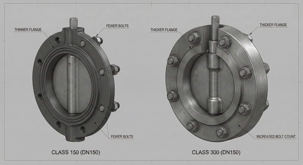
Butterfly valve flange dimensions increase dramatically as you move to higher pressure classes to maintain structural integrity under load. A Class 300 flange is significantly thicker and features larger bolt holes than a Class 150 equivalent for the same pipe size. This extra metal prevents the flange from warping or bowing under extreme internal force. You must carefully match your valve’s pressure rating to the maximum potential stress of your pump system.
Why does flange thickness increase?
Think about it, higher pressures require more metal to resist the clamping force of high-tension bolts.
- Prevents metal fatigue over long-term operation.
- Ensures even distribution of pressure across the gasket face.
- Determined by API and ASME safety calculations.
How does pressure impact the bolt count?
But here is the kicker, more bolts are needed to provide a uniform seal around the entire circumference.
- Class 150 may use 8 bolts for a 6-inch pipe.
- Class 300 may use 12 bolts for the same 6-inch line.
- Increased bolt counts require larger flange diameters for clearance.
Key Takeaway: Higher pressure requirements lead to beefier flanges and larger hardware to ensure the safety of the pressurized system.
This table illustrates how pressure class impacts the physical footprint of industrial butterfly valves.
| Pressure Class | Flange Thickness (6″) | Bolt Hole Count | Max Pressure (Bar) |
|---|---|---|---|
| Class 150 | 23.9 mm | 8 Holes | 19.6 Bar |
| Class 300 | 35.1 mm | 12 Holes | 51.1 Bar |
| PN16 | 24.0 mm | 8 Holes | 16.0 Bar |
Check your system’s maximum operating pressure to select the correct flange thickness for your application.
Can material choice change butterfly valve flange dimensions?
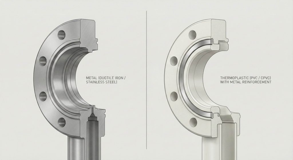
Can butterfly valve flange dimensions vary when you switch from ductile iron to a thermoplastic like PVC or CPVC? Plastic valves often feature wider flange faces to distribute mechanical stress effectively without cracking the polymer material. While metal valves follow rigid ASME or DIN standards, plastic equivalents often require metal reinforcement rings for safe bolting. You must account for these material differences during the structural design of your pipe supports.
Why do plastic valves need extra thickness?
But here is the kicker, polymers do not possess the same tensile strength as stainless steel or iron.
- Thicker flanges prevent cracking during the tightening process.
- Wider faces provide more surface area for the gasket seal.
- Reinforcement rings help distribute the bolt load evenly.
How do metal alloys impact your sizing?
The best part is that high-strength alloys like 316 stainless steel allow for more compact valve designs.
- Higher strength-to-weight ratio than standard cast iron.
- Allows for thinner flange profiles in non-standard applications.
- Maintains dimensional stability in highly corrosive environments.
Key Takeaway: Material selection influences the final flange profile and the specific torque requirements needed for a safe installation.
Review the material properties in the table below to understand their impact on valve dimensions.
| Material Type | Tensile Strength | Flange Profile | Best Use Case |
|---|---|---|---|
| Ductile Iron | High | Standard | Water and HVAC |
| 316 Stainless | Very High | Slim / Standard | Chemical Processing |
| PVC / CPVC | Low | Extra Thick | Low-Pressure Corrosives |
Select the material that balances chemical compatibility with the structural needs of your piping system.
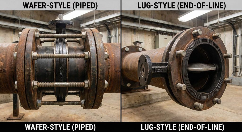
Butterfly valve flange dimensions are generally identical in terms of face-to-face length, but their bolting configurations differ fundamentally. Wafer valves rely on the centering of the body between two flanges, while lug valves use threaded holes to create a fixed connection. You must verify the thread pitch of the lug holes to ensure your bolts are compatible with the valve body. This distinction is vital for planning maintenance procedures that require pipe sections to be disconnected.
What defines the wafer style fitment?
This is where it gets interesting, as the wafer style depends entirely on external bolt tension for its seal.
- Features non-threaded guide holes for centering.
- Requires fewer bolts than a comparable lug-style valve.
- Offers the most compact face-to-face dimension for tight spaces.
Why choose the lug style connection?
The best part is that the lug design provides a higher level of versatility for system modifications.
- Allows for the removal of downstream piping under pressure.
- Threaded lugs act as a permanent part of the flange assembly.
- Provides a more secure mounting point for high-vibration lines.
Key Takeaway: While wafer and lug valves often share basic dimensions, their installation versatility and hardware requirements are totally different.
Use the comparison table below to decide which body style fits your mechanical and operational needs.
| Feature | Wafer Style | Lug Style | Selection Criteria |
|---|---|---|---|
| Threaded Holes | No | Yes | Maintenance Flexibility |
| Weight | Low | High | Support Requirements |
| End-of-Line | Not Recommended | Suitable | System Location |
Evaluate your long-term maintenance strategy before finalizing your choice between wafer and lug bodies.
How to verify butterfly valve flange dimensions for install?
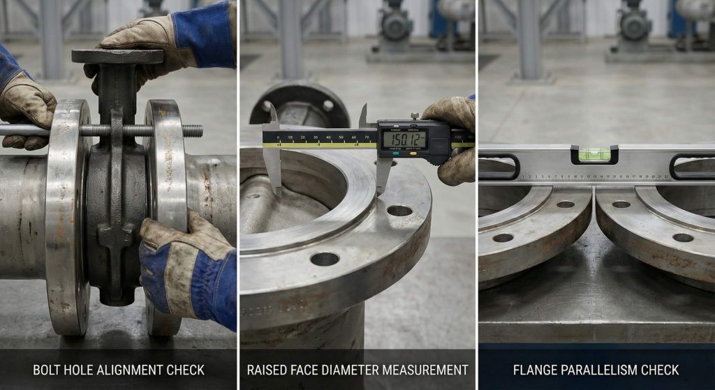
Verifying butterfly valve flange dimensions onsite is your final line of defense against costly installation errors or manufacturing defects. You should perform a physical check of the bolt hole alignment and the raised face diameter before lifting the valve into position. Using a pilot bolt to check every hole ensures that the flange will mate perfectly with the existing piping. You must also check the parallelism of the pipe flanges to avoid applying uneven stress to the valve body.
What is the pilot bolt test?
Think about it, a single misaligned hole can halt an entire project and force expensive field modifications.
- Slide a bolt through every hole to check for interference.
- Confirm that the bolt length is correct for the flange thickness.
- Verify that the valve is perfectly centered in the pipeline.
Why check the raised face diameter?
Look: if the raised faces of the valve and pipe don’t match, you will never achieve a high-pressure seal.
- The raised face concentrates clamping force on the gasket.
- Diameters must match within 1.0mm for a safe connection.
- Prevents the gasket from shifting during the tightening sequence.
Key Takeaway: Onsite verification prevents mechanical binding and ensures that your pressurized seal is reliable from day one.
This checklist provides the success metrics for your pre-installation dimension verification.
| Checkpoint | Action | Success Metric |
|---|---|---|
| Hole Alignment | Pilot Bolt Test | Smooth Bolt Entry |
| Raised Face | Caliper Measurement | Identical Diameters |
| Parallelism | Level Check | Within 0.5 Degrees |
Conduct these checks during the staging phase to eliminate the risk of late-stage installation failures.
Where to find charts for butterfly valve flange dimensions?
Butterfly valve flange dimensions charts are most easily found in official manufacturer datasheets or international standard publications. You should bookmark the technical resource pages of your preferred suppliers to ensure you always have access to the most current sizing data. Most charts list the nominal diameter, the number of bolt holes, the bolt size, and the flange thickness for every pressure class. Digital PDF catalogs allow you to verify specifications on your tablet while standing on the job site.
Why trust manufacturer datasheets over generic tables?
Here is the deal, while international standards provide a baseline, manufacturers often include extra metal for safety.
- Provides “as-built” dimensions for the specific model you purchased.
- Includes detailed drawings of the actuator mounting pad.
- Lists the exact torque values needed for a leak-free seal.
How do online sizing tools assist you?
But wait, there is more to these digital tools than just simple dimension lookups.
- Convert instantly between imperial and metric standards.
- Generate 3D CAD models for your engineering design team.
- Provide flow coefficient (Cv) data for pressure drop calculations.
Key Takeaway: Combining official manufacturer data with digital calculators provides the most accurate roadmap for your procurement process.
The table below lists the most reliable digital resources for accessing valve dimension data.
| Resource Type | Best Use Case | Update Frequency | Accuracy |
|---|---|---|---|
| Manufacturer PDF | Final Procurement | Occasional | Extremely High |
| Online Calculator | Preliminary Sizing | Continuous | High |
| Standards Book | System Design | 5-10 Years | Absolute |
Always verify your findings against the physical product’s technical plate once it arrives at your facility.
What impacts butterfly valve flange dimensions in high-heat?
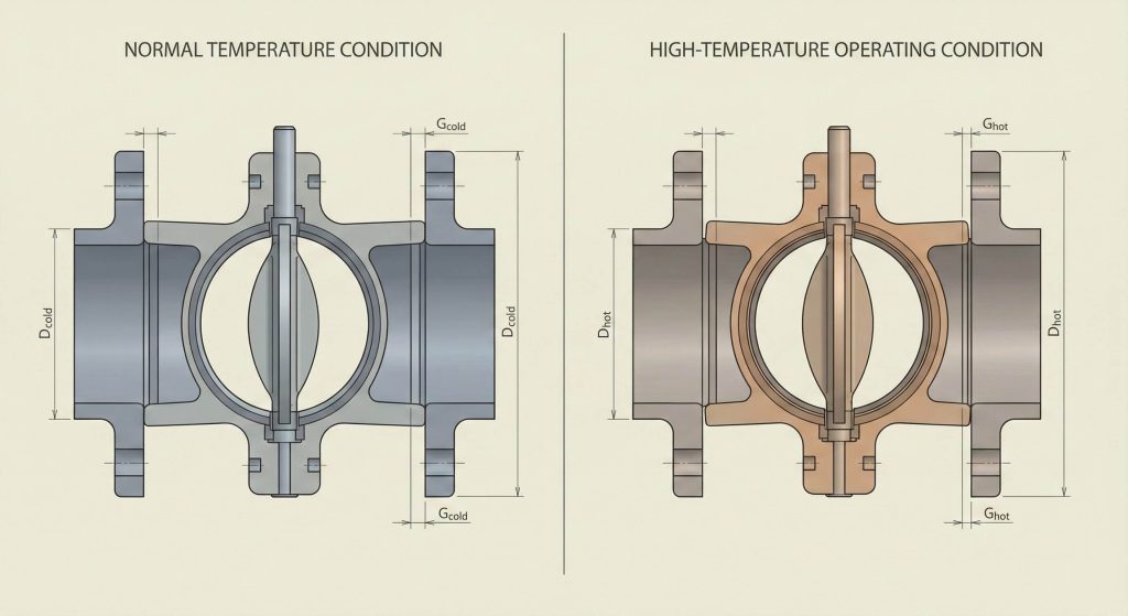
High-temperature applications alter butterfly valve flange dimensions through the physical process of thermal expansion. You must account for this growth to avoid pipe stress, which can lead to body cracking or flange leakage over time. Engineers often select valves with slightly smaller cold-state dimensions or use expansion joints to absorb the movement. Selecting the right alloy ensures that the expansion is predictable and does not compromise the structural integrity of the joint.
How does heat change the physical footprint?
Think about it, a valve operating at 400°C will be physically larger than it was when you measured it in the warehouse.
- Thermal expansion coefficients vary by metal type.
- Bolts can stretch when heated, loosening the flange seal.
- Incorrect gap allowances can lead to catastrophic pipe buckling.
Why use specialized alloys for high-heat?
The best part is that materials like chrome-moly steel offer superior dimensional stability at high temperatures.
- Reduces the risk of material deformation under thermal load.
- Ensures the flange face remains flat and the seal remains tight.
- Preferred for steam and hot gas lines in power generation.
Key Takeaway: You must factor thermal expansion into your system design to prevent mechanical failures during high-temperature operations.
Review how temperature impacts material behavior and expansion risks in the table below.
| Operating Temp | Material Expansion | Risk Factor | Mitigation |
|---|---|---|---|
| 100°C | Low | Minimal | Standard Gaskets |
| 300°C | Moderate | High | Expansion Joints |
| 500°C+ | High | Critical | Specialized Alloys |
Consult with an application engineer to determine the necessary gap allowances for your high-heat project.
Conclusion
Mastering the intricacies of valve sizing is a strict requirement for any successful B2B industrial operation. We have analyzed how standards, pressure ratings, and material choices dictate the physical footprint of these critical components. By prioritizing precise measurements and verifying standards like ANSI or DIN, you eliminate the risk of costly installation errors and safety hazards. The choice is yours: you can either guess and risk a project shutdown or use this data to build a reliable fluid control system. For expert guidance or to request a detailed quote on custom sizes, please contact us today. Our engineering team is ready to provide the technical support needed to ensure your next project is a total success.
FAQ
Q1: Can I use different bolts for ANSI and DIN flanges?
No, you must use the specific bolt diameter and thread type designated for each standard to avoid destroying the threads or compromising the seal.
Q2: What’s the best way to check bolt circle diameters?
The most reliable method is using a digital caliper to measure from the exact center of one bolt hole to the center of the hole directly opposite it.
Q3: Can I swap gaskets without checking flange faces?
You should never skip this step because the seating surface must be perfectly clean and match the gasket’s contact area to prevent low-pressure leaks.
Q4: What’s the best tool for field measurements?
A high-quality set of digital calipers is the industry standard for field work, providing the millimeter-level accuracy required for professional verification.
Q5: Can I ignore face-to-face length during replacement?
Absolutely not, as even a minor discrepancy will prevent the new valve from fitting between the existing pipe flanges, leading to expensive pipe modifications.