
Selecting the right butterfly valve requires a precise understanding of the flow coefficient (Cv) to ensure the hardware matches your system’s operational demands. When engineering teams overlook these specifications, they often trigger severe turbulence and energy waste that can compromise the entire piping infrastructure. By prioritizing the relationship between Cv and the pressure drop through butterfly valve components, you can achieve optimal flow control and long-term mechanical reliability.
1. How does Cv influence the pressure drop through butterfly valve?
The flow coefficient determines the volume of liquid a valve can pass at a specific differential pressure, directly dictating the efficiency of the flow path. A high Cv value indicates lower resistance, which naturally minimizes the pressure drop through butterfly valve units during high-velocity operations. This mathematical constant allows you to predict how much energy is required to maintain the desired flow rate across different valve sizes.
Defining the Flow Coefficient
The Cv represents the number of US gallons of 60°F water that will flow through a valve with a 1 PSI pressure drop. It is a standardized metric used globally to compare the capacity of various valve designs.
The Inverse Relationship with Resistance
Think about this: as the Cv of your chosen valve increases, the resistance to the fluid medium decreases.
- Higher Cv values lead to lower energy consumption.
- Streamlined discs maximize Cv in the open position.
- Internal obstructions will negatively impact this value.
Key Takeaway: The Cv value serves as the primary metric for calculating how much energy is lost as fluid passes through the device.
| Variable | Impact on Cv | Resulting Flow Efficiency |
|---|---|---|
| Large Bore | Increases | Very High |
| Thick Disc | Decreases | Low |
| Polished Bore | Increases | High |
The calculation of Cv is the first step in ensuring that your pump head is sufficient for the piping network.
2. Why calculate the pressure drop through butterfly valve via Cv?
Calculating these values is essential because it prevents system failures caused by undersized components or excessive pump strain. Precise knowledge of the pressure drop through butterfly valve hardware ensures that you don’t face destructive cavitation or vibration issues. Without these metrics, you risk specifying a valve that cannot handle peak load conditions efficiently.
Standardizing System Measurements
Using Cv allows for a universal comparison between different manufacturers and valve types. It removes the ambiguity from technical specifications during the procurement phase.
Predicting Real-World Performance
Here is the deal: engineers use these formulas to model how the system will behave under maximum stress.
- Predicting pressure loss prevents pump burnout.
- It ensures stable flow at various opening angles.
Key Takeaway: Cv provides the mathematical foundation needed to balance flow requirements with available system energy.
| Sizing Metric | Role in Calculation | Importance |
|---|---|---|
| Q (Flow) | Defines required capacity | Critical |
| SG (Gravity) | Accounts for fluid density | High |
| ΔP (Delta) | Measures energy loss | Essential |
Accurate modeling during the design phase eliminates the need for expensive field modifications later.
3. Can discs change the pressure drop through butterfly valve?
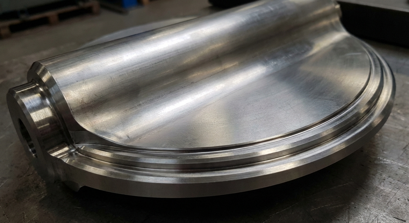
The geometry and profile of the disc are the primary physical factors that determine the level of turbulence and energy loss. A streamlined, airfoil-shaped disc will significantly lower the pressure drop through butterfly valve installations compared to a standard flat plate design. Because the disc remains in the flow stream even when fully open, its cross-sectional area is a critical variable in your flow calculations.
Aerodynamic Disc Profiles
Modern high-performance discs are engineered to allow fluid to pass with minimal disruption. This reduces the wake behind the disc, which is the leading cause of downstream pressure loss.
Obstruction and Flow Area
You might wonder if a few millimeters of thickness truly matter in a large pipe.
- Thinner discs offer higher Cv values.
- Edge polishing reduces localized friction.
- Specialized “low-noise” designs break up high-velocity jets.
Key Takeaway: Disc geometry is a primary mechanical factor that determines the efficiency of the flow path.
| Disc Shape | Resistance Level | Best Application |
|---|---|---|
| Airfoil | Low | High Velocity |
| Standard Flat | Moderate | General Utility |
| Thick Reinforced | High | High Pressure |
Optimizing disc selection is the most cost-effective way to improve the hydraulic efficiency of your system.
4. Do offsets reduce pressure drop through butterfly valve?
Eccentric designs, such as double or triple offset valves, reduce pressure loss by moving the stem and disc away from the center of the flow. By clearing the central path, these designs provide a much cleaner flow profile and a lower pressure drop through butterfly valve units than concentric versions. This configuration allows for higher Cv values while maintaining superior sealing capabilities in demanding industrial environments.
Concentric vs. Eccentric Flow
Concentric valves are simple, but the stem passes directly through the center of the disc. This creates a permanent split in the flow that generates constant turbulence.
The Triple Offset Advantage
It gets better: triple offset valves eliminate seat friction during opening and closing.
- Reduced friction preserves the disc profile.
- Unobstructed paths lead to maximum Cv.
- Metal seats handle higher pressures without compromising flow.
Key Takeaway: Choosing between concentric and eccentric designs is a strategic decision between initial cost and long-term flow efficiency.
| Design Type | Flow Efficiency | Sealing Capability |
|---|---|---|
| Concentric | Standard | Resilient Seat |
| Double Offset | High | High Performance |
| Triple Offset | Superior | Metal-to-Metal |
Selecting an offset design often pays for itself through reduced energy costs over the life of the valve.
5. What formula finds pressure drop through butterfly valve?
The industry standard formula for liquid flow relates flow rate, specific gravity, and the flow coefficient to determine energy loss. To calculate the pressure drop through butterfly valve components, you use the equation ΔP = SG * (Q / Cv)^2. This formula allows you to input your desired flow rate and the manufacturer’s Cv rating to find the exact pressure loss in PSI.
Breaking Down the Variables
Understanding each part of the equation is necessary for accurate calculations in the field. Specific gravity is a key variable that changes based on the fluid’s temperature and composition.
Calculating for Different States
Believe it or not, the calculation changes significantly when you move from liquids to gases.
- Liquids use the standard Cv formula.
- Gases require adjustments for compressibility.
- Steam calculations include specific volume factors.
Key Takeaway: Mastering the standard Cv formula allows for precise valve sizing and system optimization.
| Input | Description | Unit |
|---|---|---|
| Q | Flow Capacity | GPM |
| ΔP | Delta Pressure | PSI |
| Cv | Flow Coefficient | Dimensionless |
Using the correct formula ensures that your system maintains enough pressure to reach the final discharge point.
6. Do materials impact pressure drop through butterfly valve?
The surface finish and material of the valve body and disc play a significant role in determining skin friction and boundary layer turbulence. Using smooth materials or coatings reduces the pressure drop through butterfly valve hardware by allowing fluid to glide over surfaces with minimal resistance. Conversely, rough or corroded surfaces create micro-turbulences that steal energy from the flow and lower the effective Cv of the valve.
Surface Roughness and Friction
The “roughness” of the valve lining impacts the boundary layer of the fluid. Smoother surfaces like polished stainless steel facilitate laminar flow, which is the most efficient flow state.
Impact of Wear and Corrosion
Notice the difference: a brand-new valve always performs better than one with internal scaling.
- Epoxy coatings prevent mineral buildup.
- PTFE liners provide ultra-low friction.
- Corroded metal increases resistance over time.
Key Takeaway: Material choice affects both the longevity of the valve and its long-term flow efficiency.
| Material | Surface Finish | Friction Level |
|---|---|---|
| Polished Steel | Mirror | Lowest |
| Cast Iron | Matte | Moderate |
| PTFE Lined | Smooth | Minimum |
Investing in high-quality materials ensures that your Cv values remain stable over years of continuous operation.
7. When is the pressure drop through butterfly valve minimized?
Minimum pressure loss is always achieved when the valve is in the 90-degree, or fully open, position. At this angle, the disc is parallel to the fluid stream, which results in the lowest possible pressure drop through butterfly valve installations. Any deviation from this fully open position increases the obstruction in the pipe, causing the Cv to drop and the resistance to rise exponentially.
The Throttling Curve
The Cv of a butterfly valve does not increase linearly as it opens. Small changes in the disc angle at low positions have massive effects on the pressure loss.
Optimal Operating Range
You should keep this in mind: most butterfly valves are designed to throttle between 30 and 70 degrees.
- Below 20 degrees, high-velocity jetting occurs.
- Above 80 degrees, the valve acts as a full-port device.
- The 90-degree position offers the maximum Cv.
Key Takeaway: Operating the valve in its optimal “sweet spot” ensures the best balance of control and efficiency.
| Opening Angle | Flow Capacity | Turbulence Level |
|---|---|---|
| 0° – 30° | Very Low | Extremely High |
| 40° – 70° | Moderate | Medium |
| 80° – 90° | Maximum | Lowest |
For systems requiring high efficiency, ensure your actuators are calibrated to reach the full 90-degree open position.
8. Does sizing control pressure drop through butterfly valve?
Proper valve sizing is the most critical factor in managing energy loss and ensuring stable flow control across the system. An oversized valve may seem beneficial for flow, but it often leads to a higher pressure drop through butterfly valve seats because it must operate nearly closed to achieve control. Conversely, an undersized valve acts as a permanent bottleneck, wasting pump energy and generating excessive heat within the fluid.
The Danger of Oversizing
If a valve is too large for the application, it will stay in a low-opening position to maintain the flow setpoint. This leads to seat erosion and “hunting” where the actuator cannot stabilize the pressure.
Optimizing for System Head
Finding the balance is key: you want a valve that provides just enough resistance to stabilize the system.
- Correct sizing prevents cavitation.
- It maximizes the usable range of the actuator.
- It ensures the lowest possible energy waste.
Key Takeaway: Proper sizing ensures that the valve operates within its most stable and efficient range.
| Sizing Status | Control Quality | Pressure Loss |
|---|---|---|
| Undersized | Poor | Excessive |
| Correct Size | Excellent | Optimized |
| Oversized | Sensitive | Minimal (Unstable) |
Always consult a manufacturer’s Cv table to match the valve size to your specific flow requirements.
9. What are the risks of pressure drop through butterfly valve?
Excessive pressure loss can lead to catastrophic mechanical failures, including cavitation, which literally eats away at metal components. When the pressure drop through butterfly valve orifices is too high, the fluid can reach its vapor pressure, forming bubbles that implode and pit the disc. These implosions cause severe vibration and noise that can damage surrounding instruments and weaken the pipe supports.
Understanding Cavitation and Noise
Cavitation is the “silent killer” of industrial valves. The resulting micro-jets of fluid can destroy a stainless steel disc in a matter of weeks if the pressure differential is not managed.
Energy and Operational Costs
This is the bottom line: every PSI of lost pressure is money wasted at the pump.
- High pressure drops increase electricity bills.
- Vibration leads to frequent seal replacements.
- Heat buildup can degrade temperature-sensitive fluids.
Key Takeaway: Monitoring the pressure drop through butterfly valve units is a vital part of predictive maintenance.
| Risk Factor | Mechanical Effect | Economic Impact |
|---|---|---|
| Cavitation | Pitting / Erosion | High Repair Cost |
| Vibration | Seal / Bearing Wear | Frequent Downtime |
| Heat | Fluid Degradation | Product Loss |
Ignoring these physical risks will eventually lead to unplanned system shutdowns and expensive emergency repairs.
10. Can maintenance fix pressure drop through butterfly valve?
Regular maintenance is the only way to ensure that your valve continues to operate at its original design Cv. Over time, debris buildup and actuator misalignment can significantly increase the pressure drop through butterfly valve paths, reducing overall system performance. By cleaning the internal surfaces and recalibrating the stroke of the actuator, you can restore the valve to its peak hydraulic efficiency.
Inspecting for Scale and Debris
Mineral deposits can accumulate on the leading edges of the disc, effectively increasing its thickness and resistance. Periodic flushing or manual cleaning is necessary to maintain the flow area.
Actuator Calibration and Alignment
The truth is: if your actuator only opens to 85 degrees, you are losing significant flow capacity.
- Check the 90-degree stop annually.
- Ensure the disc is perfectly parallel to flow.
- Replace worn seats to prevent internal leaks.
Key Takeaway: Proactive maintenance preserves the original Cv and minimizes the pressure drop through butterfly valve components.
| Maintenance Task | Frequency | Benefit |
|---|---|---|
| Visual Check | Monthly | Early Detection |
| Stroke Test | Quarterly | Calibration |
| Internal Cleaning | Annually | Restored Cv |
A well-maintained valve ensures that your system calculations remain accurate throughout the equipment’s lifecycle.
Conclusion
Mastering the complexities of flow coefficients and pressure loss is vital for any modern industrial fluid system. If you need expert assistance in sizing your next project or selecting high-performance hardware, contact us today to speak with an engineering specialist. At RuitoFlow, we are dedicated to providing precision-engineered valve solutions that empower global industries through superior flow control and unmatched reliability.
Frequently Asked Questions
- Can I use a butterfly valve for continuous throttling?
Direct statement: Yes, you can use them for throttling as long as you operate within the 30 to 70-degree opening range. Operating outside this range increases the risk of cavitation and poor control, while operating within it allows for stable flow management. - What’s the best way to convert Cv to the metric Kv value?
Direct statement: The best method is to multiply your Cv value by 0.865 to obtain the equivalent Kv rating. This conversion is necessary when working with metric system specifications where flow is measured in cubic meters per hour at a 1 bar pressure drop. - How do I know if my valve is causing cavitation?
Direct statement: You can identify cavitation by listening for a sound similar to “gravel” passing through the pipe or by detecting high-frequency vibrations. These physical signs indicate that the pressure drop across the valve has caused fluid to reach its vapor pressure. - Can I reduce pressure loss by changing the disc material?
Direct statement: You can reduce loss by selecting materials with smoother surface finishes or low-friction coatings like PTFE. These materials reduce the skin friction of the fluid, effectively increasing the Cv and lowering the resistance through the valve body. - How do I know if I should choose a triple offset valve?
Direct statement: You should choose a triple offset valve if your application involves high pressures, extreme temperatures, or requires a zero-leakage metal-to-metal seal. These valves provide a more unobstructed flow path and superior durability compared to standard concentric designs.