
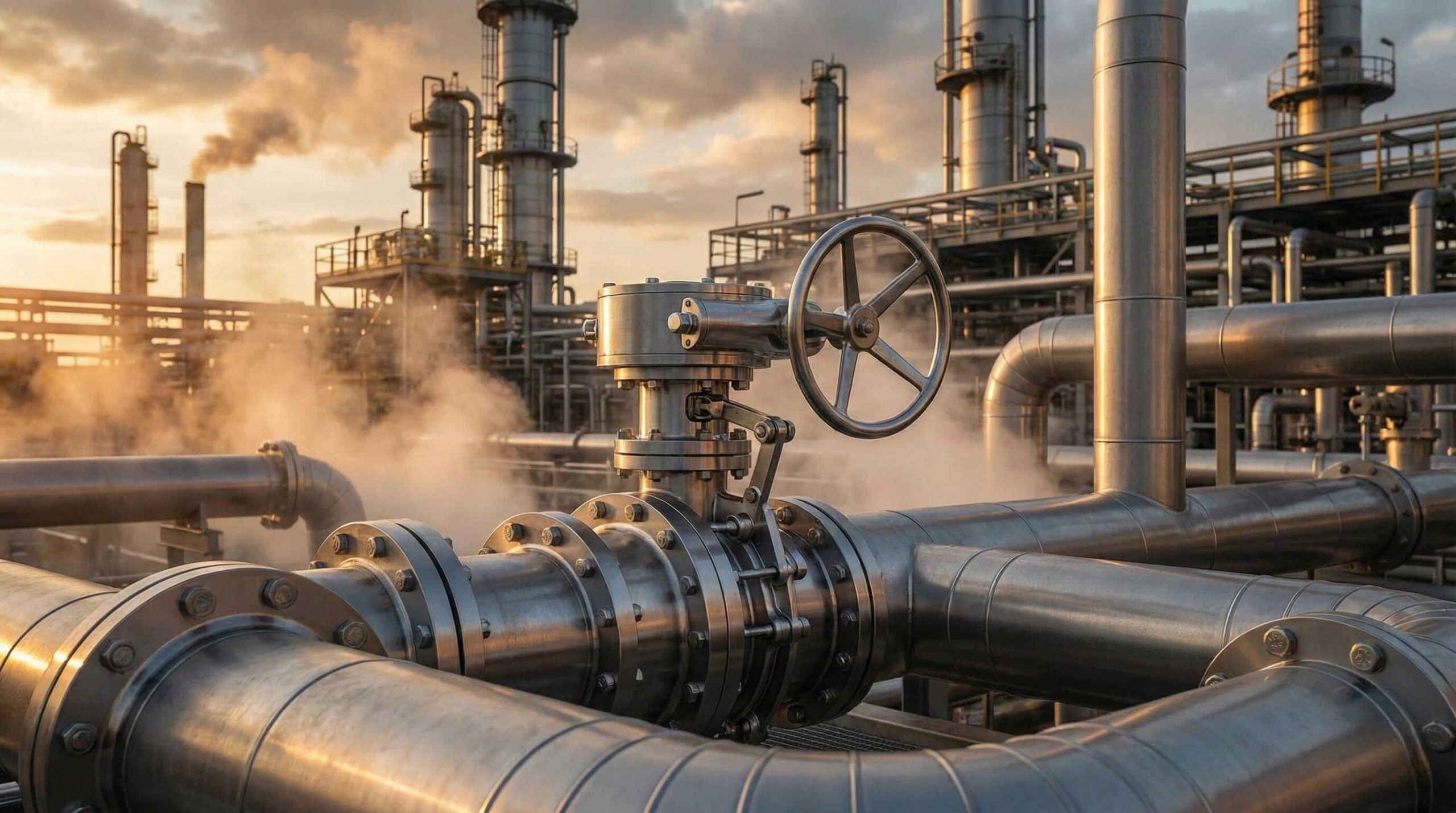
Dealing with frequent valve failures in your industrial piping system can feel like a never-ending nightmare for any plant manager or maintenance engineer. You install a standard valve hoping it will handle the pressure, but months later you face dangerous leaks, seized stems, and costly operational downtime that disrupts your entire production schedule. Here is the brutal truth: relying on general-purpose valves in high-stress environments frequently leads to catastrophic interruptions and safety hazards that your facility simply cannot afford to risk.
Fortunately, there exists a robust engineering solution designed explicitly to withstand these rigorous challenges without failing under pressure. High-performance double offset butterfly valves provide the exceptional durability and tight sealing capabilities you require without the excessive weight and bulk of traditional gate or globe valves. This comprehensive guide breaks down the specific components that make this technology reliable, helping you understand how each part contributes to a leak-free system. By mastering the anatomy of these valves, you ensure better selection and significantly longer service life for your critical applications.
1. What defines the high-performance butterfly valve structure?
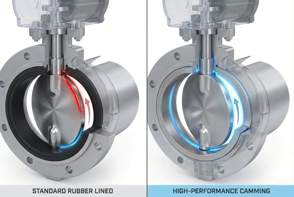
Here’s the deal: grasping the core definition of this specific valve type serves as the first step toward optimizing your facility’s flow control. A high-performance butterfly valve differs significantly from a standard rubber-lined resilient seated valve found in basic water applications. The “structure” here refers to a robust design engineered to handle higher pressures and extreme temperatures, often utilizing a specific double offset geometry. This configuration moves the shaft axis away from the centerline of the disc and the pipe, creating a necessary camming action during operation.
You need to recognize that this advanced structure does more than just hold back fluid; it actively reduces operational friction. In a standard concentric valve, the disc rubs against the seat for the entire travel range, causing rapid wear. However, the high-performance structure allows the disc to “lift” off the seat almost immediately upon opening. This reduction in physical contact decreases wear and tear significantly. Consequently, you receive a valve that lasts longer and requires less torque to operate, which allows for smaller, more cost-effective actuators.
| Feature | Standard Resilient Seated | High Performance Double Offset |
|---|---|---|
| Shaft Position | Centered in disc and body | Offset from disc and body center |
| Seat Friction | Continuous rubbing | Cam action (lifts off seat) |
| Pressure Rating | Low to Medium | High (ASME Class 150/300/600) |
| Life Cycle | Moderate | Extended due to reduced wear |
| Service | General Water/Air | Steam, Hydrocarbons, Chemicals |
2. How does the body style affect the butterfly valve structure?
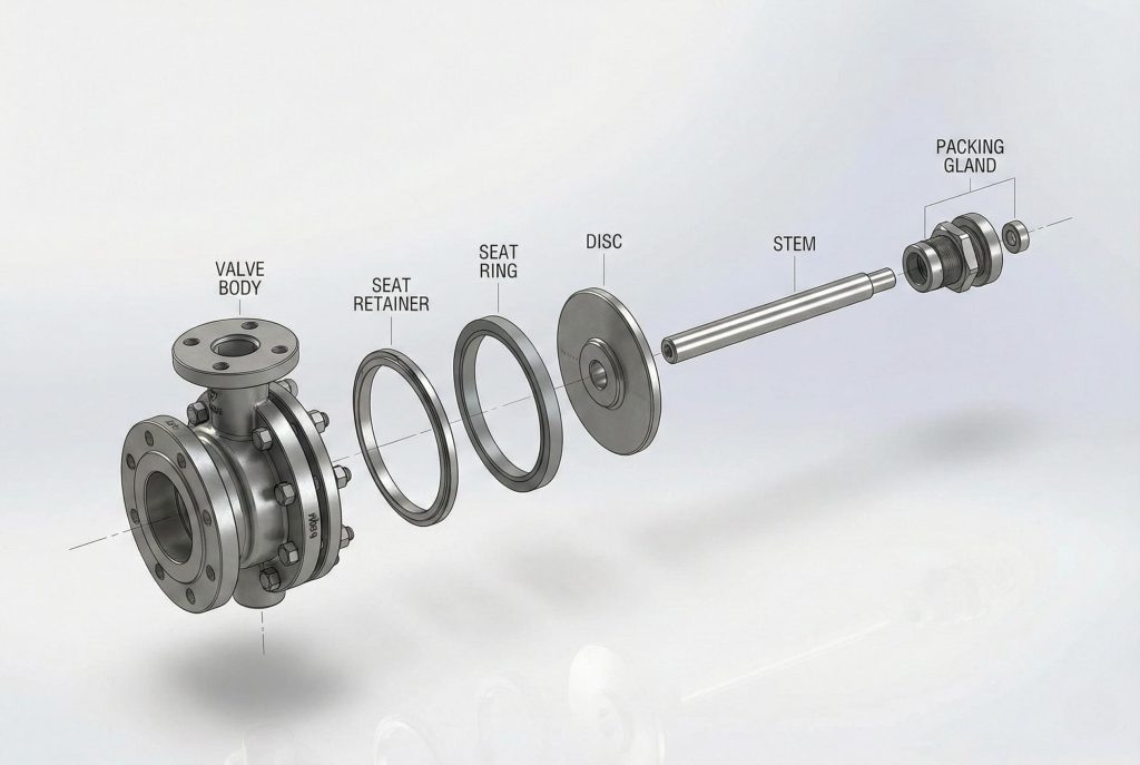
The body acts as the primary pressure boundary, housing all internal components and connecting directly to your complex piping system. When analyzing the butterfly valve structure, you will typically encounter two distinct body styles: wafer and lug. You might be wondering, does the choice of body style really change the actual performance? While the internal flow control mechanism remains similar, the installation and structural integrity capabilities differ vastly between these two options.
Wafer bodies function by being sandwiched between two pipe flanges, utilizing long bolts that pass from one flange to the other, surrounding the valve body completely. This design remains lightweight and economical, making it ideal for systems where weight reduction is a primary concern. On the other hand, lug bodies feature threaded holes matching the flange pattern. This allows you to bolt the valve directly to a single flange. Why does this matter? It enables dead-end service, meaning you can remove downstream piping for maintenance without draining the entire upstream system, a critical feature for many industrial applications.
3. Why is the disc design vital to the butterfly valve structure?
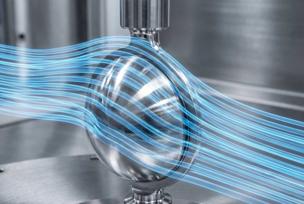
The disc functions as the flow-regulating element, acting effectively as the gatekeeper of your process media. In the context of a high-performance butterfly valve structure, the disc is not merely a flat plate; it represents a precision-engineered component often cast with a spherical profile. This shape remains critical because it must interact perfectly with the seat to ensure a bubble-tight seal when closed, while offering minimal resistance to flow when fully open.
It gets better: modern disc designs focus heavily on advanced hydrodynamics. A well-designed disc minimizes turbulence and pressure drop across the valve, which saves significant energy in large pumping systems. Furthermore, the disc must possess enough strength to withstand the full differential pressure of the line without deforming. Manufacturers often treat the edge of the disc—the sealing surface—with hardening processes or chrome plating. This treatment protects the disc from erosion caused by high-velocity fluids and prevents scratching that could otherwise compromise the seal integrity.
4. How does the stem connect within the butterfly valve structure?
The stem, or shaft, serves as the transmission line of the valve, transferring torque directly from the actuator to the disc. A critical weak point in older valve designs often involved how the stem connected physically to the disc. In the modern butterfly valve structure, engineers have moved away from invasive connection methods that create potential leak paths or structural weaknesses. You want a connection that provides zero hysteresis, meaning the disc moves exactly when the stem moves.
Historically, taper pins were driven through the stem and disc to lock them together securely. What is the catch? This required drilling holes through the shaft, reducing its strength, and the pins could loosen over time due to vibration. High-performance designs now often utilize a splined or square connection. In this setup, the stem engages with matching splines inside the disc hub. This “floating” disc design allows the disc to self-center within the seat, ensuring a perfect seal every time without compromising the structural integrity of the shaft.
| Connection Type | Pros | Cons |
|---|---|---|
| Taper Pin | Traditional, easy to manufacture | Weakens shaft; pins can loosen/leak |
| Splined/Square | High torque transmission; no shaft penetration | Requires precise machining; higher cost |
| Double D | Good for smaller sizes; simple | Can wear at corners under high cycle |
| Keyed | Strong mechanical lock | Stress concentrations at keyway |
5. Where is the seat located in the butterfly valve structure?
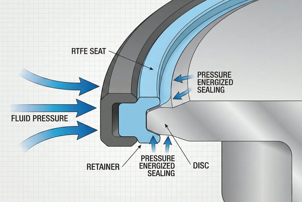
The seat represents the component responsible for the actual sealing capability of the valve. In the high-performance butterfly valve structure, the seat is retained in the body and interacts with the offset disc. Unlike rubber-lined valves where the seat constitutes the entire interior liner, high-performance seats are separate rings, usually accessible for replacement. This modularity offers a massive advantage for maintenance and long-term asset management.
Ready for the good part? These seats utilize the system pressure to assist in sealing. When the valve is closed and pressure applies, the seat becomes energized and pushes firmer against the disc edge. Materials vary widely based on application. You might use PTFE (Teflon) or RTFE for superior chemical resistance and tight shutoff in standard temperatures. For extreme heat or abrasive conditions, metal seats (often Inconel or Stainless Steel) are employed. Fire-safe designs often combine both, using a soft seat for normal operation and a backup metal seat that engages if the soft insert burns away.
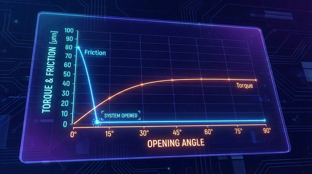
6. How does the double offset improve the butterfly valve structure?
We briefly mentioned the offset earlier, but it deserves a deeper look to understand its full value. The “double offset” description refers to two specific geometric shifts in the butterfly valve structure. First, the shaft is offset from the centerline of the disc seat. Second, the shaft is offset from the centerline of the pipe bore. So, what is the result? These two offsets work together to create a unique cam-like motion for the disc.
As the valve opens, the disc lifts off the seat almost instantly—typically within the first few degrees of rotation. This eliminates the friction and scraping that destroys seats in concentric valves. Because the disc only contacts the seat at the final point of closure, wear is minimized, and the life of the valve is extended significantly. This geometry also lowers the torque required to open and close the valve, which saves you money on automation costs by allowing for smaller actuators. For more on how this impacts your industry, check our oil and gas applications.
| Offset Type | Description | Benefit |
|---|---|---|
| First Offset | Shaft is behind the plane of the seat | Allows continuous sealing surface |
| Second Offset | Shaft is off-center from pipe bore | Creates cam action; lifts disc off seat |
| Result | Combined geometry | Zero friction during travel; lower torque |
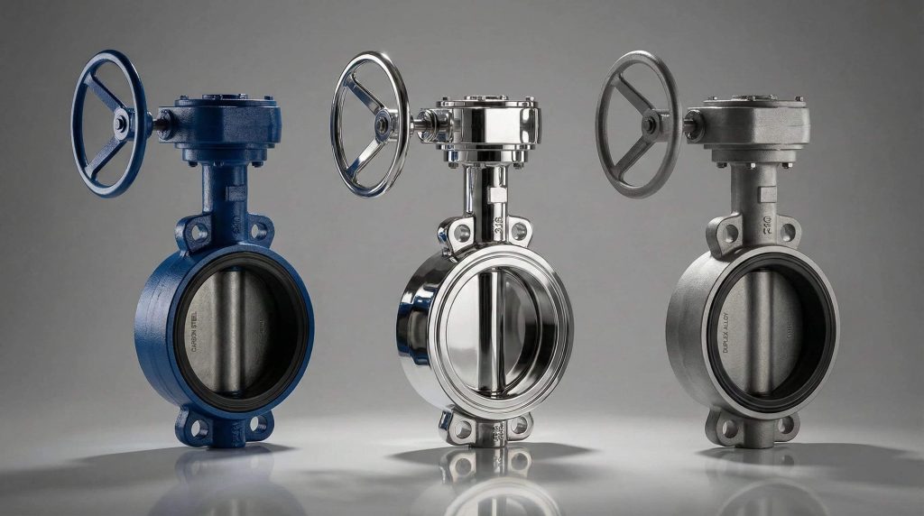
7. What materials make up the butterfly valve structure?
Selecting the correct materials is just as important as the mechanical design itself. The integrity of the butterfly valve structure depends on the compatibility of the metal and soft goods with your specific media. Standard carbon steel (WCB) serves as the workhorse for general industrial applications, offering strength and durability at a reasonable cost. However, it requires coating to prevent external corrosion.
For more aggressive environments, Stainless Steel (CF8M/316) is the standard upgrade. Here is a key fact: The body, disc, and stem do not always have to be the same material. It is common to see a Carbon Steel body with a Stainless Steel disc and stem to save costs while ensuring the wetted parts are corrosion-resistant. For seawater or highly corrosive chemical applications, you might need exotic alloys like Duplex Stainless Steel, Monel, or Hastelloy. The seat materials (as discussed previously) must also be chemically compatible to prevent swelling or degradation. You can view our specific butterfly valve products to see these material options.
8. How does packing seal the butterfly valve structure?
While the seat seals the line, the packing seals the environment. Preventing leakage from the stem area is critical for safety and strict environmental compliance. In the butterfly valve structure, the packing box sits around the upper stem. This area contains a series of flexible rings compressed against the smooth shaft and the stuffing box wall to block fluid from escaping upwards.
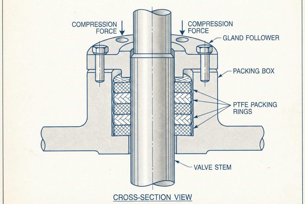
This is where it gets interesting: High-performance valves often feature adjustable packing glands. If a leak develops over time due to wear or thermal cycling, maintenance personnel can simply tighten the gland bolts to re-compress the packing and stop the leak. Typical packing materials include braided PTFE for standard service or Graphite for high-temperature and fire-safe applications. Advanced designs may include live-loading, where spring washers (Belleville washers) maintain constant pressure on the packing even as it wears.
| Feature | Function |
|---|---|
| Packing Rings | Primary barrier against stem leakage. |
| Gland Follower | Compresses the packing rings downwards. |
| Belleville Washers | Maintains tension (Live Loading) during thermal cycles. |
| Lantern Ring | Optional spacer for leak detection ports. |
| Anti-Extrusion Ring | Prevents packing material from squeezing out gaps. |
9. Can actuators fit easily onto the butterfly valve structure?
Automation functions as the heartbeat of modern processing plants. The butterfly valve structure is inherently designed to be actuator-friendly. Most high-performance valves come with a top mounting pad that conforms to ISO 5211 standards. This standardization is crucial because it allows you to mount almost any brand of pneumatic, electric, or hydraulic actuator directly to the valve without expensive custom brackets.
Because these valves are “quarter-turn” (90-degree rotation), they pair perfectly with rack-and-pinion or scotch-yoke pneumatic actuators. Why is this a benefit? It provides fast response times for emergency shutdown (ESD) systems. The low torque requirements driven by the offset design mean you can use smaller, less expensive actuators compared to a ball or gate valve of the same size. This compactness acts as a major advantage when installing valves in tight spaces or on skid-mounted equipment.
10. How does maintenance rely on the butterfly valve structure?
No mechanical device lasts forever, but the design of your valve dictates how painful the repair process will be. The modular nature of the high-performance butterfly valve structure allows for relatively easy servicing. Unlike welded-in valves, the seat in these units acts as a replaceable component held in place by a retainer ring or insert at the face of the body. This means you can replace a worn seat without scrapping the entire valve body.
Here is the bottom line: You can often remove the retainer, slide out the old seat, and install a new one with standard tools. The split-shaft or splined-shaft designs mentioned earlier also facilitate disassembly. By removing the actuator and the packing gland, the stem can be inspected for twisting or wear. However, always ensure the line is depressurized and drained before attempting any maintenance. Proper training on the specific anatomy of your valve model is essential for safe and effective repairs. For detailed inquiries, please visit our contact page.
| Maintenance Task | Frequency | Difficulty |
|---|---|---|
| Packing Adjustment | As needed (visual check) | Low (Wrench only) |
| Seat Replacement | End of cycle life | Medium (Requires removal) |
| Actuator Check | Monthly/Quarterly | Low |
| Disc Inspection | During shutdowns | Medium |
| Full Rebuild | Rare (Yearly+) | High |
Conclusion
Understanding the anatomy of a high-performance double offset butterfly valve empowers you to make smarter decisions for your facility. By recognizing how the offset geometry reduces wear, how the seat materials ensure tight shutoff, and how the body style impacts installation, you can select the right component for the right job. These valves offer a superior balance of durability, maintenance ease, and cost-efficiency compared to traditional valve types.
Do not let valve selection be a guessing game. If you are ready to upgrade your system reliability and stop worrying about leaks, take the next step. Visit our specific about us page today to speak with an expert about your specific application requirements. We are here to help you solve your flow control problems for good.
FAQ
Q1: Can I use high-performance butterfly valves for steam applications?
Yes, absolutely. Because the butterfly valve structure allows for metal or reinforced PTFE seats, they handle the high temperatures and pressures of steam much better than standard rubber-lined valves.
Q2: What is the best body style for end-of-line service?
The lug style body is the best choice. Its threaded inserts allow it to be bolted to a single upstream flange, holding pressure even if the downstream piping is removed.
Q3: How do I know if the valve is open or closed?
You can check the position indicator on the top of the stem or actuator. In the butterfly valve structure, the stem flat or the indicator flag typically aligns parallel with the pipe when open and perpendicular when closed.
Q4: Is a double offset valve unidirectional or bidirectional?
Most are bidirectional, but they often have a “preferred” flow direction. The structure seals better in one direction (flow assisting the seat), so checking the flow arrow on the body is crucial for optimal performance.
Q5: How often should I replace the seat?
It depends on your cycle frequency and media. However, the high-performance structure is designed to minimize wear, so seats often last for tens of thousands of cycles before replacement is necessary.