Butterfly valve torque standards and testing methods represent the technical protocols used to ensure that a valve opens and closes reliably under specific pressure differentials. Selecting an undersized actuator leads to stalled production and valve failure, while oversizing results in unnecessary capital expenditure and excessive wear on the valve stem. A single torque mismatch can cause leakage, internal component fatigue, or total system downtime during critical high-pressure cycles, damaging your facility’s reputation for reliability. By mastering the butterfly valve actuator torque calculation and adhering to international testing standards, you can ensure 100% sealing integrity and optimal actuator lifespan.
What is butterfly valve actuator torque calculation?
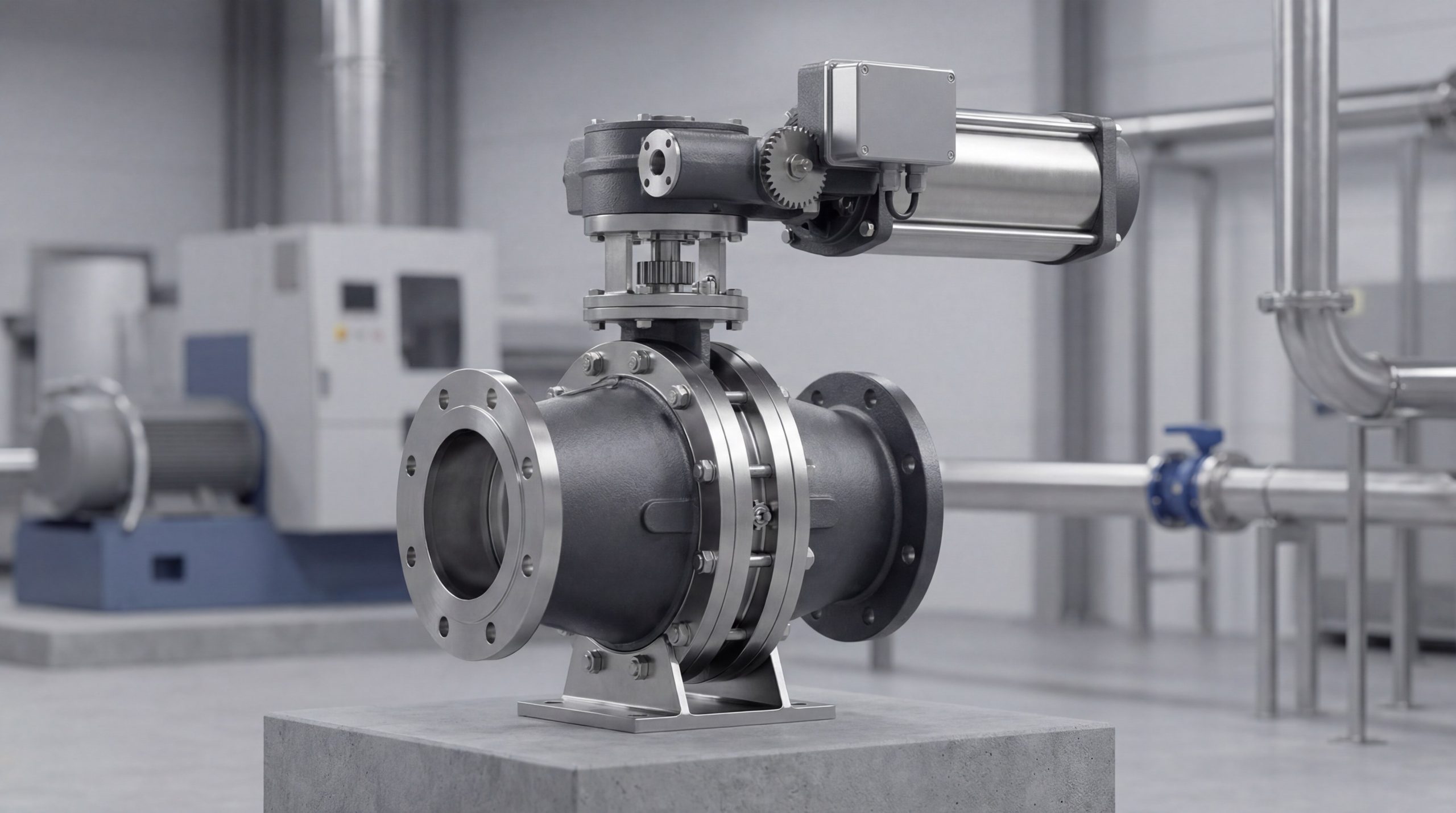
The butterfly valve actuator torque calculation is a technical process used to determine the exact force required to rotate a valve disc from the fully closed to the fully open position. This procedure accounts for the resistance provided by the seat, the bearing friction, and the dynamic forces of the flowing media. Our high-performance butterfly valve range relies on these precise values to ensure reliable operation under varying line pressures.
Defining the components of torque?
Think about it: torque is not a single static number, but rather the sum of multiple resistive forces acting on the valve shaft. You must evaluate the interplay between mechanical friction and hydraulic resistance to arrive at a safe operational figure.
- Seating Torque: The force required to compress the disc into the seat for a bubble-tight shutoff.
- Bearing Friction: Resistance generated between the stem and the bushings during rotation.
- Dynamic Torque: The impact of fluid velocity acting against the disc surface area.
Key Takeaway: Torque is measured in Newton-meters (N·m) and serves as the fundamental baseline for all actuator sizing and selection.
| Component | Description | Calculation Priority |
|---|---|---|
| Ts (Seat) | Initial breakout force from the seal | High |
| Tb (Bearing) | Constant frictional resistance | Medium |
| Td (Dynamic) | Force from fluid velocity | Variable |
This breakdown identifies the specific mechanical hurdles an actuator must overcome during a full 90-degree cycle.
Why is accurate torque calculation so critical?
Accurate butterfly valve actuator torque calculation prevents premature actuator burnout and ensures that the valve can overcome “breakout torque” after long periods of inactivity. If the torque is underestimated, the valve may fail to close during an emergency, leading to catastrophic system leaks. Conversely, over-torquing can shear the valve stem or deform the seating material, reducing the equipment’s service life.
How does it impact valve lifecycle?
Here is the deal: precision in torque selection directly correlates to the longevity of your fluid control system by preventing mechanical fatigue. When you match the actuator force to the valve’s actual requirements, you reduce the strain on internal components.
- Wear Reduction: Minimizes the friction-induced erosion of the valve seat and stem seals.
- Energy Efficiency: Ensures automated systems use the minimum required power for operation.
- Safety Assurance: Guarantees that the valve can reach its “fail-safe” position under maximum load.
Key Takeaway: Proper sizing through accurate data protects both the actuator and the valve seat from unnecessary mechanical fatigue and failure.
| Risk Factor | Impact of Under-sizing | Impact of Over-sizing |
|---|---|---|
| Operational | Valve stalls or fails to seat | Excessive stem wear and seat damage |
| Financial | Replacement costs for failed actuators | Higher initial CAPEX for larger units |
| Safety | Failure of emergency shut-down | Potential mechanical shearing |
Maintaining a balanced torque profile is essential for achieving the 25-year operational life expectancy required in critical infrastructure.
Which factors influence butterfly valve torque?
Several variables influence the butterfly valve actuator torque calculation, including seat material, media temperature, and the specific geometry of the valve disc. Unlike a standard gate valve, the torque in a butterfly valve varies significantly as the disc moves through different opening angles. You must consider the specific environmental conditions of your pipeline to avoid operational discrepancies.
What are the primary torque drivers?
The bottom line? You must account for environmental and mechanical factors that fluctuate during the valve’s service life. Changes in fluid viscosity or the presence of particulates can drastically alter the friction coefficient of the seat.
- Differential Pressure ($\Delta P$): Higher pressure increases the force pushing the disc against the seat.
- Media Type: Lubricating fluids like oil require less torque than dry media or abrasive slurries.
- Stiction: Infrequent operation can cause the disc to “stick” to the seat, increasing breakout torque.
Key Takeaway: Always apply a safety factor (typically 20-30%) to account for potential increases in friction over time due to scaling or seat aging.
| Variable | Impact on Torque | Recommendation |
|---|---|---|
| High Pressure | Increases linearly | Use high-strength stem materials |
| Dry Media | Increases significantly | Apply a 1.5x multiplier to wet torque |
| Corrosion | Increases over time | Select SS316 or PTFE-lined options |
Analyzing these drivers allows you to predict the “worst-case” scenario for the valve’s operational environment.
How do you calculate required actuator torque?
To perform a butterfly valve actuator torque calculation, you must use the standard formula $Ta = Ts + Tb + Td$, which combines seat, bearing, and dynamic torque components. This formula ensures that the actuator has enough power to break the seal and move the disc against the flow of the media. Theoretical calculations provide a baseline, but physical testing remains the gold standard for high-pressure industrial applications.
What is the standard formula breakdown?
Look: each variable in the equation represents a specific resistance that the actuator must overcome to ensure a successful cycle. By isolating these components, you can identify which part of the valve assembly requires the most energy during movement.
- Ts (Seat Torque): Force calculated based on the friction between the disc and the elastic seat.
- Tb (Bearing Torque): Friction between the shaft and the bushings, influenced by the shaft diameter.
- Td (Dynamic Torque): The force exerted by fluid flow, calculated using the $Td = Ct \cdot D^3 \cdot \Delta P$ formula.
Key Takeaway: Integrating these three components into a single $Ta$ value ensures the actuator can handle the highest load point in the cycle.
| Formula Element | Definition | Calculation Basis |
|---|---|---|
| $Ts$ | Seating Torque | Seat material friction coefficient |
| $Tb$ | Bearing Torque | Stem diameter and load |
| $Td$ | Dynamic Torque | Flow velocity and disc diameter |
Using a modular calculation approach allows for more accurate adjustments when upgrading seat materials or changing media types.
What are common torque measurement methods?
Testing through butterfly valve actuator torque calculation can be verified using manual torque wrenches, electronic sensors, or built-in actuator diagnostic tools. Integrating high-accuracy ball valve diagnostic techniques often helps in cross-referencing torque data for diverse industrial setups. These methods ensure that the theoretical values match the actual performance of the valve under real-world conditions.
Which digital tools ensure data accuracy?
It gets better: manufacturers now utilize advanced digital sensors to capture a complete “torque profile” of the valve during its 90-degree stroke. This data allows you to see exactly where resistance peaks, whether at the initial opening or the final seating stage.
- Electronic Torque Sensors: Provide real-time data capture with high precision for automated systems.
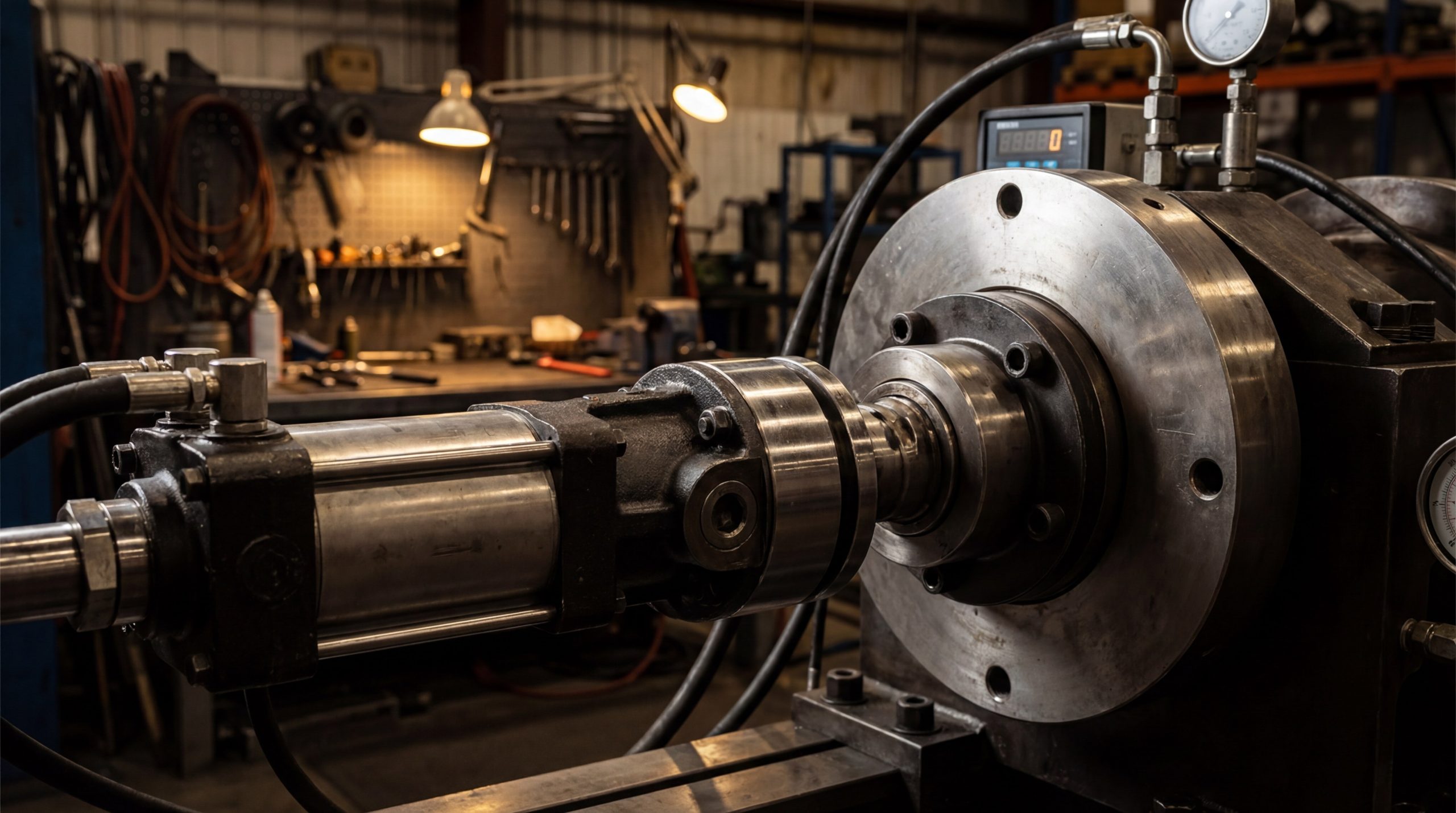
- Hydraulic Test Rigs: Simulate maximum differential pressure to verify the valve’s seating integrity.
- Calibrated Wrenches: Essential for field verification and manual audits during plant commissioning.
Key Takeaway: Digital measurement provides a “torque signature” that can identify seat wear or stem misalignment before a leak occurs.
| Measurement Tool | Accuracy Level | Best Use Case |
|---|---|---|
| Manual Wrench | +/- 5% | Field commissioning |
| Electronic Sensor | +/- 0.5% | Laboratory testing |
| Actuator Diagnostics | Continuous | Predictive maintenance |
Digital verification is the only way to guarantee that a valve meets the strict reliability requirements of the power generation and chemical sectors.
Are there standard torque charts for rubber seats?
Standard charts for butterfly valve actuator torque calculation provide torque values based on valve size and pressure ratings, such as PN10 or PN16. These charts are typically generated under “optimum” conditions using water as the lubricating media. For non-lubricating or dry media, you must apply specific multipliers to ensure the actuator is not underpowered for the task.
How should you interpret seating charts?
Wait, there’s more: you must distinguish between “wet” and “dry” torque values to avoid sizing an actuator that fails under low-lubricity conditions. Understanding these nuances ensures that your check valve and butterfly valve assemblies work in harmony without stalling.
- Wet Torque: Applied to water, oils, and other lubricating fluids that reduce friction.
- Dry Torque: Required for air, dry gases, or powders which increase seat resistance by up to 50%.
- Pressure Ratings: Torque increases as the PN rating rises, requiring more robust actuation.
Key Takeaway: Ensure you are using the correct column in the torque chart based on your specific media’s lubricating properties.
| Valve Size (DN) | PN10 Wet (N.m) | PN16 Wet (N.m) | PN16 Dry (N.m) |
|---|---|---|---|
| 50 (2″) | 13.9 | 15.1 | 24.2 |
| 100 (4″) | 37.1 | 39.8 | 72.8 |
| 200 (8″) | 173 | 192 | 330 |
| 300 (12″) | 429 | 490 | 799 |
Referencing standardized charts reduces the risk of human error during the initial engineering and procurement phase.
How does a Teflon seat affect torque values?
The butterfly valve actuator torque calculation for Teflon (PTFE) seats typically results in higher values compared to rubber due to the material’s inherent stiffness. While Teflon offers superior chemical resistance, its lower elasticity requires a higher seating force to achieve a bubble-tight seal. This trade-off is often necessary when handling aggressive acids or bases in chemical processing plants.
Why does PTFE require higher force?
Think about it: Teflon does not deform as easily as EPDM or NBR, meaning the disc must exert more pressure to create an airtight interface. You must factor in this increased resistance to avoid choosing an actuator that “trips” due to excessive torque load.
- Material Hardness: PTFE’s rigid structure requires a more powerful mechanical “squeeze” for sealing.
- Chemical Stability: Despite the higher torque, Teflon prevents seat degradation in corrosive environments.
- Friction Coefficient: Teflon has a unique friction profile that can increase when dry.
Key Takeaway: Choose Teflon for its chemical compatibility, but always budget for a larger and more robust actuator footprint.
| Valve Size (Inch) | PN6 Wet (N.m) | PN16 Wet (N.m) | PN16 Dry (N.m) |
|---|---|---|---|
| 2″ | 24.3 | 28.2 | 45.2 |
| 4″ | 65.3 | 74.3 | 136 |
| 8″ | 287 | 358 | 617 |
| 12″ | 694 | 916 | 1493 |
The increased torque of PTFE seats is a justifiable cost when the media’s corrosivity would destroy standard elastomer seals in weeks.
What role does the Kv value play in sizing?
While butterfly valve actuator torque calculation focuses on mechanical movement, the Kv value determines the hydraulic impact on the disc which influences dynamic torque. Much like sizing a globe valve for throttling, understanding the flow coefficient is essential for predicting the forces acting on the valve at various opening angles. The Kv value represents the flow rate in cubic meters per hour at a pressure drop of 1 bar.
How is flow linked to dynamic torque?
The truth is: flow velocity and dynamic torque are inextricably linked because the fluid acts as a lever against the valve disc. As the valve opens, the fluid velocity can create an “aerofoil” effect that either helps or hinders the actuator’s movement.
- Maximum Dynamic Torque: Usually occurs at a 70-80 degree opening angle where velocity is highest.
- Throttling Applications: Constant flow adjustments increase the cumulative wear on the actuator gears.
- Flow Capacity: High-Kv valves may require stronger actuators to close against high-velocity streams.
Key Takeaway: A valve with a high flow capacity may require a significantly stronger actuator to overcome dynamic forces during the closing cycle.
| Opening Angle | Kv (%) | Dynamic Torque Impact |
|---|---|---|
| 10° | Low | Minimal |
| 50° | Medium | Rising |
| 80° | High | Maximum |
Understanding the Kv relationship allows you to select an actuator that maintains control even during peak flow surges.
Which testing standards ensure reliability?
Compliance with standards like API 609 or ISO 5208 is vital for a valid butterfly valve actuator torque calculation and overall quality assurance. These benchmarks ensure that the torque values provided by the manufacturer are repeatable and verified under controlled laboratory conditions. Using standardized testing protocols protects your project from the risks associated with non-compliant, low-quality components.
What are the essential quality benchmarks?
Look: certification ensures that every valve in a batch performs identically, which is critical for synchronized automated systems. These standards define exactly how pressure should be applied and how leakage rates should be measured during the torque test.
- API 609: Governs the design and pressure-temperature ratings for industrial butterfly valves.
- ISO 5208: Standardizes the pressure testing procedures for all industrial metallic valves.
- EN 12266: Specifies the allowable leakage rates and the mandatory testing procedures for safety.
Key Takeaway: Never source a valve for critical industrial service without a certified torque test report that references international standards.
| Standard | Focus Area | Industry Requirement |
|---|---|---|
| API 609 | Design & Sealing | Oil & Gas |
| ISO 5208 | Pressure Testing | General Industrial |
| EN 12266 | Leakage Rates | European Municipal |
Adhering to these benchmarks is the only way to ensure the long-term mechanical reliability of your automated valve network.
How can I optimize actuator selection?
Optimization starts with a precise butterfly valve actuator torque calculation that accounts for the “worst-case” scenario in your pipeline. You must balance the need for safety with the desire for cost-efficiency to create a sustainable fluid control system. Our engineering team often uses these optimized protocols to prevent issues like water hammer or actuator burnout in municipal water networks.
What steps ensure perfect matching?
Here is the deal: follow a rigorous sequence of data collection and calculation to ensure your system operates flawlessly from day one. Skipping a single variable in the sizing process can lead to mechanical failures that cost thousands in unplanned downtime.
- Data Collection: Determine the maximum differential pressure, media type, and temperature range.
- Material Selection: Choose the seat and stem materials that match your media’s chemical profile.
- Safety Factor: Apply an industry-standard factor (20-50%) to the final $Ta$ calculation.
Key Takeaway: Consult with a technical expert to review your calculations before finalizing your procurement to ensure a 100% success rate.
| Optimization Step | Action | Outcome |
|---|---|---|
| Pressure Audit | Verify Max $\Delta P$ | Accurate $Ts$ values |
| Media Analysis | Check for Solids | Correct safety multiplier |
| Cycle Analysis | Determine Frequency | Proper actuator duty cycle |
By following this structured approach, you can eliminate the guesswork that leads to inefficient and unsafe valve operations.
FAQ Section
- Can I use the same torque value for dry and wet media?
No, you must use a higher multiplier for dry media in your calculation. Dry media increases friction significantly; you must use the specific “dry torque” value to avoid actuator failure and ensure complete sealing. - What’s the best safety factor to use for actuator sizing?
The industry standard is typically 20-30% for clean, lubricating fluids. However, for critical safety valves or media containing abrasive slurries, a safety factor of 50% is highly recommended to account for seat degradation. - How do I know if my actuator is undersized?
A judgment of “undersized” is usually made if the valve fails to reach the full closed position under pressure. You might also notice the actuator motor overheating or the valve “juddering” during the final degrees of rotation. - What’s the best way to verify torque in the field?
Using a calibrated manual torque wrench during the first commissioning cycle is the most reliable field verification method. This allows you to compare the real-world breakout torque against the manufacturer’s technical data sheets. - Can I calculate torque based only on the valve diameter?
No, diameter is only one of several critical variables. While size is important, line pressure and seat material are equally vital factors in the formula, as they directly dictate the amount of friction the actuator must overcome.
Conclusion
Selecting the right fluid control components requires more than just picking a size; it requires a deep dive into the mechanical forces at play. Whether you are dealing with undersized actuators that threaten production or oversized units that drain your budget, precision engineering is the only solution. RUITO is dedicated to providing traceable, high-reliability valve solutions that meet the world’s most demanding industrial standards. For a detailed technical consultation or to receive a custom quote for your project, please contact us today and speak with our senior valve engineers.