
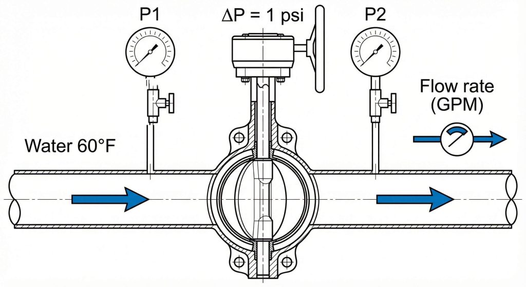
Understanding Butterfly Valve CV (Flow Coefficient) is the measure of how many US gallons of water at 60°F will flow through a valve with a pressure drop of exactly 1 psi. Inaccurate valve sizing frequently triggers catastrophic system failures, leading to costly downtime and equipment erosion in industrial piping. Selecting a valve based solely on pipe diameter often leads to excessive noise, cavitation, and premature seat wear that disrupts your entire operation. By utilizing professional butterfly valve design calculations, you can ensure hydraulic balance and long-term reliability for your fluid control systems.
What is Cv in butterfly valve design calculations?
The Cv value is a mathematical constant used to determine the flow capacity of a valve at a specific pressure drop. It allows engineers to predict how much liquid will pass through the system under various operational states. Mastering butterfly valve design calculations is essential for selecting the correct valve size for your application.
Why is the 1 psi standard used?
This standardized pressure drop provides a universal benchmark for comparing different valve types and sizes. It simplifies the complex physics of fluid dynamics into a single, manageable number for system designers.
- Enables direct comparison between valve brands.
- Simplifies pump head requirement estimates.
- Standardizes flow data across global projects.
The truth is: without this standard, matching valves to pumps would be a guessing game.
Key Takeaway: The Cv value represents the number of US gallons of water that will flow through a valve with a 1 psi pressure drop.
| Parameter | Unit | Definition |
|---|---|---|
| Cv | US GPM | Imperial flow coefficient |
| Kv | m³/h | Metric flow coefficient (Kv = Cv / 1.156) |
| ΔP | PSI | Pressure drop across the valve |
This table illustrates the relationship between imperial and metric flow coefficients used in global engineering.
Why does Cv impact butterfly valve design calculations?
Cv dictates your system’s performance by defining the relationship between flow rate and energy loss. Proper butterfly valve design calculations prevent energy waste by ensuring the valve doesn’t create unnecessary resistance. When the flow coefficient is correctly matched, the system maintains stable pressure and velocity.
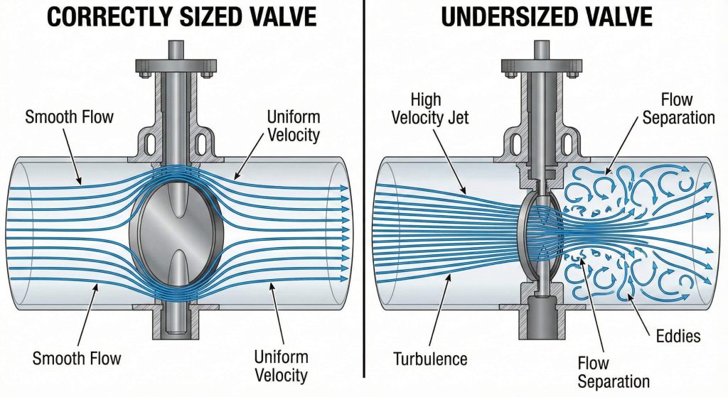
Does sizing affect valve longevity?
Correct sizing prevents common mechanical issues like seat erosion and stem vibration caused by excessive velocity. Valves that are too small force the fluid to move at high speeds, which can destroy internal seals.
- Reduces turbulent flow patterns.
- Minimizes vibration-induced fatigue.
- Prevents localized pressure spikes.
Think about it: a properly sized valve pays for itself through reduced maintenance costs.
Key Takeaway: Correct Cv selection prevents system inefficiencies such as cavitation and excessive vibration.
| Issue | Cause | Outcome |
|---|---|---|
| Cavitation | Cv too low | Rapid disc and seat erosion |
| Hunting | Cv too high | Poor control and frequent cycling |
| Noise | High velocity | Pipe fatigue and operator discomfort |
Maintaining the correct Cv avoids these three primary operational failures in industrial piping.
How to perform butterfly valve design calculations?
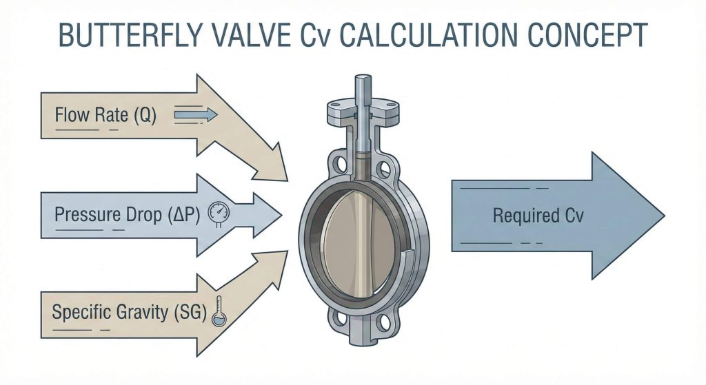
You calculate the required Cv by dividing the flow rate (GPM) by the square root of the pressure drop (PSI). This standard formula is the starting point for all professional butterfly valve design calculations involving liquid media. Adjustments are then made based on fluid density and specific gravity.
What about specific gravity?
The density of the fluid significantly alters the pressure drop required to move a specific volume. For fluids heavier than water, the required Cv must be increased to maintain the desired flow rate.
- Water has a specific gravity of 1.0.
- Oils often range from 0.7 to 0.9.
- Chemical slurries can exceed 1.2.
Believe it or not: ignoring specific gravity is the most common cause of undersized control valves.
Key Takeaway: Accurate calculations must account for the specific gravity of the media to ensure the valve performs under real-world conditions.
| Variable | Description | Common Range |
|---|---|---|
| Q | Flow Rate | 10 – 12,000 GPM |
| ΔP | Allowed Pressure Drop | 1 – 5 PSI |
| SG | Specific Gravity | 0.8 – 1.5 |
These three variables are the fundamental inputs required to determine the necessary valve capacity.
How do concentric butterfly valve design calculations vary?
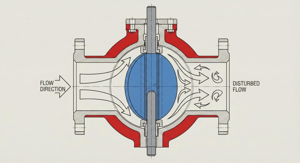
Concentric valves typically have lower Cv values because the stem passes directly through the center of the disc. This alignment increases the obstruction in the flow path compared to other designs. Consequently, butterfly valve design calculations for concentric models must account for this higher inherent resistance.
Is the center stem a bottleneck?
The center-stem design creates a divided flow path that induces minor turbulence at the trailing edge of the disc. While cost-effective, these valves are best suited for lower pressure applications where maximum Cv isn’t the primary concern.
- Simple, lightweight construction.
- Resilient seated for bubble-tight shutoff.
- Ideal for water treatment and HVAC.
In simpler terms: concentric valves prioritize sealing and cost over raw flow volume.
Key Takeaway: Concentric valves are ideal for low-pressure applications but may offer lower Cv than offset designs due to disc obstruction.
| Valve Size | Typical Max Cv | Application |
|---|---|---|
| 2″ (DN50) | 135 | HVAC Chilled Water |
| 4″ (DN100) | 600 | Potable Water Distribution |
| 6″ (DN150) | 1500 | Municipal Irrigation |
This data shows typical flow capacities for concentric valves used in standard utility services.
Are offset butterfly valve design calculations different?
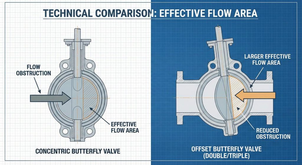
Offset valves provide higher Cv values by shifting the disc and stem away from the center of the pipe. This geometry reduces the surface area obstructing the fluid when the valve is fully open. Precise butterfly valve design calculations are required to leverage the high-performance capabilities of double and triple offset models.
Why use triple offset?
Triple offset designs use a cam-like action to lift the disc off the seat, reducing friction and wear. This leads to higher flow coefficients and superior sealing performance in high-temperature and high-pressure environments.
- Zero-leakage metal-to-metal seating.
- Extended service life in steam systems.
- Handles extreme pressure differentials.
Here is the kicker: offset valves offer the best flow-to-size ratio in the industry.
Key Takeaway: Eccentric valves provide higher Cv values and better durability in high-pressure differentials.
| Design Type | Cv Advantage | Main Benefit |
|---|---|---|
| Double Offset | Moderate (+15%) | Reduced Seat Wear |
| Triple Offset | High (+25%) | Extreme Temp/Pressure |
| High Performance | Variable | Corrosion Resistance |
Choosing an offset design significantly increases the hydraulic efficiency of large-scale industrial pipelines.
Do materials affect butterfly valve design calculations?
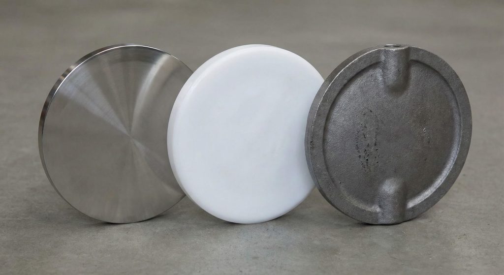
Material selection impacts surface roughness and disc thickness, both of which alter the flow coefficient. Smoother materials like stainless steel or PTFE-lined discs reduce friction during butterfly valve design calculations. Conversely, cast iron or roughly coated discs may increase turbulence and lower the effective Cv.
Does seat friction matter?
The interaction between the disc edge and the seat material determines the opening torque and the initial flow path. Harder seat materials allow for thinner disc profiles, which directly increases the available flow area.
- EPDM/NBR for general water service.
- PTFE for chemical compatibility.
- Metal seats for high-temperature stability.
Think about it: the smoother the disc, the less energy your pumps will consume.
Key Takeaway: Smoother internal surfaces and low-friction seat materials maximize the effective Cv of the valve.
| Material | Friction Factor | Best Use |
|---|---|---|
| SS316 (Polished) | Very Low | Food and Beverage |
| Ductile Iron | Moderate | Wastewater |
| PTFE Lined | Low | Corrosive Acids |
Matching the right material to your fluid ensures the valve maintains its design Cv over its lifetime.
How does opening angle change butterfly valve design calculations?
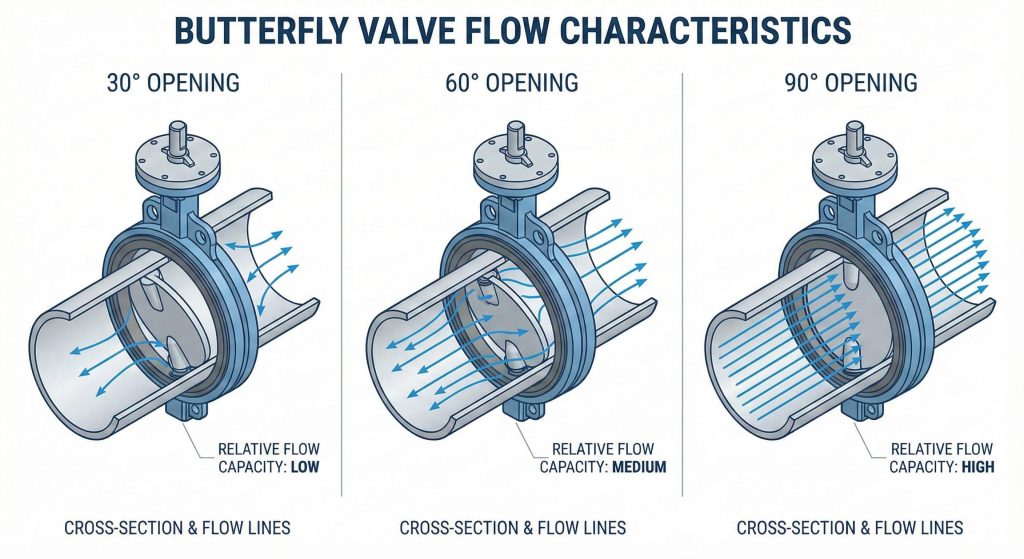
Cv values increase non-linearly as the butterfly valve disc rotates from 0 to 90 degrees. Most of the flow capacity is achieved between 30 and 70 degrees of opening, which is a critical factor in butterfly valve design calculations. Operating a valve too close to the seat can cause high-velocity “jetting” that damages the liner.
Is 60 degrees the sweet spot?
For throttling applications, engineers aim for a 60-degree opening to provide the best control resolution. This prevents the “hunting” effect where the actuator constantly over-corrects due to excessive sensitivity at small opening angles.
- 10° – 20°: Risk of seat erosion.
- 30° – 70°: Optimal control range.
- 90°: Maximum flow capacity.
In a nutshell: sizing a valve to run at 60% open during normal flow is best practice.
Key Takeaway: A butterfly valve achieves most of its flow capacity between 30 and 70 degrees of opening.
| Opening Angle | % of Max Cv | Flow Characteristic |
|---|---|---|
| 30 Degrees | 15% | Throttling Start |
| 60 Degrees | 55% | Optimal Control |
| 90 Degrees | 100% | Full Capacity |
Understanding this curve is vital for anyone using butterfly valves for automated process control.
Can actuation shift butterfly valve design calculations?
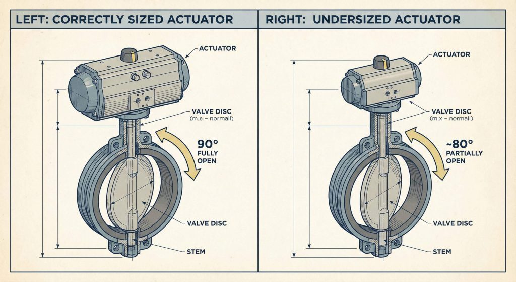
Actuators must provide enough torque and travel range to ensure the disc reaches the full 90-degree open position. If an actuator is undersized, the valve may only open to 80 degrees, significantly reducing the Cv predicted by your butterfly valve design calculations. Precise positioning is mandatory for maintaining the calculated flow rates.
Can pneumatic torque help?
Pneumatic actuators offer fast, consistent torque that ensures the valve moves past the high-friction “break-to-open” point. This reliability is essential for maintaining the hydraulic balance intended by the system’s design calculations.
- Quick response for emergency shutoff.
- Fail-safe options (Spring Return).
- Compatible with digital positioners.
But wait, there’s more: incorrect actuator sizing is a top cause of “phantom” pressure drops.
Key Takeaway: Properly sized actuators ensure the disc reaches the 90-degree position required for maximum Cv.
| Actuator Type | Speed | Control Precision |
|---|---|---|
| Manual Gear | Slow | Low |
| Pneumatic | Fast | Moderate |
| Electric | Moderate | High |
The choice of actuation directly impacts how reliably the valve achieves its rated flow coefficient.
How to troubleshoot butterfly valve design calculations errors?
Troubleshooting begins by comparing actual field pressure drops against your theoretical butterfly valve design calculations. If the measured flow is lower than expected, check for internal obstructions or incorrect valve orientation. Cavitation noise often indicates that the valve is undersized for the required flow rate.
Is cavitation a sign of bad sizing?
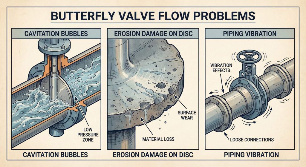
Yes, cavitation occurs when the local pressure drops below the fluid’s vapor pressure, causing bubbles to form and collapse. This destructive force indicates that the Cv is too low for the velocity of the media.
- Loud “gravel-like” noise.
- Heavy piping vibration.
- Pitted metal on the disc surface.
You might be wondering: can I fix this without replacing the valve? Usually, the only fix is resizing.
Key Takeaway: Regular inspection of the disc and seat is required to maintain the design flow coefficient over time.
| Symptom | Probable Cause | Fix |
|---|---|---|
| Low Flow | Debris in valve | Clean / Flush Line |
| Vibration | Disc instability | Verify torque/actuation |
| High ΔP | Valve undersized | Recalculate and replace |
Using this diagnostic framework helps identify sizing errors before they cause a total system shutdown.
Where to apply butterfly valve design calculations in plants?
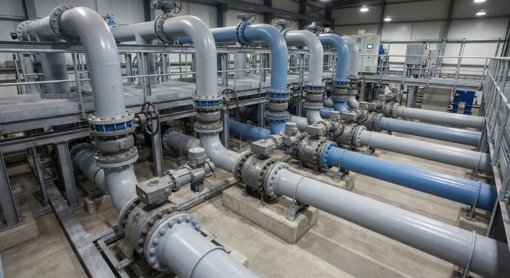
These calculations are critical in high-capacity flow applications like municipal water networks and chemical processing plants. Implementing accurate butterfly valve design calculations ensures that every component in a valve manifold works in synergy. Without these calculations, pump stations would waste enormous amounts of electricity fighting valve resistance.
Why prioritize water systems?
Municipal water systems rely on large-diameter butterfly valves to move millions of gallons daily. Even a 5% error in Cv calculation can lead to massive energy waste and potential water hammer issues during pump starts.
- Prevents energy loss in cooling towers.
- Optimizes chemical dosing accuracy.
- Protects sensitive filtration membranes.
The truth is: efficiency starts with the valve, not just the pump.
Key Takeaway: Proper installation prevents localized turbulence that can artificially reduce the effective Cv of the system.
| Industry | Primary Fluid | Typical Valve Size |
|---|---|---|
| Power Gen | Cooling Water | 24″ – 72″ |
| Chem Process | Corrosive Media | 4″ – 12″ |
| Municipal | Potable Water | 12″ – 48″ |
This table shows the diverse range of applications where flow coefficient accuracy is non-negotiable.
Conclusion
Mastering butterfly valve Cv and flow rate essentials is the cornerstone of building efficient, reliable industrial systems. By applying rigorous butterfly valve design calculations, you eliminate the guesswork that leads to cavitation, vibration, and energy waste. RUITO Industrial Valves is dedicated to providing the precision-engineered solutions you need to optimize your fluid control operations. Our vision is to empower engineers with the technical data and high-quality hardware required for seamless industrial performance.
Don’t let sizing errors compromise your project’s success. Contact us today to speak with our technical experts and receive a custom flow analysis for your next installation.
Frequently Asked Questions
Can I use a smaller valve than the pipe size to save costs?
Not recommended. While it saves initial capital, it significantly increases pressure drop and energy costs over time.
What’s the best way to determine Cv for high-viscosity fluids?
Use a viscosity correction factor. These fluids create more resistance, often requiring a larger valve to maintain flow.
How do I know if my valve is cavitating?
Listen for a “gravel” sound. If you hear it or feel heavy vibration, the pressure drop is likely too high for the Cv.
What’s the best material for high-temperature Cv stability?
Stainless steel with metal seats. These materials maintain their shape and disc clearance even under extreme thermal stress.
How do I know if the Cv is too high for my application?
The valve will “hunt.” This means the actuator constantly moves to find the right position because the valve is too sensitive.