Pressure loss in pneumatic butterfly valves is the energy reduction caused by fluid friction and turbulence, quantified mathematically by the butterfly valve loss coefficient (Zeta). You often face unexpected pressure drops in your pneumatic system, leading to inefficient flow and increased energy consumption. If left unaddressed, high flow resistance can strain your actuators, cause cavitation, and ultimately lead to premature valve failure or system-wide downtime. By mastering the loss coefficient, you can optimize your piping design for maximum efficiency and long-term reliability.
What is the butterfly valve loss coefficient?
The flow resistance coefficient is a dimensionless number that represents the ratio of pressure drop to the dynamic pressure of the fluid. Understanding the butterfly valve loss coefficient is the first step in calculating the energy efficiency of your fluid control system. It reflects how much the internal geometry of the valve disrupts the flow path.
What is the mathematical definition of Zeta (ζ)?
The coefficient Zeta is defined by the pressure drop divided by the product of fluid density and velocity squared. Think about it: you need this precise value to predict how your system handles different flow rates.
- $\Delta p$ is the pressure drop.
- $\zeta$ is the loss coefficient.
- $\rho$ is the fluid density.
- $v$ is the flow velocity.
How does it differ from the flow coefficient (Cv)?
While Cv measures the volume of flow a valve can handle, the loss coefficient focuses specifically on the energy lost due to resistance. But wait, there’s more; you must use both values to fully characterize the performance of high-performance valves.
- Cv represents flow capacity.
- Zeta represents resistance intensity.
- They have an inverse relationship.
Key Takeaway: The loss coefficient is an essential metric for calculating the specific energy footprint of any pneumatic valve installation.
| Parameter | Symbol | Measurement Focus |
|---|---|---|
| Loss Coefficient | $\zeta$ | Internal friction and turbulence |
| Flow Coefficient | Cv / Kv | Total volumetric flow capacity |
| Pressure Drop | $\Delta p$ | Difference between inlet and outlet |
The integration of these metrics allows you to simulate the exact behavior of the valve under varying industrial loads.
Why does butterfly valve loss coefficient matter?
The coefficient determines the total head loss in your piping system, which dictates the required power for your pumps and compressors. The butterfly valve loss coefficient directly impacts the sizing of your actuators and the overall operational cost of your plant. Reducing this value means you spend less on energy and maintenance over the life of the equipment.
How does flow resistance affect actuator torque?
Higher resistance creates a larger pressure differential across the disc, which in turn increases the torque required to move the valve. Look at it this way: you could save money on smaller actuators by selecting a valve with optimized flow paths.
- Resistance increases dynamic torque.
- Actuators must overcome this friction.
- Oversized actuators lead to higher costs.
Can a high coefficient lead to system cavitation?
Excessive pressure loss often results in localized pressure drops below the vapor pressure of the liquid, triggering destructive cavitation bubbles. It gets better: you can avoid these “choked flow” conditions by monitoring the loss coefficient during the design phase.
- Cavitation erodes valve discs and seats.
- Noise and vibration levels increase significantly.
- System efficiency drops as vapor blocks flow.
Key Takeaway: Managing flow resistance is critical for preventing mechanical damage and ensuring the pneumatic system operates within its design limits.
| Effect of High Zeta | Impact on System | Recommended Mitigation |
|---|---|---|
| Increased Torque | Actuator strain | Use streamlined disc designs |
| Cavitation Risk | Premature wear | Maintain backpressure levels |
| High Pressure Drop | Energy waste | Optimize valve opening angle |
Properly accounting for these factors ensures your pneumatic assembly remains reliable even under peak demand cycles.
How to calculate butterfly valve loss coefficient?
Calculation involves measuring the pressure differential across the valve while accounting for fluid density and flow velocity. To accurately predict system behavior, you must accurately determine the butterfly valve loss coefficient based on the specific valve geometry. Most engineers use a combination of empirical formulas and manufacturer-provided technical data.
What is the standard formula for pressure drop?
The fundamental equation relates pressure drop to the loss coefficient and the kinetic energy of the moving fluid. Think about it: you are essentially solving for the energy “tax” your valve imposes on the fluid stream.
- The formula is $\Delta p = \zeta \cdot (\rho v^2 / 2)$.
- $\Delta p$ is measured in Pascals.
- $v$ represents velocity in m/s.
How do you adjust for different fluid viscosities?
Viscosity affects the Reynolds number, which can slightly alter the resistance characteristics in laminar or transitional flow regimes. Here is the kicker: you need to apply correction factors when dealing with thick oils or heavy slurries.
- High viscosity increases the friction factor.
- Reynolds number determines flow type.
- Correction curves help refine the Zeta value.
Key Takeaway: Precise calculations allow for the accurate selection of auxiliary equipment, preventing system under-performance.
| Variable | Influence on Calculation | Adjustment Needed? |
|---|---|---|
| Fluid Density | Proportional to pressure loss | Yes, based on temperature |
| Flow Velocity | Squared impact on loss | Yes, check pipe diameter |
| Viscosity | Affects flow regime | Only in non-turbulent flow |
Using standardized formulas ensures that your technical documentation meets international engineering codes for safety and performance.
Does disc shape affect butterfly valve loss coefficient?
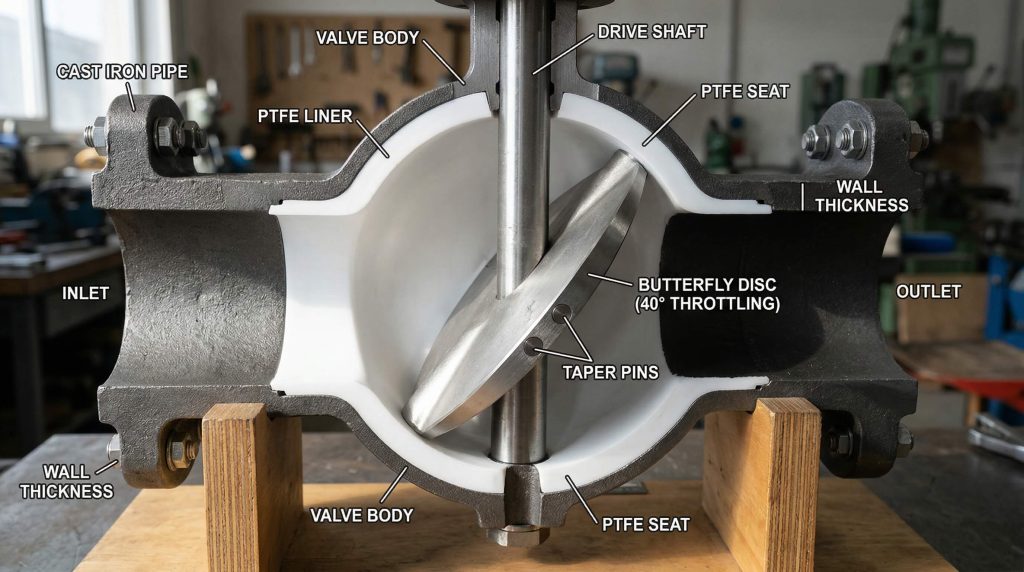
Disc geometry is the primary factor influencing turbulence and flow separation as the fluid passes through the valve body. Engineering the disc profile is critical because the butterfly valve loss coefficient is highly sensitive to the shape of the internal cavity. Thinner, more aerodynamic discs create smaller wakes and lower resistance.
Why do streamlined discs offer lower resistance?
A streamlined disc allows the fluid to rejoin smoothly on the downstream side, minimizing the energy-wasting eddies associated with blunt shapes. Believe it or not: you can achieve up to a 30% reduction in loss by choosing an optimized disc profile.
- Aerodynamic edges reduce turbulence.
- Smoother transitions prevent flow separation.
- Wake area is significantly minimized.
How do concentric vs. eccentric discs compare?
Concentric discs sit in the middle of the flow, while eccentric designs offset the shaft to reduce seat wear and improve sealing. Here is the kicker: you might trade a small amount of flow efficiency for the superior sealing performance of a triple-offset valve.
- Concentric discs have symmetric flow.
- Eccentric discs change the flow profile.
- Triple offset reduces friction during opening.
Key Takeaway: Disc selection is a balance between the need for low flow resistance and the requirement for a bubble-tight seal.
| Disc Type | Flow Efficiency | Primary Advantage |
|---|---|---|
| Concentric | High | Simple and cost-effective |
| Double Offset | Moderate | Reduced seat friction |
| Triple Offset | Variable | Zero-leakage performance |
Analyzing the disc’s impact on fluid dynamics helps you choose the right valve for either throttling or on-off service.
What causes high butterfly valve loss coefficient?
Factors such as internal scaling, debris, and improper installation can significantly increase the resistance beyond the manufacturer’s specifications. Several factors can unexpectedly inflate the butterfly valve loss coefficient, leading to significant pressure bottlenecks in your line. Even a small mismatch in pipe alignment can create huge turbulence.
Is internal scaling a major contributor?
As minerals or deposits build up on the valve disc and body, the surface roughness increases and the effective flow area shrinks. Think about it: you are paying for the energy lost to friction against a surface that should be smooth.
- Scaling increases surface friction.
- Reduced area raises flow velocity.
- Pressure drop increases exponentially.
How does valve-to-pipe diameter mismatch increase loss?
When the valve is smaller than the surrounding pipe, the sudden contraction and expansion of fluid create massive energy losses. But wait, there’s more: you must ensure the transition is gradual to prevent the formation of “dead zones” in the flow.
- Contraction loss occurs at the inlet.
- Expansion loss occurs at the outlet.
- Mismatched IDs cause localized turbulence.
Key Takeaway: Maintaining a clean and properly aligned flow path is just as important as the initial valve selection.
| Trigger Factor | Magnitude of Increase | Prevention Method |
|---|---|---|
| Scaling/Build-up | High | Regular chemical cleaning |
| Misalignment | Moderate | Use alignment pins/studs |
| Debris/Blockage | Extreme | Install upstream strainers |
Identifying these bottlenecks early allows you to perform targeted maintenance before the system efficiency reaches a critical low.
Is PN rating linked to butterfly valve loss coefficient?
Pressure ratings generally dictate the thickness of the valve walls and the robustness of the disc, which can subtly alter the internal flow path. While pressure ratings (PN) define safety limits, they also indirectly influence the butterfly valve loss coefficient through body wall thickness and flow path changes. High-pressure valves often require thicker discs that occupy more of the flow area.
Do high-pressure valves inherently have more resistance?
Because high-pressure discs must withstand greater forces, they are often bulkier, which can obstruct the flow more than a low-pressure counterpart. Look at it this way: you should verify the specific Zeta value for high-pressure applications rather than assuming standard values.
- Thicker discs increase blockage area.
- Robust seats may protrude into flow.
- Reinforced shafts add to the wake.
How does flange type affect the entry/exit loss?
The way the valve connects to the pipe—whether wafer, lug, or flanged—can create small gaps or steps that trigger turbulence. Think about it: you want a seamless transition from the pipe wall to the valve body to maintain laminar flow.
- Wafer types offer the shortest path.
- Flanged bodies provide stable alignment.
- Lug types allow for end-of-line service.
Key Takeaway: Always check if the structural requirements of a high PN rating will impact your required flow performance.
| PN Rating | Structural Impact | Flow Resistance Trend |
|---|---|---|
| PN10 / PN16 | Standard disc thickness | Lowest resistance |
| PN25 / PN40 | Thickened disc/stem | Moderate resistance |
| PN64+ | Heavy-duty internals | Highest resistance |
Balancing the safety of a higher pressure rating with the efficiency of a low-loss design is a hallmark of good engineering.
Can you reduce butterfly valve loss coefficient?
You can proactively lower the butterfly valve loss coefficient by selecting valves with high-performance internal coatings and optimized flow paths. Optimization often involves choosing specialized materials that minimize boundary layer friction. This ensures that the pneumatic actuator works less and the system stays cooler.
Would a PTFE lining decrease surface friction?
Polytetrafluoroethylene (PTFE) and other low-friction liners create a “non-stick” surface that allows fluid to slide through with minimal resistance. Believe it or not: you can significantly reduce the energy consumption of your system by simply upgrading the lining material.
- PTFE has a very low friction factor.
- Liners protect the body from scaling.
- Flow remains consistent over time.
Is periodic maintenance the key to stable flow?
Regularly checking the disc for pitting, corrosion, or debris ensures that the original flow characteristics of the valve are maintained. But wait, there’s more: you can extend the service life of your entire pneumatic system with a simple inspection schedule.
- Polishing the disc reduces roughness.
- Replacing worn seats prevents leaks.
- Cleaning prevents permanent scale build-up.
Key Takeaway: Strategic material choices and routine care are the most effective ways to keep flow resistance at a minimum.
| Strategy | Performance Gain | Complexity |
|---|---|---|
| Low-Friction Coating | 10–15% efficiency boost | Low |
| Disc Polishing | Reduced turbulence | Medium |
| Path Optimization | Minimized head loss | High |
Implementing these strategies during the procurement phase pays dividends in reduced energy bills and fewer system repairs.
How does opening angle change butterfly valve loss coefficient?
The resistance of a butterfly valve is not constant; it increases dramatically as the disc moves from the fully open position toward a closed state. It is well-documented that the butterfly valve loss coefficient varies exponentially as the pneumatic actuator moves the disc from 0° to 90°. This relationship is critical for applications involving throttling or flow control.
What is the resistance at 30% versus 100% open?
When a valve is only 30% open, the disc creates a massive obstruction, resulting in a Zeta value that is many times higher than when it is fully open. Think about it: you are using the valve as a deliberate energy absorber to control the flow rate.
- Full open (90°) has minimum Zeta.
- 30% open has very high resistance.
- The curve is non-linear and steep.
Is there a “sweet spot” for throttling control?
Most butterfly valves provide the best control and the most predictable resistance between the 30-degree and 70-degree opening angles. It gets better: you can program your pneumatic positioner to operate within this range to avoid instability and noise.
- 10–20° often leads to “hunting.”
- 30–70° provides linear control.
- 80–90° is best for full-flow efficiency.
Key Takeaway: Knowing the resistance curve is essential for tuning your control loops and preventing actuator jitter.
| Opening Angle | Relative Resistance | Flow Characteristics |
|---|---|---|
| 90° (Full Open) | 1.0x (Baseline) | Max flow / Low loss |
| 60° | ~3x to 5x | Moderate throttling |
| 30° | ~15x to 25x | High throttling / High loss |
Matching the valve’s characteristic curve to your process requirements ensures smooth automation and precise fluid delivery.
Which materials lower butterfly valve loss coefficient?
The material used for the disc and body determines the surface roughness, which is a direct variable in the calculation of friction-related losses. Material selection is not just about corrosion; the surface roughness of the material directly determines the butterfly valve loss coefficient. Highly polished stainless steel typically offers much lower resistance than rough cast iron.
Does stainless steel outperform ductile iron in flow?
Because stainless steel can be machined to a finer finish and is less prone to oxidation, it maintains a lower coefficient over the long term. Believe it or not: you might save enough in energy costs to justify the higher initial price of a stainless steel valve.
- SS316L has low surface roughness.
- Ductile iron can become pitted over time.
- Smooth surfaces inhibit biofilm growth.
How do elastomer liners affect the flow boundary layer?
Elastomers like EPDM or NBR provide excellent sealing but can have higher surface friction than metal unless they are specifically treated. Think about it: you must choose a liner that balances the need for a tight seal with the desire for low flow resistance.
- EPDM is durable but semi-rough.
- Viton offers chemical and flow stability.
- Treated liners reduce “drag” at the walls.
Key Takeaway: Material finish is a primary lever for engineers looking to squeeze every bit of efficiency out of their piping network.
| Material | Roughness ($\epsilon$) | Resistance Rating |
|---|---|---|
| Polished Stainless | Very Low | Excellent |
| PTFE Lined | Low | Very Good |
| Cast/Ductile Iron | Medium | Standard |
Selecting the right material combination prevents the valve from becoming a permanent drag on your system’s performance.
Where to find butterfly valve loss coefficient data?
Engineers should consult manufacturer data sheets, which provide Zeta values and Cv curves based on rigorous laboratory testing. Manufacturers like RUITO provide detailed technical sheets including the butterfly valve loss coefficient for every size and rating. Relying on generic data can lead to significant errors in system modeling.
How do you read a flow characteristic curve?
A flow curve plots the relationship between the valve’s opening angle and its flow capacity or resistance coefficient. Look at it this way: you can use these charts to determine if a specific valve size will meet your pressure drop requirements at peak flow.
- The X-axis usually shows the angle.
- The Y-axis shows Cv or Zeta.
- Logarithmic scales are common for Zeta.
Can you trust generic CFD data for your specific valve?
While Computational Fluid Dynamics (CFD) is a powerful tool, it should always be verified against physical flow test data from the actual manufacturer. The best part? You can request a full technical dossier from reputable suppliers to ensure your calculations are based on reality.
- CFD provides a visual flow model.
- Physical testing accounts for real-world friction.
- MTCs (Material Test Reports) confirm data.
Key Takeaway: Always use manufacturer-certified data to ensure your system design is both safe and efficient.
| Checklist for Data | Importance | Verification Method |
|---|---|---|
| Zeta vs. Angle Chart | Critical for control | Request Tech Data Sheet |
| Testing Standard | Ensures consistency | Check ISO/API compliance |
| Size-Specific Values | Prevents scaling errors | Verify for every DN size |
Accessing high-quality technical data is the final step in ensuring your pneumatic butterfly valve installation is optimized for success.
FAQ
Can I use the same loss coefficient for all pneumatic butterfly valves?
No, because the internal geometry, disc thickness, and seat design vary significantly between manufacturers and pressure ratings. Always consult the specific data sheet for your model.
What’s the best way to reduce pressure loss in a high-flow system?
Generally, you should select a valve with a streamlined disc profile and ensure the valve is fully open during peak demand. Using a valve with a polished stainless steel or PTFE-lined interior also helps.
How do I know if my valve’s loss coefficient is causing energy waste?
If you notice a significantly higher pressure drop across the valve than predicted, or if your pumps are drawing more current than expected, your valve may have high resistance due to scaling or improper sizing.
Can I calculate the loss coefficient for air the same way as for water?
Yes, but you must account for the compressibility of air if the pressure drop is more than 10% of the inlet pressure. For most low-pressure pneumatic systems, the standard Zeta formula works well.
How do I know if a valve is sized correctly for my flow resistance requirements?
It is essential to check the Zeta value at your maximum flow rate and ensure the resulting pressure drop does not exceed 5-10% of your total system pressure.
Conclusion
Understanding the butterfly valve loss coefficient is vital for any engineer looking to optimize pneumatic fluid control. Throughout this guide, we have explored how disc geometry, material selection, and opening angles combine to determine the energy efficiency of your system. By choosing high-performance valves with optimized Zeta values, you can prevent cavitation, reduce actuator wear, and lower your operational costs.
Are you ready to enhance your industrial performance with precision-engineered solutions? At RUITO, our mission is to deliver high-reliability, cost-effective valve and fluid control solutions that meet the most demanding global standards. Whether you are managing a municipal water project or a complex chemical processing plant, we provide the technical documentation and quality assurance you need to succeed. To receive a free technical consultation and explore our range of high-efficiency valves, contact us today.