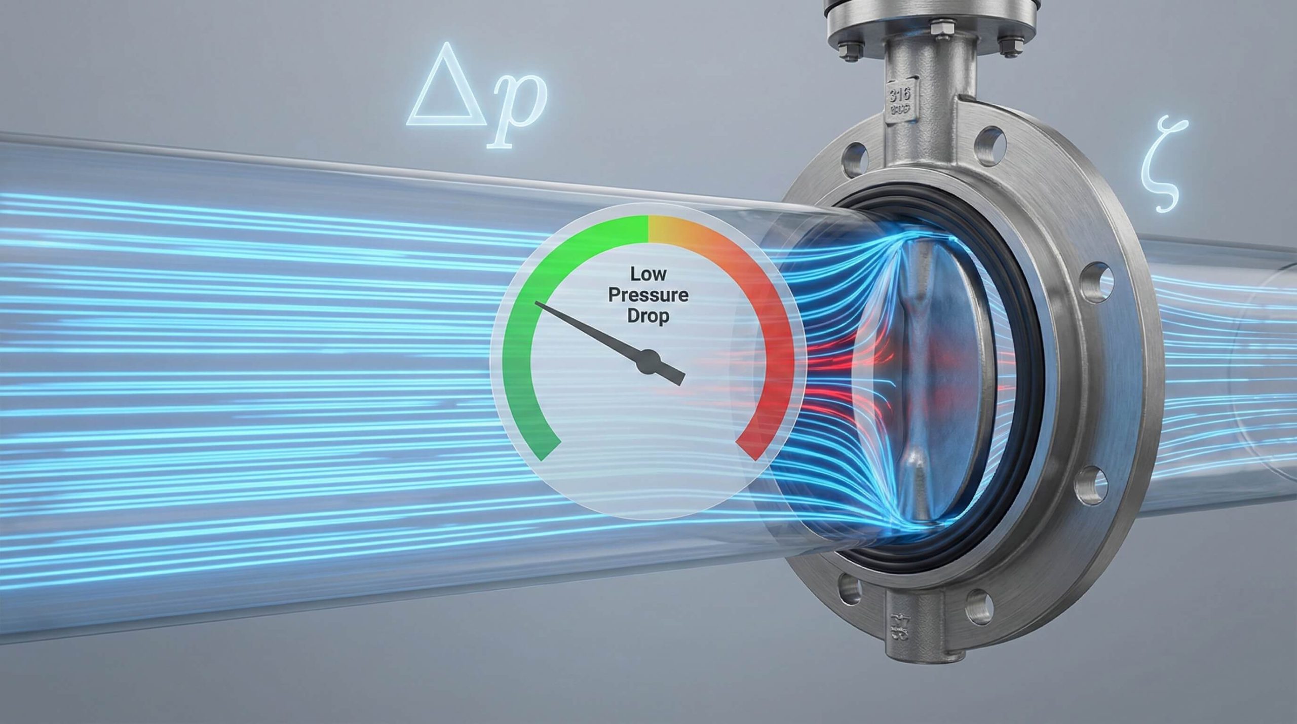
Pressure loss and the flow resistance coefficient in pneumatic butterfly valves are determined by the interaction between the valve’s internal geometry and the kinetic energy of the passing fluid. In complex industrial piping systems, maintaining efficiency is a constant struggle against the energy-draining effects of mechanical friction and turbulence. If you do not account for butterfly valve pressure loss, your system may suffer from excessive pump wear, high energy costs, and unstable flow control.
The reality is that every millibar of pressure lost represents wasted electricity and unnecessary strain on your pneumatic actuators. Choosing high-performance valves with optimized resistance coefficients ensures that your operation remains lean and reliable. By integrating precision-engineered solutions from experts like Ruito, you can effectively minimize these losses and maximize system throughput.
What causes butterfly valve pressure loss?
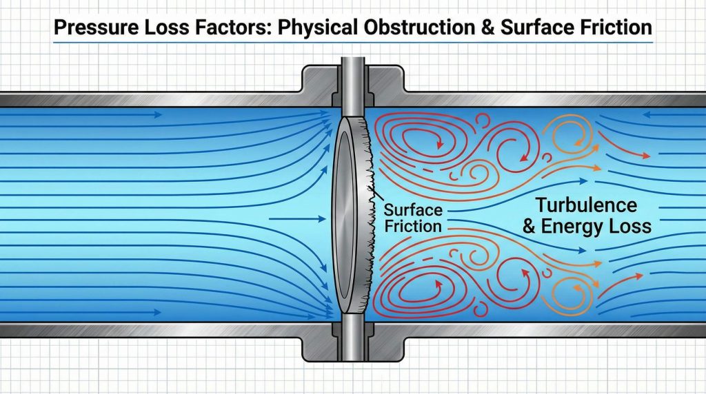
The primary causes of butterfly valve pressure loss are the physical obstruction of the disc and the surface friction generated as fluid moves across the valve internals. Even in a fully open position, the disc remains in the flow stream, creating a wake that dissipates energy.
Impact of Disc Geometry
The thickness and aerodynamic profile of the valve disc are fundamental to the resistance it creates. A streamlined disc allows fluid to pass with minimal separation, which keeps turbulence at a low level.
- Thicker discs create larger wakes.
- Aerofoil shapes improve pressure recovery.
- Beveled edges reduce entry resistance.
Surface Friction Dynamics
Think about it. The internal surface finish of both the valve body and the disc acts as a resistive force against high-velocity fluids.
Rougher surfaces increase the skin friction coefficient, leading to higher energy dissipation in the boundary layer of the flow. Reducing this roughness is essential for high-speed pneumatic applications where every bit of efficiency counts.
Key Takeaway
Total pressure loss is a combined result of the geometric obstruction provided by the disc and the frictional resistance of the valve’s internal surfaces.
| Factor | Effect on Loss | Mitigation Strategy |
|---|---|---|
| Disc Thickness | High | Use slim-profile discs |
| Surface Finish | Moderate | Specify polished internals |
| Flow Velocity | Critical | Optimize pipe and valve sizing |
This table demonstrates that while velocity is the most volatile variable, hardware choices like disc thickness significantly influence baseline resistance.
How to calculate butterfly valve pressure loss?
Calculating butterfly valve pressure loss involves applying the flow resistance coefficient ($\zeta$) to the kinetic energy of the fluid within the pipeline. This calculation allows engineers to predict the exact drop in pressure for any given flow rate.
Using the Resistance Formula
The standard mathematical model is $\Delta p = \zeta \cdot (\rho v^2 / 2)$, where pressure drop is proportional to the square of the velocity. This means that doubling your flow speed will quadruple the resulting pressure loss.
- Identify the fluid density ($\rho$).
- Measure the flow velocity ($v$).
- Select the $\zeta$ value for the specific valve model.
Understanding Kv and Cv
Here is the kicker. While $\zeta$ measures resistance, the $Kv$ and $Cv$ values measure the flow capacity of the valve at a specific pressure drop.
These values are inversely related to the resistance coefficient; therefore, a valve with a high $Kv$ rating will inherently provide lower pressure loss. Professional sizing tools typically use these coefficients to ensure the pneumatic system is not over-pressurized.
Key Takeaway
Mathematical modeling of pressure loss requires the integration of the dimensionless resistance coefficient with the physical properties of the working medium.
| Variable | Symbol | Application |
|---|---|---|
| Resistance Coefficient | $\zeta$ | Defining mechanical obstruction |
| Flow Coefficient | $Kv$ | Determining flow capacity |
| Pressure Drop | $\Delta p$ | Calculating system energy loss |
An accurate calculation ensures that the pneumatic actuator is paired with a valve that does not exceed the system’s energy budget.
Why does angle affect butterfly valve pressure loss?
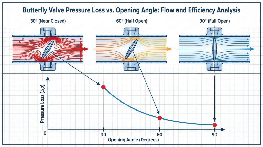
The opening angle affects pressure loss because it changes the projected area of the disc relative to the direction of the flow. As the disc rotates, the flow area expands or contracts, which dramatically alters the resistance coefficient.
Performance at 70-90 Degrees
At nearly full openings, the butterfly valve pressure loss is at its absolute minimum. The disc sits parallel to the flow, behaving more like a thin vane than an obstruction.
- Minimal wake formation.
- Highest flow capacity ($Kv$).
- Lowest energy consumption for pumps.
The Throttling Effect
The best part? You can use this non-linear relationship to precisely control flow, though resistance peaks sharply as the valve closes.
Below 60 degrees, the disc begins to act as a significant barrier, forcing the fluid into high-velocity streams through the remaining gaps. This creates intense turbulence and a rapid increase in the flow resistance coefficient, which is why butterfly valves are most efficient when operated at high angles.
Key Takeaway
Resistance increases exponentially as the opening angle decreases, making the 70-90 degree range the most efficient for high-volume transport.
| Angle | Resistance Level | Description |
|---|---|---|
| 90° | Very Low | Full open, minimal obstruction |
| 60° | Moderate | Standard regulation zone |
| 30° | Very High | Throttling with high energy loss |
Understanding these angular dynamics is crucial for programming pneumatic positioners to stay within efficient operating windows.
Does disc type change butterfly valve pressure loss?
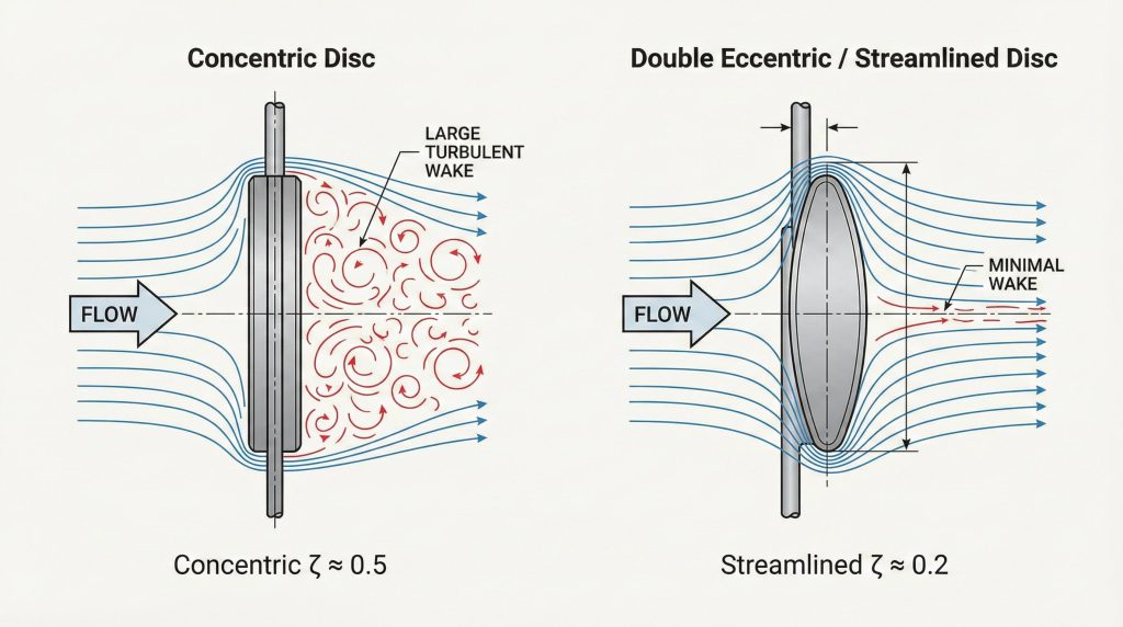
The specific disc type significantly changes butterfly valve pressure loss because different designs alter the way fluid separates and reattaches to the disc surface. Modern engineering offers several disc offsets to balance sealing requirements with flow efficiency.
Concentric vs. Eccentric Discs
Concentric discs are common in low-pressure systems but can create more turbulence because the stem passes directly through the center of the flow. Eccentric designs often allow for a more streamlined disc edge.
- Concentric: Simple and cost-effective.
- Double Offset: Reduces seat friction and improves flow.
- Triple Offset: Optimized for high-pressure sealing.
Hard Seal vs. Soft Seal
You might be wondering if the seal material itself affects flow. While the material is for sealing, the hardware required to hold it can change the disc’s profile.
Hard seal valves often feature more robust disc construction to handle high temperatures, which can slightly increase the resistance coefficient compared to slim soft-seal models. Choosing a high-performance disc design is the most effective way to manage these differences.
Key Takeaway
Selecting an eccentric or streamlined disc design can significantly lower the resistance coefficient compared to standard concentric models.
| Disc Design | Resistance Profile | Primary Advantage |
|---|---|---|
| Standard Concentric | Moderate | General purpose efficiency |
| Double Eccentric | Low-Moderate | Reduced wear and resistance |
| High-Performance | Low | Optimal for high-speed pneumatic control |
The data indicates that high-performance eccentric designs offer the best balance between mechanical longevity and low flow resistance.
How does size impact butterfly valve pressure loss?
Valve size impacts pressure loss by determining the velocity of the fluid as it passes through the valve body. For a constant flow rate, a smaller valve forces the fluid to move faster, which increases the resistance significantly.
Scaling and Flow Velocity
As the nominal diameter increases, the relative thickness of the disc compared to the pipe area often decreases. This trend generally leads to a lower resistance coefficient in larger valve sizes.
- DN50 valves have high relative obstruction.
- DN300+ valves offer superior flow paths.
- Proper sizing prevents sonic flow in pneumatic systems.
Impact of Pipe Reducers
But that’s not all. If you use a valve that is smaller than the pipe diameter, the required reducers will introduce their own pressure losses.
These transitions create turbulence before the fluid even reaches the valve disc. To maintain the lowest possible butterfly valve pressure loss, engineers usually attempt to match the valve size to the pipeline diameter whenever possible.
Key Takeaway
Upsizing a valve is one of the most effective ways to reduce pressure drop, as it lowers the fluid velocity and the relative disc obstruction.
| Valve Size | Velocity Effect | Resistance Tendency |
|---|---|---|
| Small (DN < 100) | Higher | More sensitive to disc shape |
| Large (DN > 250) | Lower | Inherently more efficient |
Choosing the correct size ensures that the pneumatic system operates within its designed pressure parameters without wasting energy.
What is the butterfly valve pressure loss at full open?
The butterfly valve pressure loss at full open represents the baseline resistance of the valve, which is usually at its lowest point. In this state, the flow resistance coefficient typically ranges between 0.2 and 0.5 for most industrial models.
Streamlining the Full Flow
In the fully open position, a high-quality pneumatic valve acts almost like a straight piece of pipe. However, the disc still occupies a small portion of the cross-sectional area.
- Streamlined discs minimize the low-pressure wake.
- Polished surfaces reduce skin friction.
- Precise alignment prevents entry turbulence.
Impact of Disc Alignment
What does this mean? If the pneumatic actuator is not properly calibrated to reach a full 90-degree opening, the valve will never reach its minimum resistance state.
Even a few degrees of misalignment can significantly increase the resistance coefficient. Ensuring that your pneumatic actuators are set to a true 90-degree stop is vital for achieving the advertised pressure loss specifications.
Key Takeaway
At a 100% opening, the pressure loss is minimized, provided the disc is perfectly aligned with the flow and features a streamlined profile.
| Component | Status at 100% | Impact |
|---|---|---|
| Disc Angle | 90° (Parallel) | Minimum resistance |
| Flow Area | Maximum | Highest $Kv$ |
| Turbulence | Minimal | Low energy dissipation |
This alignment is the single most important factor in maintaining the efficiency of an open pneumatic valve circuit.
Can media type influence butterfly valve pressure loss?
Media type influences pressure loss because the density, viscosity, and compressibility of the fluid interact differently with the valve disc. The butterfly valve pressure loss calculated for water will differ significantly from that of compressed air or oil.
Gas vs. Liquid Dynamics
Gases are compressible, meaning that as pressure drops across the valve, the gas expands and its velocity increases. This can create a cascading effect of higher resistance in the downstream section.
- Liquids: Incompressible, stable pressure drop.
- Gases: Compressible, velocity changes with $\Delta p$.
- Steam: Requires consideration of phase changes.
The Role of Viscosity
Look at it this way. Highly viscous fluids, like heavy oils, stick to the surfaces of the disc and body, creating a thicker boundary layer.
This increased skin friction raises the flow resistance coefficient. When working with non-standard media, you must adjust your calculations to account for these physical properties to avoid under-sizing your pneumatic system.
Key Takeaway
Accurate pressure loss prediction requires using the specific gravity and viscosity of the actual medium being transported through the valve.
| Medium Type | Resistance Characteristic | Consideration |
|---|---|---|
| Compressed Air | Low Friction | Compressibility factors |
| Process Water | Standard | Density and head loss |
| Viscous Oil | High Friction | Skin friction increases |
Selecting the right valve internals based on the medium is essential for long-term reliability and accurate flow control.
How to reduce butterfly valve pressure loss?
To reduce butterfly valve pressure loss, you must focus on optimizing both the hardware selection and the installation environment. Strategic choices during the design phase can lead to substantial energy savings over the life of the system.
Hardware Optimization Strategies
Selecting a valve with a high-performance, thin-disc design is the most direct way to lower the resistance coefficient. These discs are engineered to “slice” through the fluid.
- Use double or triple eccentric designs.
- Specify polished disc surfaces.
- Match the valve diameter to the pipe size.
Installation Best Practices
To make matters worse, many users ignore the impact of upstream piping. Turbulence from elbows or pumps can increase the effective resistance of the valve.
Installing the valve with at least 5 to 10 pipe diameters of straight run upstream allows the flow to stabilize. This ensures that the fluid enters the valve in a laminar state, which significantly reduces the energy lost to turbulence.
Key Takeaway
Optimization is achieved by combining streamlined valve designs with clean, straight piping configurations to ensure stable flow entry.
| Strategy | Action | Benefit |
|---|---|---|
| High-Flow Disc | Slim-profile selection | Lower mechanical $\zeta$ |
| Proper Sizing | Match DN to flow rate | Reduced fluid velocity |
| Piping Layout | Long straight runs | Reduced entry turbulence |
Implementing these strategies ensures that your pneumatic control system operates at peak efficiency with minimal pressure drop.
Is butterfly valve pressure loss critical in HVAC?
In large-scale HVAC systems, butterfly valve pressure loss is a critical metric because it determines the pumping power required to circulate water through a building. Excessive loss in these systems directly translates to higher utility bills.
Energy Efficiency in Pumping
HVAC systems often run 24/7, meaning that even a small reduction in the resistance coefficient can save thousands of dollars annually. Low-loss butterfly valves are the preferred choice for these high-volume applications.
- Reduces load on circulating pumps.
- Lowers system vibration and noise.
- Extends the lifespan of pneumatic actuators.
Balancing Flow in Networks
It gets better. Using pneumatic butterfly valves for balancing ensures that every branch of the HVAC network receives the correct amount of heating or cooling.
Predictable pressure loss curves allow for more accurate system balancing. When valves are sized correctly, they provide stable control without creating the massive pressure drops that lead to cavitation in cooling loops.
Key Takeaway
In HVAC and district heating, low-resistance valves are essential for minimizing operational costs and ensuring consistent thermal distribution.
| HVAC Component | Priority | Ideal Valve Role |
|---|---|---|
| Chiller Loops | High Volume | Low-loss transport |
| Air Handlers | Precision Control | Stable throttling |
| Heat Exchangers | Efficiency | Minimal energy dissipation |
Consistent monitoring of pressure drops in HVAC systems helps identify where energy is being wasted due to valve resistance.
How to measure butterfly valve pressure loss?
Measuring butterfly valve pressure loss requires the use of differential pressure sensors placed at strategic points in the pipeline. This empirical data is used to verify that the valve is performing according to its laboratory-tested flow resistance coefficient.
Differential Pressure Measurement
Simply put, you measure the static pressure at a point upstream and compare it to a point downstream where the flow has stabilized. The difference between these two values is your total loss.
- Use calibrated pressure transducers.
- Ensure sensors are placed away from elbows.
- Account for the height difference in vertical pipes.
Field Auditing Techniques
You might also use ultrasonic flow meters to determine the velocity of the fluid during these tests. By combining velocity and pressure data, you can calculate the real-world $\zeta$ value of your installation.
This allows you to detect issues like scale buildup or internal damage that might be increasing resistance over time. Regular audits ensure that your pneumatic valves continue to meet the efficiency standards required by your facility.
Key Takeaway
Field measurement is the only way to confirm that the installed piping configuration and valve condition are maintaining the expected resistance levels.
| Measurement Tool | Data Provided | Accuracy |
|---|---|---|
| Manometer | Differential Pressure | High |
| Ultrasonic Meter | Fluid Velocity | High |
| Pitot Tube | Localized Velocity | Moderate |
By tracking these metrics, you can maintain a high-performance fluid system that operates with maximum energy efficiency.
*
Frequently Asked Questions
Can I use a butterfly valve for high-pressure throttling?
Yes, but you must expect a high butterfly valve pressure loss and potential noise. For these applications, using a pneumatic positioner to maintain precise angles above 30 degrees is recommended to avoid cavitation.
What is the best way to choose a valve size?
You should choose a size where the normal flow velocity stays between 2–3 m/s for liquids. If the velocity is higher, the resistance coefficient will cause excessive pressure drop, so moving to a larger size is advised.
Does a pneumatic actuator affect the pressure loss?
The actuator itself does not create loss, but its ability to hold the disc at a perfect 90-degree angle is vital. Any failure to reach full opening will result in higher-than-expected flow resistance.
How does cavitation relate to pressure loss?
Cavitation occurs when the pressure drop across the valve is so great that the local pressure falls below the fluid’s vapor pressure. This usually happens at small opening angles where resistance is highest.
Is maintenance important for maintaining low pressure loss?
Yes, because scale or debris buildup on the disc increases surface roughness and effective thickness. Cleaning the valve internals during scheduled maintenance helps keep the resistance coefficient at its factory-rated level.
Conclusion: Optimizing Your Fluid System
Understanding the relationship between the flow resistance coefficient and butterfly valve pressure loss is the key to building a sustainable industrial network. By focusing on streamlined disc designs, precision pneumatic actuation, and proper system sizing, you can significantly reduce the energy overhead of your operations. Every component in your fluid system should contribute to a seamless, low-resistance flow path that protects your equipment and your bottom line.
Are you ready to enhance your system’s efficiency and reduce long-term energy costs? Our team is dedicated to providing high-performance pneumatic solutions tailored to your specific technical requirements. To ensure your system is running at peak performance, contact us today for a professional consultation and product recommendation.