The butterfly valve symbol is a standardized graphical icon used in technical drawings to represent a quarter-turn valve featuring a rotating disc. In industrial engineering, misidentifying a component on a complex schematic often leads to catastrophic procurement delays or system design flaws. By mastering the butterfly valve pid standards, you can ensure your project specifications are accurate, preventing costly on-site modifications and ensuring long-term operational safety.

What is the standard butterfly valve pid symbol?
The standard symbol for a butterfly valve consists of two non-filled triangles touching at their apex with a diagonal line across the center. This specific butterfly valve pid representation is unique because it is one of the few valve symbols that does not use solid-filled triangles.
How do you identify the geometry?
Here is the deal:
You will notice the triangles are oriented horizontally or vertically depending on the pipe flow direction. The diagonal line or small circle at the center represents the disc that rotates to regulate flow.
- Two open triangles (not filled).
- A center diagonal line or dot.
- Flow lines connecting at the triangle tips.
It gets better:
In most CAD libraries, you will find these symbols grouped by their connection types. Always verify the specific legend on your engineering package to confirm no custom variations are used.
Key Takeaway: Proper recognition of the basic geometry prevents you from confusing this component with globe or ball valves during initial system audits.
| Component | P&ID Representation | Operational Meaning |
|---|---|---|
| Valve Body | Two touching open triangles | Pressure containment unit |
| Rotating Disc | Diagonal line or dot | Flow control element |
| Stem/Handle | Perpendicular line | Manual or actuated interface |
Technical precision in the early design phase eliminates the risk of ordering linear-motion valves when a quarter-turn solution is required.
Why is the butterfly valve pid symbol unique?
The butterfly valve pid symbol is unique because it visually communicates the rotating nature of the disc rather than a sliding gate or rising stem. When compared to a ball valve, the butterfly icon emphasizes the narrow face-to-face dimension of the actual hardware.
Why not use a solid triangle?
You might be wondering:
Why distinguish it so clearly? The open triangles alert you to the fact that this valve has a high flow coefficient and a low pressure drop.
- Open triangles signify quarter-turn action.
- Diagonal lines denote the disc orientation.
- Simplified handles indicate manual levers.
Here is the truth:
Standardizing these symbols across your team ensures that everyone from the draftsman to the maintenance technician understands the mechanical limitations of the system.
Key Takeaway: Using the correct visual “weight” in your symbols helps you quickly scan large-scale diagrams for high-efficiency flow points.
| Feature | Butterfly Valve | Gate Valve |
|---|---|---|
| Symbol Fill | Open/Non-filled | Solid/Filled |
| Center Icon | Diagonal line | Vertical/Solid line |
| Core Logic | Rotational | Linear |
Analyzing symbol differences allows you to optimize system layouts for space-constrained environments where butterfly valves excel.
How to read a butterfly valve pid in schematics?
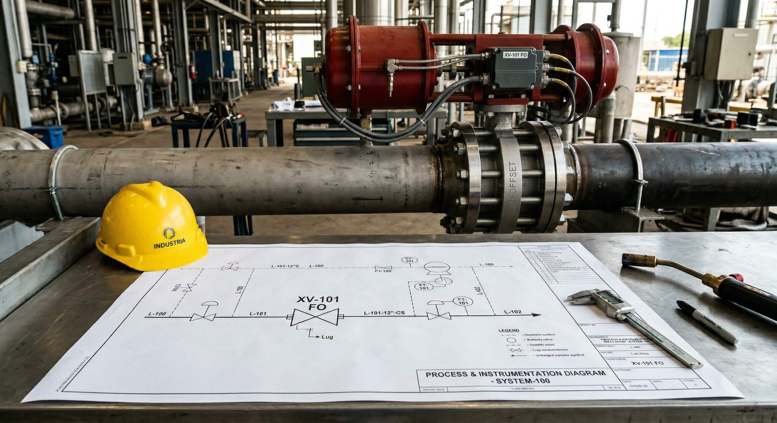
Reading a butterfly valve pid requires you to look for the tag number and the actuator type attached to the top of the symbol. You must identify whether the valve is currently in a “fail-open” or “fail-closed” position based on the arrows or letters provided.
What do the tag numbers mean?
It gets better:
The tag number (e.g., XV-101) links the symbol to a specific technical datasheet. You should always cross-reference this to ensure the material compatibility matches the process media.
- Check for FO (Fail Open) tags.
- Verify FC (Fail Closed) notations.
- Look for line size markers nearby.
The deal is this:
Without the accompanying text, a symbol is just a shape. You must integrate the graphical data with the technical schedule to ensure complete system visibility.
Key Takeaway: Reading the symbol in context with its tags allows you to perform safe isolation during maintenance procedures.
| Tag Element | Meaning | Application |
|---|---|---|
| XV / BV | Valve Identifier | Process control logic |
| FO / FC | Fail Position | Safety and emergency shutdown |
| NO / NC | Normal Position | Standard operating state |
Interrogating the fail-safe status on your diagrams is the most effective way to prevent environmental spills during power losses.
Which types of butterfly valve pid styles exist?
Multiple styles of the butterfly valve pid exist to distinguish between wafer, lug, and flanged connection methods. While the core symbol remains similar to a gate valve in layout, the peripheral lines indicate how the valve is physically bolted to the pipe.
How to show wafer vs lug?
Have you ever noticed:
The wafer style is often shown sandwiched between two flange lines, whereas the lug style may have small perpendicular marks. These marks represent the individual bolt holes used for dead-end service.
- Wafer: Floating between flanges.
- Lug: Bolt indicators on the body.
- Flanged: Solid double lines at tips.
You need to know:
Specifying the wrong connection style on the P&ID can lead to flange mismatches during the installation phase.
Key Takeaway: Identifying the connection style directly on the symbol ensures that your procurement team secures the correct hardware for dead-end or mid-line service.
| Style | P&ID Detail | Primary Benefit |
|---|---|---|
| Wafer | Single lines at tips | Lightweight, low cost |
| Lug | Perpendicular bolt ticks | Dead-end service capability |
| Flanged | Double parallel lines | High-pressure stability |
Choosing the right connection type is a strategic decision that impacts both your initial budget and your long-term maintenance accessibility.
Where do you place a butterfly valve pid on drawings?
Strategic placement of the butterfly valve pid symbol usually occurs on pump discharge lines or main process headers. You should place it where the operator needs clear visual confirmation of a flow isolation point.

Should it be near the pump?
Here is the deal:
Placing the symbol immediately after a pump discharge indicates it is being used for isolation or crude throttling. In P&IDs, this proximity helps you understand the sequence of shut-off in an emergency.
- On main process headers.
- At branch-off isolation points.
- In cooling water return lines.
It gets better:
Maintaining consistent spacing between the valve symbol and other instrumentation prevents the diagram from becoming cluttered and unreadable.
Key Takeaway: Strategic placement on the schematic ensures that maintenance teams can find physical isolation points without hunting through overlapping lines.
| Location | Purpose | Typical Pipe Size |
|---|---|---|
| Pump Discharge | Pump maintenance isolation | DN50 – DN600 |
| Tank Inlet | Level control/isolation | DN100 – DN1200 |
| Gravity Line | Flow throttling | DN200 – DN3000 |
Placing your symbols in logical operational groups reduces the cognitive load on operators who must manage the system in real-time.
How to show an actuated butterfly valve pid?
To represent an automated butterfly valve pid, you must add a “hat” or box above the center of the valve stem. This tells you if the valve is moved by a pneumatic diaphragm or an electric motor, similar to an automated check valve configuration.
How to identify the power source?
You might ask:
Is it pneumatic or electric? A half-circle indicates a pneumatic diaphragm, while a square with an “M” denotes an electric motor actuator.
- Square with “M” = Electric.
- Diaphragm (half-circle) = Pneumatic.
- Solenoid (box with “S”) = On/Off control.
The bottom line is:
Knowing the power source is critical for troubleshooting. If the valve isn’t moving, the symbol tells you whether to check the air compressor or the electrical cabinet.
Key Takeaway: Correct actuator symbols allow you to design the control logic and power distribution requirements before any equipment arrives on site.
| Actuator | Symbol Icon | Industry Use |
|---|---|---|
| Pneumatic | Diaphragm shape | Oil, Gas, Chemical |
| Electric | Square with “M” | HVAC, Water Treatment |
| Manual | Lever or Gear icon | Low-frequency isolation |
Actuation data is the bridge between the mechanical piping and the electronic control system, making it vital for system integration.
Does the butterfly valve pid change for offsets?
For high-performance applications, the butterfly valve pid may include specific notations for double or triple offset designs. You will often see a “3” or a “TOV” (Triple Offset Valve) label near the symbol to indicate specialized sealing requirements.
Why use offset symbols?
Here is the deal:
Standard symbols don’t always convey the sealing pressure. If you are handling high-temperature steam, you need the “TOV” notation to ensure a zero-leakage metal seat is installed.
- “3” or “TOV” for triple offset.
- “HP” for high-performance units.
- Double lines for high-pressure seats.
It gets better:
Adding these small details to your P&ID prevents the accidental installation of a standard rubber-seated valve in a corrosive chemical line.
Key Takeaway: Specialized notations for offsets protect your system from premature seal failure by ensuring the correct high-performance valve is specified.
| Offset Type | Symbol Marker | Best Application |
|---|---|---|
| Concentric | Standard symbol | Potable Water / HVAC |
| Double Offset | “DOV” or “HP” | Low-pressure Steam |
| Triple Offset | “TOV” or “3” | Petrochemical / High-temp |
Accurate offset labeling ensures that your safety-critical systems maintain zero-leakage performance under extreme conditions.
How do standards affect the butterfly valve pid?
Engineering standards like ANSI, ISA, and ISO dictate exactly how a butterfly valve pid should look to ensure global compatibility. If you are working on an international project, you must verify if the contact standard is ISA-5.1 or ISO 14617.
Are ANSI and ISO different?
You need to know:
While the core “two triangle” look is consistent, ISO standards tend to be more geometric, while ANSI/ISA focuses on functional clarity. Mixing these on one drawing causes confusion.
- ANSI/ISA: Common in North America.
- ISO: Standard for European projects.
- JIS: Specific to Japanese markets.
Here is the truth:
Choosing a single standard at the beginning of the project prevents the “lost in translation” errors that lead to failed safety audits.
Key Takeaway: Following a global standard ensures that your drawings are professional and legally compliant for international construction tenders.
| Standard Body | Primary Region | Visual Focus |
|---|---|---|
| ISA-5.1 | North America | Functional logic |
| ISO 14617 | Europe / Global | Geometric precision |
| DIN | Germany | Material specification |
Standardization is the bedrock of industrial safety, ensuring that a valve in Singapore is interpreted the same way as a valve in London.
Why is accuracy in your butterfly valve pid critical?
Accuracy in your butterfly valve pid documentation is the difference between a smooth plant startup and a million-dollar lawsuit. As a procurement professional, you rely on these symbols to bridge the gap between engineering theory and physical reality.
How does it prevent errors?
The deal is this:
When the symbol is correct, the bill of materials is correct. This leads to a streamlined supply chain where the right valves arrive at the right time.
- Eliminates procurement rework.
- Ensures 100% safety compliance.
- Reduces installation downtime.
It gets better:
Clear documentation makes your plant easier to maintain. Years after construction, a technician can look at your P&ID and know exactly what to do.
Key Takeaway: High-fidelity P&ID symbols are a long-term investment in the reliability and safety of your industrial infrastructure.
| Metric | Benefit of Accuracy | Risk of Error |
|---|---|---|
| Cost | No “wrong valve” returns | 15% – 25% budget overrun |
| Schedule | On-time commissioning | Weeks of project delay |
| Safety | 100% audit pass rate | Regulatory fines/penalties |
Precision in your drawings reflects the precision of your brand, establishing you as a leader in industrial engineering and design.
What are common butterfly valve pid layout errors?
The most common error in a butterfly valve pid layout is overcrowding the symbol with too many lines or overlapping it with tag numbers. This makes it nearly impossible for an operator to identify the quarter-turn functionality in an emergency.
How to avoid clutter?
You might ask:
How much space is enough? You should always maintain a clear zone around the valve symbol that is at least half the size of the symbol itself.
- Avoid overlapping tag numbers.
- Don’t hide the disc line.
- Ensure actuator “hats” don’t touch pipes.
The bottom line is:
A cluttered drawing is a dangerous drawing. If a technician cannot read the symbol, they might operate the wrong valve, leading to a system overpressure.
Key Takeaway: Prioritizing visual clarity in your layouts prevents human error during high-stress operational scenarios.
| Common Mistake | Consequence | Solution |
|---|---|---|
| Overlapping Tags | Identification failure | Use clear text leader lines |
| Filled Triangles | Confused with gate valve | Use open-triangle templates |
| Wrong Stem Angle | Incorrect handle clearance | Follow standard 90-degree rules |
Reviewing your layouts for clarity is the final step in producing a world-class engineering document that stands the test of time.
Frequently Asked Questions
Can I use a globe symbol for a butterfly valve pid?
No. You should never use a globe valve symbol (solid triangles) because it indicates a completely different mechanical operation and pressure drop profile.
What’s the best way to show a manual butterfly valve pid?
The best way is to use the standard open-triangle symbol with a simple “T-handle” or lever icon on top to signify manual operation.
How do I know if the butterfly valve pid is wafer style?
You can identify a wafer style if the symbol is drawn directly between two parallel lines representing the pipe flanges without additional bolt indicators.
Can I add seat material to a butterfly valve pid?
Usually, seat material is not on the symbol itself. You should include it in the “Valve Schedule” or use a specific letter code next to the tag number.
How do I show a bypass for a butterfly valve pid?
You should draw a smaller secondary line looping around the main valve symbol, containing its own smaller isolation valve (typically a globe or ball valve).
Conclusion
Mastering the butterfly valve symbol is an essential skill for any modern engineer or project manager involved in fluid control. This article has solved your problems by providing a clear roadmap through P&ID geometry, actuator identification, and placement logic.
At our core, we believe that precision in documentation is the first step toward excellence in manufacturing. Our vision is to provide the global industrial market with the most reliable, documentation-ready valve solutions available today.
Ready to secure the highest quality components for your next project? Contact us today for a technical consultation.