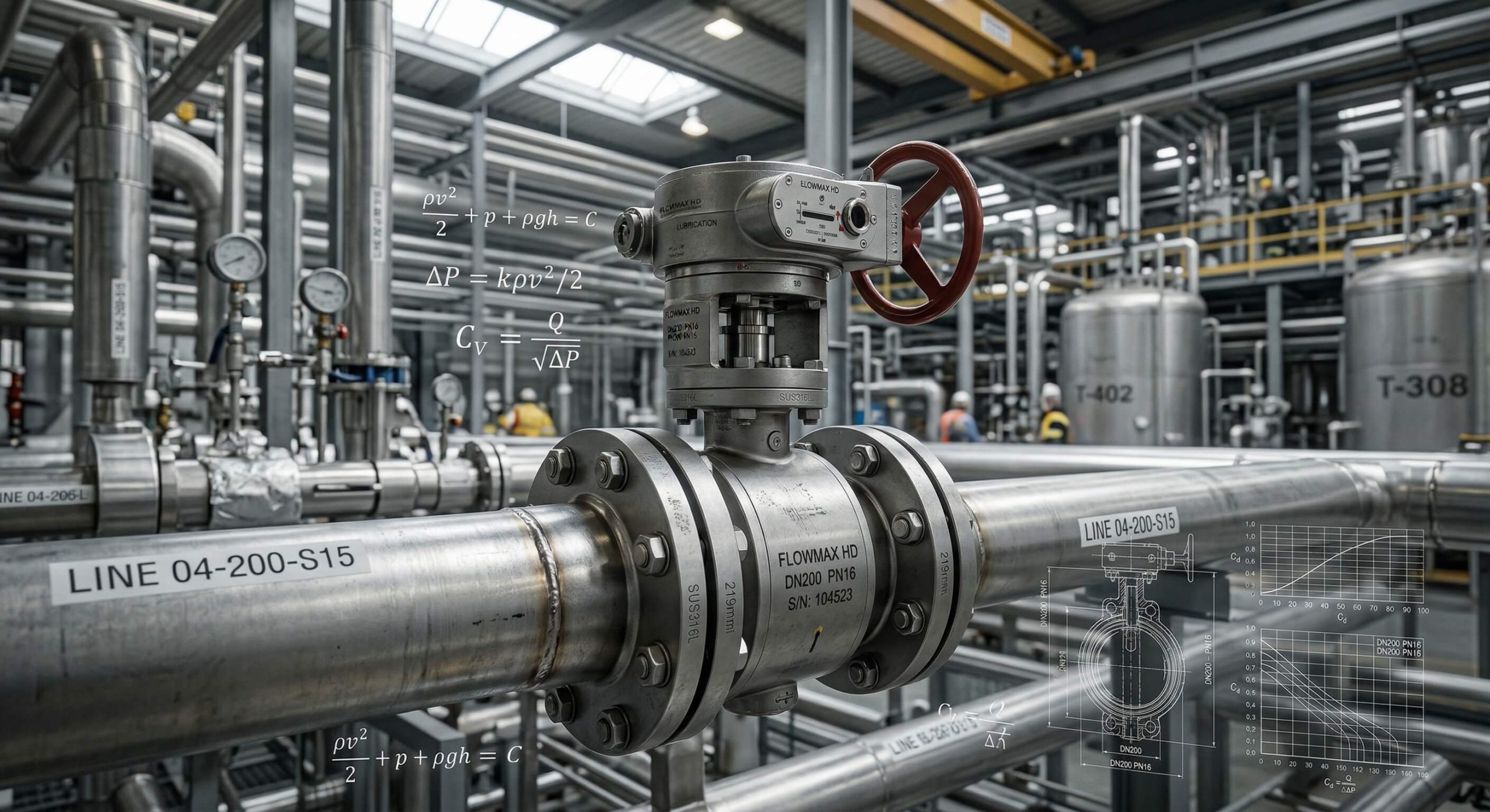
The valve flow coefficient represents exact water volumes passing per minute at one-pound pressure drops. Operators frequently face unpredictable fluid pressure fluctuations across aging networks. Such instability rapidly causes severe energy waste and expensive equipment failures. Selecting optimal flow through butterfly valve sizing based on coefficient analysis guarantees stable operations. This parameter allows engineers a reliable method for precise system calibration.
What defines Cv for flow through butterfly valve units?
The flow coefficient measures exact fluid capacities passing a structural restriction per minute accurately. Evaluating a flow through butterfly valve requires examining these specific metrics carefully during planning. Engineers use these numbers regularly during complex industrial pipeline setups worldwide. Factory teams depend upon accurate charts for safe liquid transmission.
How does this metric affect your workflow?
Accurate capacity numbers ensure highly stable fluid transmission networks across vast distances. This is where it gets interesting… precise measurements save immense capital annually.
- It reduces mechanical wear significantly across metal parts.
- It prevents dangerous pressure spikes during startup phases.
- It optimizes total energy consumption for massive pumps.
You will notice immediate performance improvements upon installation.
Why must you track these numbers?
Ignoring capacity parameters creates dangerous bottlenecks within active networks unexpectedly. Technicians face severe maintenance delays without proper numeric guidance continuously. Advanced planning prevents unnecessary financial losses during unexpected facility downtime.
Key Takeaway: Mastering basic coefficient data protects your pipeline against unexpected mechanical failures.
| Parameter | Unit | Application |
|---|---|---|
| Flow Rate | GPM | US Standard |
| Pressure Drop | PSI | Universal |
| Reference Fluid | Water | Baseline Test |
This chart illustrates fundamental baseline metrics required during initial component evaluation.
Why does flow through butterfly valve rely on accurate Cv?
Accurate coefficient data dictates correct component sizing for maximum operational efficiency daily. Unstable flow through butterfly valve mechanisms often causes severe structural damage rapidly. Operators depend upon reliable figures when designing modern chemical plants globally. Your safety protocols must mandate rigorous coefficient checks before installation.
How do wrong sizes impact systems?
Improperly sized components create immense friction against moving liquids constantly during operation. You might be wondering… what happens during extreme pressure surges unexpectedly?
- Cavitation destroys internal metal surfaces within weeks.
- Noise levels become hazardous quickly for nearby workers.
- Pump motors burn out prematurely due to stress.
You must match capacities precisely against projected network demands.
Can efficiency exist without proper data?
Operating blindly guarantees catastrophic mechanical breakdowns across aging facilities eventually. Maintenance teams spend countless hours fixing preventable pipeline ruptures monthly. Proactive math saves massive repair budgets over long operational decades.
Key Takeaway: Verifying capacity metrics eliminates costly downtime and prevents internal component destruction.
| Risk Factor | Consequence | Prevention Strategy |
|---|---|---|
| Cavitation | Pitting | Proper Sizing |
| High Velocity | Erosion | Velocity Control |
| Low Flow | Stagnation | Minimal Aperture |
This summary highlights severe risks avoided by utilizing accurate sizing information.
How do we calculate flow through butterfly valve Cv?
Professionals calculate this metric by dividing fluid volume by pressure loss square roots. Measuring flow through butterfly valve parameters demands rigorous mathematical discipline constantly during engineering. You can utilize specialized software tools for rapid evaluations today effortlessly. Complex algorithms process multiple variables instantly for optimal hardware sizing.
What formula governs these calculations?
The standard equation incorporates total volume alongside specific gravity figures perfectly. Ready for the good part? software automation simplifies this process entirely.
- Determine exact gallons per minute moving forward.
- Measure differential forces accurately across metal boundaries.
- Identify fluid specific gravity for heavy liquids.
You should verify every input twice before finalizing hardware purchases.
Are manual calculations still necessary today?
Automated systems provide incredible speed during complex industrial design phases naturally. However, understanding basic math helps technicians spot software errors immediately onsite. Relying entirely upon computers creates dangerous vulnerabilities without human oversight.
Key Takeaway: Mastering fundamental mathematical formulas empowers you during sudden network troubleshooting events.
| Variable | Definition | Unit Standard |
|---|---|---|
| Q | Fluid Volume | Gallons / Min |
| SG | Specific Gravity | Dimensionless |
| P | Pressure Drop | PSI |
This data breaks down core elements required for accurate mathematical modeling.
What factors change flow through butterfly valve rates?
Internal geometric shapes alongside fluid viscosity heavily influence total transmission capacities always. Assessing flow through butterfly valve behavior requires checking pipe diameters first carefully. Engineers must also evaluate surrounding ambient temperature conditions thoroughly before proceeding. Your calculations must account for seasonal temperature shifts across uninsulated pipes.
Does disc design alter volume output?
A thicker central disc creates greater resistance against incoming liquids naturally. What’s the real story? streamlined profiles maximize overall transmission speed consistently.
- Thinner discs reduce fluid drag across internal boundaries.
- Double offset designs minimize friction against rubber seats.
- Polished surfaces increase flow velocity past metal barriers.
You should specify internal finishes carefully for heavy industrial applications.
How does fluid thickness affect movement?
Heavy oils move significantly slower than pure water under identical conditions normally. Operators must adjust baseline calculations when handling viscous petrochemicals daily onsite. Modifying standard formulas prevents dangerous pressure buildups within enclosed systems.
Key Takeaway: Analyzing physical variables guarantees optimal material selection for specific chemical environments.
| Factor | Impact Level | Mitigation Approach |
|---|---|---|
| Viscosity | High | Heat Tracing |
| Disc Profile | Medium | Streamlined Design |
| Pipe Size | High | Correct Sizing |
This comparison shows how physical elements directly alter internal transmission characteristics.
How does angle alter flow through butterfly valve metrics?
Changing internal disc angles directly modifies available pathways for moving fluids completely. Modulating a flow through butterfly valve creates varying resistance levels instantly upon demand. Technicians utilize specific opening degrees for precise volume control daily. Small positional adjustments yield massive changes within high-velocity transmission lines.
Why are partially open states tricky?
Fluid velocities become highly erratic near closed disc positions constantly during operation. But here is the kicker… middle angles provide optimal regulation capabilities.
- Ten degrees limits movement severely creating high pressure.
- Forty degrees offers moderate control for stable transmission.
- Ninety degrees allows maximum capacity with minimal drag.
You must avoid operating near zero for prolonged industrial periods.
Does the coefficient increase linearly?
Capacity values curve exponentially as internal pathways expand toward full capacity quickly. Engineers consult specialized charts because straight math fails here completely. Reference guides map exact performance curves for every single angle.
Key Takeaway: Referencing specific angle charts prevents inaccurate volume predictions during automated modulation.
| Angle Degree | Relative Capacity | Flow Characteristic |
|---|---|---|
| 20 Degrees | Very Low | High Resistance |
| 50 Degrees | Moderate | Good Control |
| 90 Degrees | Maximum | Free Passage |
This table illustrates exponential capacity increases as internal pathways widen fully.
Is Kv different for flow through butterfly valve designs?
Kv represents metric transmission capacity while Cv denotes imperial measurement standards internationally. Comparing flow through butterfly valve specifications requires converting these figures accurately always. European manufacturers utilize cubic meters instead of gallons routinely across factories. Global supply chains demand strict adherence regarding regional mathematical conventions.
How do you convert these numbers?
Multiplying metric values by a constant factor yields accurate imperial equivalents effortlessly. This is where it gets interesting… global projects demand bilingual engineering mastery.
- One Kv equals 1.15 Cv for standard conversions.
- Metric systems use bar pressure for calculations.
- Imperial setups utilize pound force across American networks.
You must verify regional measurement standards before importing foreign hardware.
Does the unit matter during installation?
Mixing metric and imperial specifications causes catastrophic mismatches across global sites eventually. Planners double-check origin documentation before authorizing final component purchases always. Standardized units prevent massive confusion during emergency field repair operations.
Key Takeaway: Standardizing measurement units prevents expensive procurement errors during international construction projects.
| Metric | Region | Base Volume |
|---|---|---|
| Kv | Europe | Cubic Meters |
| Cv | USA | US Gallons |
| Av | Asia | Square Meters |
This summary clarifies regional standard variations utilized across international engineering projects.
How do you size a flow through butterfly valve correctly?
Proper sizing involves matching maximum expected volume against known coefficient ratings carefully. Evaluating flow through butterfly valve requirements protects against premature mechanical degradation completely. Designers analyze minimum and maximum operating conditions simultaneously for safety. Peak demand scenarios dictate absolute maximum hardware dimensions across facilities.
What steps guarantee accurate component selection?
Calculating worst-case scenarios provides safety margins for unpredictable industrial environments constantly. You might be wondering… how large is too large practically?
- Oversized units create poor control at low volumes.
- Undersized components cause massive friction during peak demand.
- Matched sizes ensure smooth operations across all phases.
You should target mid-range operating angles for standard daily usage.
Are safety margins strictly necessary?
Unexpected pressure surges destroy perfectly matched systems lacking adequate buffer zones instantly. Engineers add ten percent capacity buffers for sudden emergency events regularly. Extra capacity handles temporary operational spikes without requiring system shutdowns.
Key Takeaway: Balancing precise calculations with sensible safety margins ensures long-term pipeline reliability.
| Sizing Error | Symptom | Long Term Effect |
|---|---|---|
| Too Large | Poor Control | Valve Hunting |
| Too Small | High Velocity | Rapid Erosion |
| Perfect Fit | Smooth Flow | Long Lifespan |
This matrix highlights negative consequences caused by improper initial component dimensioning.
What risks harm flow through butterfly valve operations?
Excessive velocity forces rapidly erode metallic seating materials causing internal leaks permanently. Monitoring flow through butterfly valve performance prevents sudden catastrophic plant shutdowns efficiently. Airborne debris frequently damages soft rubber sealing components permanently over time. Preventive maintenance schedules must include mandatory coefficient checks every year.
How does cavitation destroy internal parts?
Vapor bubbles collapse violently against metal walls under high-pressure conditions frequently. Ready for the good part? specialized trims eliminate this destructive phenomenon entirely.
- Implosions chip away solid steel over several months.
- Vibrations loosen structural connecting bolts causing external leaks.
- Noise levels indicate immediate danger requiring quick action.
You must install anti-cavitation features proactively for high-stress industrial applications.
Can incorrect numbers cause pipeline ruptures?
Underestimated pressure forces overwhelm physical material limits leading toward massive explosions sometimes. Operators face extreme safety liabilities when ignoring specified mathematical boundaries intentionally. Rigorous testing protocols expose hidden flaws before full commercial deployment.
Key Takeaway: Prioritizing accurate mathematical modeling mitigates severe physical dangers across manufacturing facilities.
| Threat | Cause | Visible Sign |
|---|---|---|
| Cavitation | Pressure Drop | Popping Noise |
| Erosion | High Velocity | Worn Edges |
| Leakage | Seat Damage | Puddle Formation |
This chart catalogs physical threats created by ignoring accurate mathematical boundaries.
Do disc types change flow through butterfly valve Cv?
Eccentric disc geometries minimize seating friction while moderately reducing total capacity structurally. Designing flow through butterfly valve networks requires analyzing specific offset configurations thoroughly. High-performance triple offset units offer tight seals alongside adequate transmission rates. Complex internal shapes alter fluid dynamics compared against flat profile designs.
Why use double offset designs today?
Shifting the rotational axis away from centerlines reduces constant seat rubbing effectively. What’s the real story? longevity often outweighs maximum volume needs completely.
- Concentric discs rub constantly causing rapid rubber degradation.
- Double offsets rub only briefly during closing sequences.
- Triple offsets eliminate rubbing entirely for metal seats.
You gain incredible durability with offsets despite minor capacity reductions.
Are concentric units completely obsolete now?
Low-pressure water systems still utilize basic concentric models for cheap control widely. However, demanding chemical applications require advanced eccentric geometries for absolute safety. Zero-leakage requirements mandate specialized metal seating technologies across modern plants.
Key Takeaway: Selecting appropriate disc geometries balances required transmission rates against extreme physical durability.
| Disc Type | Friction Level | Flow Capacity |
|---|---|---|
| Concentric | High | Maximum |
| Double Offset | Medium | High |
| Triple Offset | Zero | Moderate |
This breakdown evaluates distinct performance trade-offs associated with different disc configurations.
Where are flow through butterfly valve Cv charts found?
Manufacturers publish detailed coefficient matrices within their official technical product catalogs universally. Sourcing reliable flow through butterfly valve data ensures compliant industrial installations quickly. Reputable engineering portals maintain updated databases for immediate digital access globally. Technical support teams provide specific performance curves upon formal customer request.
How reliable is third-party data online?
Generic websites often display outdated figures leading toward dangerous sizing mistakes inevitably. But here is the kicker… original factory documents remain supreme always.
- Factory catalogs guarantee exact accuracy for specific models.
- Engineering software updates data automatically preventing mathematical errors.
- Third-party blogs risk serious errors causing pipeline failures.
You must verify sources before ordering expensive heavy metal equipment.
Can you request custom flow testing?
Specialized laboratory facilities perform empirical testing for highly unique industrial applications routinely. Engineers receive certified documentation proving exact performance under specific conditions officially. Accredited testing ensures full compliance regarding stringent international safety regulations.
Key Takeaway: Relying upon certified manufacturer documentation guarantees safe and fully compliant network designs.
| Source Type | Accuracy | Reliability |
|---|---|---|
| Factory Manual | 100% | Supreme |
| Sizing Software | 99% | Excellent |
| Generic Blog | Variable | Poor |
This reference guide categorizes data sources based upon verified technical accuracy.
Conclusion
This article resolved complex sizing calculations by clarifying baseline coefficient metrics entirely. We provide robust manufacturing solutions for demanding industrial pipeline applications worldwide. Achieving flawless transmission efficiency defines our primary engineering vision moving forward. Please contact us today for personalized sizing recommendations.
FAQ
Q1: Can I calculate pipeline capacity without software?
Yes, manual math works perfectly. You can utilize standard formulas involving volume and specific gravity directly.
Q2: What’s the best disc design for maximum volume?
Concentric configurations remain superior here. These basic designs feature minimal internal obstructions compared against complex offsets.
Q3: How do I know if my unit is oversized?
Erratic regulation signifies obvious oversizing. A massive unit struggles with maintaining stable control at low transmission rates.
Q4: Can I use metric data for US pipelines?
No, direct usage causes failures. You must convert European metric figures into imperial standards using specific multipliers.
Q5: What’s the best way to prevent dangerous cavitation?
Proper sizing eliminates this threat. Matching your exact capacity requirements against manufacturer charts prevents severe pressure drops.