
The pressure drop coefficient K is a dimensionless value that defines the hydraulic resistance and energy loss of a fluid as it navigates through piping components like valves and fittings. Designing a piping system without precise resistance data leads to catastrophic failures or massive energy waste. If you ignore the butterfly valve k factor, your pumps may fail prematurely, or cavitation could destroy your piping infrastructure within months. This guide provides the technical breakdown of K-coefficients needed to ensure hydraulic balance and long-term system reliability.
What is the butterfly valve k factor definition?
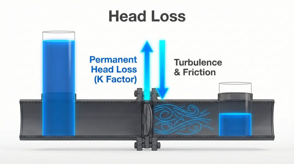
The butterfly valve k factor, also known as the resistance coefficient, represents the permanent head loss caused by a valve singularity. It is a fixed ratio that compares the pressure energy lost to the kinetic energy of the moving fluid. Unlike the flow coefficient (Cv), which measures volume, the K factor focuses on the friction-induced resistance of the hardware.
What does the K coefficient represent?
The K coefficient acts as a multiplier for velocity head. It accounts for the turbulence and internal friction generated as the fluid is forced around the valve disc.
Here is the deal:
This value is independent of the fluid’s specific gravity in turbulent flow. It allows engineers to simplify complex fluid dynamics into a single manageable number for system-wide calculations.
Is K different from the flow coefficient Cv?
Yes, while both measure performance, they are inversely related. A higher K factor indicates higher resistance, whereas a higher Cv indicates higher flow capacity.
- K measures energy loss.
- Cv measures flow rate per pressure drop.
- High-performance systems aim for low K and high Cv.
| Component Detail | Metric Type | Application |
|---|---|---|
| K Factor | Dimensionless | Resistance/Head Loss |
| Cv / Kv | Flow Rate | Sizing/Capacity |
| Fluid Regime | Turbulent | Re > 4000 |
The K factor is a dimensionless metric of resistance, essential for calculating local energy losses in turbulent flow regimes.
Why is the butterfly valve k factor vital for sizing?
Accurate piping design requires knowing exactly how much energy a pump must provide to overcome the butterfly valve k factor and other system resistances. If you underestimate the resistance, your pump will underperform, leading to insufficient flow at the terminal points. Conversely, overestimating leads to wasted energy and excessive wear.
How does K influence pump selection?
Engineers sum the K values of all fittings to determine the total system head. This total head directly dictates the pump’s required horsepower and operating curve.
The bottom line is:
If the system resistance is incorrectly calculated, the pump will operate away from its Best Efficiency Point (BEP). This results in higher vibration, heat, and shortened mechanical seal life.
Why does head loss impact operational costs?
Higher resistance requires more electrical power to move the same volume of fluid. Over the lifespan of a municipal or industrial plant, even a small reduction in the K factor can save thousands in utility costs.
- Optimal pump sizing prevents motor burnout.
- Accurate K values ensure system “authority” during throttling.
- Energy efficiency is maximized when resistance is minimized.
| System Impact | Result of Underestimation | Result of Overestimation |
|---|---|---|
| Flow Rate | Below Target | Above Target (Wasted) |
| Pump Stress | High (End of Curve) | High (Dead-heading) |
| Energy Cost | Inefficient | Optimized |
Precise K factor application prevents both under-design and over-engineering, ensuring cost-effective pump operation.
How does opening angle affect butterfly valve k factor?
The opening angle is the single most critical variable affecting the butterfly valve k factor. As a butterfly valve disc rotates from 0° (fully open) to 90° (fully closed), the flow path changes from a streamlined passage to a total obstruction. The resistance does not increase linearly; it follows an exponential curve.
Does resistance increase at partial openings?
The resistance coefficient increases dramatically as the valve closes. For example, a valve at 5° closed may have a K of 0.24, but at 60° closed, that value can jump to 118.
Look at it this way:
Small changes in disc position create massive shifts in hydraulic resistance. This sensitivity is why precise control is required for throttling applications.
What happens at the 30-70% stable range?
In this control range, the K factor allows for predictable throttling without extreme turbulence. Manufacturers provide detailed charts showing the K value at every 10-degree increment to help engineers manage this sensitivity.
- Fully Open (0°): Minimum resistance (K ≈ 0.2–0.5).
- Partially Closed (40°): High resistance (K ≈ 10.8).
- Throttling Range: Exponential increase in head loss.
| Opening Angle | K Factor (Typical) | Resistance Level |
|---|---|---|
| 0° (Fully Open) | 0.20 – 0.50 | Very Low |
| 20° Closed | 1.54 | Moderate |
| 40° Closed | 10.8 | High |
| 60° Closed | 118.0 | Extreme |
The K factor is highly sensitive to disc position, requiring precise angle-to-resistance charts for throttling applications.
Can design impact the butterfly valve k factor range?
The physical configuration of the hardware determines how the butterfly valve k factor behaves under load. A concentric design with a thick disc will always have a higher K factor than a high-performance butterfly valve k factor design with a streamlined profile. The internal geometry is effectively the “fingerprint” of the valve’s resistance.
Do concentric vs eccentric designs differ?
Eccentric or offset valves move the disc out of the flow path more efficiently. This often results in a lower fully-open K factor and better recovery of pressure downstream.
Think about it:
Every millimeter of disc thickness in the flow stream contributes to the wake. High-performance offsets minimize this wake, maximizing your energy efficiency.
How does seat material affect loss?
While the disc is the primary obstruction, the seat transition can create minor turbulence. Smooth, PTFE-lined seats typically offer slightly better flow characteristics than rougher, unlined surfaces.
- Concentric valves: High symmetry, moderate resistance.
- Offset valves: Improved flow path, lower open K values.
- Streamlined discs: Reduced turbulence at the trailing edge.
| Design Type | Disc Profile | Relative K Factor |
|---|---|---|
| Concentric | Standard | Moderate |
| Double Offset | Streamlined | Low |
| Triple Offset | High Precision | Lowest |
Valve architecture determines the baseline resistance; high-performance designs are engineered specifically to lower the open K factor.
How to calculate ΔP using butterfly valve k factor?
To find the actual pressure drop, you must apply the butterfly valve k factor within the standard Darcy-Weisbach derivative. The formula is simple, but the accuracy depends entirely on using the correct velocity and density values for your specific media. Failing to account for these variables will result in significant calculation errors.
What is the standard pressure drop formula?
The pressure drop (ΔP) is calculated as: ΔP = K * (ρV² / 2). Here, ρ is the fluid density and V is the average velocity in the pipe.
Here is the thing:
Because the velocity is squared, doubling your flow rate quadruples your pressure drop. This makes the accuracy of the K factor even more critical in high-velocity systems.
Should you sum multiple K coefficients?
Yes, in a complex line, the total pressure loss is the sum of all individual K values. You must add the values for valves, elbows, and tees, then multiply by the dynamic pressure.
- Identify the K value for the valve at its operating angle.
- Determine fluid density (kg/m³) and velocity (m/s).
- Apply the formula to find loss in Pascals (Pa).
- Sum all “singularities” in the pipe section.
| Variable | Description | Unit |
|---|---|---|
| ΔP | Pressure Drop | Pa |
| ρ | Fluid Density | kg/m³ |
| V | Flow Velocity | m/s |
| K | Resistance Coeff | Dimensionless |
Pressure drop calculation is a direct function of the K factor and the square of the fluid velocity.
Is the butterfly valve k factor valid for all flows?
It is a common mistake to assume the butterfly valve k factor is a universal constant for all fluid states. In fact, K factors are generally only accurate for fully developed turbulent flow. This typically occurs when the Reynolds number (Re) exceeds 4,000 in your piping system.
Why is the Reynolds number critical?
The Reynolds number defines the ratio of inertial forces to viscous forces. In turbulent flow, the K factor stabilizes and becomes independent of the Reynolds number.
The reality is:
If your system is operating in the transition zone, your pressure drop predictions will be inconsistent. You must ensure your velocity is high enough to maintain turbulence.
Does K change in laminar flow regimes?
In laminar flow (Re < 2,000), viscous forces dominate, and standard K factor charts no longer apply. Different coefficients or the “Equivalent Length” method are preferred for high-viscosity fluids.
- Re > 4,000: Turbulent (K is stable).
- 2,000 < Re < 4,000: Transition (K is unpredictable).
- Re < 2,000: Laminar (K is Reynolds-dependent).
| Flow Regime | Reynolds Number | K Factor Validity |
|---|---|---|
| Laminar | < 2,000 | Low |
| Transition | 2,000 – 4,000 | Moderate |
| Turbulent | > 4,000 | High |
Standard K factor tables are designed for turbulent industrial water and process lines; they may fail in high-viscosity applications.
Where to find reliable butterfly valve k factor data?
Relying on generic textbooks for the butterfly valve k factor can lead to sizing errors. According to our about-us engineering team, manufacturer-specific data is always superior. This is because it accounts for the unique disc thickness and body casting of that specific model.
Are manufacturer charts more accurate?
Yes, manufacturers perform flow tests in controlled laboratories to generate K vs. Angle curves. This data reflects the actual performance of the valve you are purchasing.
Believe it or not:
A 5% difference in disc geometry between two brands can lead to a 15% difference in K factor. Engineering without OEM data is essentially guessing.
How to interpret published K tables?
Standard tables usually provide K for “Standard Radius” or “Standard Open” configurations. Always check if the data includes downstream recovery pipe effects, as this can alter the perceived loss.
- Technical Datasheets: Best source for specific models.
- Engineering Handbooks: Good for preliminary estimates.
- CFD Simulations: Used for non-standard or custom designs.
| Data Source | Accuracy | Best Use Case |
|---|---|---|
| OEM Datasheet | 99% | Final Design |
| Perry’s Handbook | 85% | Pre-Project |
| Generic Online Table | 70% | Rough Estimate |
Always prioritize OEM-certified charts over generic industry tables to ensure the highest calculation accuracy.
How does size change the butterfly valve k factor?
The relationship between valve size and the butterfly valve k factor is not always perfectly proportional. While geometric similarity is a goal, smaller valves often have a higher K factor than larger valves. This happens because the disc takes up a larger relative percentage of the flow area.
Is geometric similarity maintained?
In theory, similarity exists, but the shaft-to-bore ratio is often larger in small valves. This is necessary to maintain structural integrity under high torque loads.
But there is more:
The boundary layer effects in smaller pipes are more pronounced. This increases the relative friction, leading to a higher resistance coefficient.
Do larger DN ratings have lower K values?
Generally, as the pipe diameter (DN) increases, the K factor for a fully open valve slightly decreases. The relative disc obstruction becomes less significant compared to the total flow area.
- DN50–DN150: Higher relative resistance.
- DN300–DN1200: Lower relative resistance.
- Scaled Models: Require verified flow testing for accuracy.
| Valve Size (DN) | Obstruction Ratio | Relative K Value |
|---|---|---|
| Small (DN50) | High | Higher |
| Medium (DN200) | Moderate | Standard |
| Large (DN600) | Low | Lower |
Don’t assume a DN50 valve and a DN500 valve have identical K factors; always verify the coefficient for the specific nominal diameter.
Does disk shape optimize butterfly valve k factor?
Advanced fluid dynamics has allowed manufacturers to “sculpt” the disc to minimize the butterfly valve k factor. Even a 2mm reduction in disc thickness or a change in the edge profile can reduce the K factor by 15-20%. This is critical in high-velocity systems where every Pascal of pressure counts.
Can streamlined disks reduce turbulence?
Streamlined discs allow the fluid to rejoin with less eddy formation at the trailing edge. This reduces the wake size and lowers the pressure drop across the singularity.
Simply put:
A thinner, profiled disc functions like an airfoil. It guides the fluid rather than simply obstructing it, resulting in superior hydraulic efficiency.
Do materials impact the coefficient?
High-strength alloys allow for thinner disc cross-sections while maintaining the same pressure rating. This geometric advantage directly translates to a lower K factor.
- Fish-tail discs: Designed for improved control and lower K.
- Cambered profiles: Optimized for specific flow directions.
- Polished surfaces: Minimize skin friction in high-purity lines.
| Optimization | Method | Benefit |
|---|---|---|
| Streamlining | Tapered Edges | Lower Wake Loss |
| Thinning | High-Strength Alloys | Larger Flow Area |
| Coating | Low-Friction Finish | Reduced Skin Drag |
Optimized disc geometry is a primary method for reducing K factors and increasing overall system efficiency.
What are common butterfly valve k factor pitfalls?
Even experienced engineers occasionally stumble on the nuances of the butterfly valve k factor. A calculation is only as good as its inputs. Using a “fully open” K factor for a valve that will spend 90% of its life at 30° open is a recipe for system failure.
Is K often confused with the Cv value?
Many confuse the two or use them interchangeably in simulation software. Remember: K is a dimensionless coefficient for head loss, while Cv is for flow capacity.
In fact:
Using the wrong input in a simulator will yield junk results. This often leads to pumps that are sized for a resistance that doesn’t exist.
Are legacy charts always reliable?
Older charts may not account for modern high-performance designs. Using a 1970s gate valve K factor for a modern butterfly valve will result in significant over-design.
- Mistake 1: Using “Fully Open” K for throttling valves.
- Mistake 2: Ignoring fluid density changes in gas systems.
- Mistake 3: Failing to account for upstream pipe turbulence.
| Common Pitfall | Impact | Prevention |
|---|---|---|
| Wrong Opening Angle | Inaccurate ΔP | Use Angle-Specific K |
| Density Oversights | Massive Math Error | Update ρ for Temperature |
| Mixed Units | Sizing Failure | Verify Metric vs Imperial |
Avoid “rule of thumb” coefficients; use specific, modern K factor data for the actual operating conditions of your system.
Conclusion
Understanding the resistance coefficient is essential for any engineer tasked with designing efficient, reliable industrial piping. By correctly applying the K factor, you ensure that pumps are sized perfectly, energy is conserved, and the system operates within its intended hydraulic parameters. For detailed technical charts or specific sizing assistance for your next project, contact us today.
Frequently Asked Questions
- Can I use the K factor for gas flow?
Yes, but with caution. You must use the average density and velocity across the valve; for significant pressure drops, break the system into smaller segments for better accuracy. - What’s the best way to verify a manufacturer’s K factor?
Request certified data. The best method is to ask for certified flow test reports (ISO 5208 or API 598) or CFD simulation data for that specific valve model. - How do I know if my system is in turbulent flow?
Check the Reynolds number. If your calculation (Re = ρVD/μ) yields a result above 4,000, your flow is turbulent, and standard K factor tables are valid. - Can I calculate K if I only have the Cv value?
Yes, it is possible. K is approximately equal to891 * (d^4 / Cv^2), wheredis the internal pipe diameter in inches, though manufacturer data remains the gold standard. - What is the typical K value for a fully open valve?
It is relatively low. For most industrial butterfly valves, the fully open K factor ranges between 0.2 and 0.5, which is comparable to a standard gate valve.