In complex industrial piping projects, a single misinterpreted icon on a Piping and Instrumentation Diagram (P&ID) can lead to catastrophic installation errors. If you confuse a high-performance rotary valve with a standard isolation valve, the entire flow control logic of your system fails.
Imagine the cost of downtime when a shipment of flanged components arrives at a site designed for wafer-thin connections, all because the schematic was ambiguous. Misreading the symbol of butterfly valve isn’t just a technical oversight; it is a safety risk that compromises pressure ratings and fail-safe protocols in critical environments.
This guide provides an expert-level breakdown of every standardized icon used in modern engineering to ensure your project documentation is flawless. By mastering these visual cues, you can guarantee that your installations are precise and your procurement processes remain efficient.

What is the standard symbol of butterfly valve?
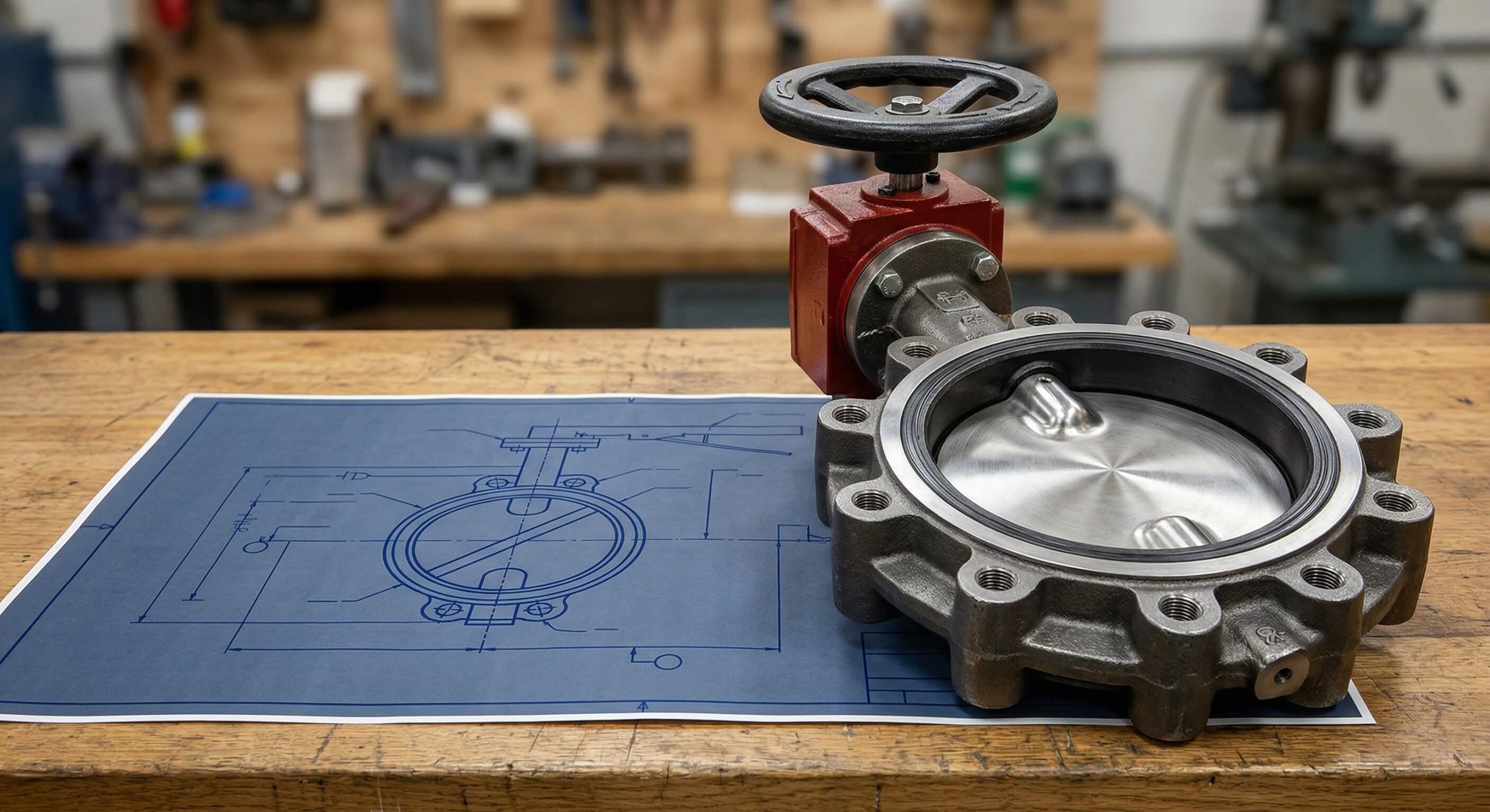
The fundamental symbol of butterfly valve consists of a circle bisected by a diagonal or straight line representing the rotating disc. You will find that the circle represents the valve body, while the internal line symbolizes the mechanism that controls fluid flow.
The Core Graphic Representation
Standard drawings use this simplified geometry to denote a quarter-turn valve that is capable of both on/off and throttling services. It is the most recognizable icon for rotary motion in pipeline schematics.
- Circle: Represents the external valve body.
- Internal Line: Represents the disc or “butterfly.”
- Pipeline Interfaces: Shown as lines entering and exiting the circle.
Think about it. Without this clear distinction, you might mistake a rotary valve for a linear globe valve.
Open vs. Closed Position Indicators
In a P&ID, the orientation of the center line within the symbol of butterfly valve is critical for understanding operational states. An open valve shows the line parallel to the pipeline, whereas a closed valve shows it perpendicular.
- Parallel Line: Indicates a 90-degree rotation allowing full flow.
- Perpendicular Line: Indicates the disc is blocking the passage.
- Throttling Angle: Occasionally shown at a 45-degree angle for modulation.
Here is the deal. Most modern CAD software will default to the “closed” position to emphasize safety boundaries.
Key Takeaway: The visual “disc” inside the circle is the primary identifier that distinguishes this from other rotary valves in professional drafting.
| Component | Visual Description | Functional Meaning |
|---|---|---|
| Body | Circular boundary | External housing |
| Disc | Diagonal/Straight bisector | Flow control element |
| Stem | Vertical line to actuator | Mechanical connection |
Why is the P&ID symbol of butterfly valve critical?
Using a standardized symbol of butterfly valve allows teams in different countries to interpret the same design without language barriers. This consistency is essential for large-scale EPC (Engineering, Procurement, and Construction) projects where errors lead to massive budget overruns.
Ensuring Global Engineering Clarity
Standardization prevents confusion between different types of rotary equipment, such as a ball valve versus a butterfly valve. You can ensure that every technician on-site understands the torque requirements and flow characteristics just by looking at the drawing.
- ANSI/ISA-5.1: Common in North American oil and gas.
- ISO 10628: The global standard for chemical processing.
- Industry Legends: Every P&ID should include a lead sheet for symbol verification.
But wait, there’s more. Clear symbols also streamline the safety audit process for high-pressure systems.
Avoiding Installation Mismatches
When you use a specific symbol of butterfly valve, you provide clear instructions to the procurement team regarding the valve’s physical profile. This ensures that the spacing between pipe flanges is calculated correctly before the first bolt is tightened.
- Space Constraints: Butterfly valves are significantly thinner than gate valves.
- Weight Considerations: Proper symbols alert engineers to support requirements.
- Flow Direction: Some high-performance models require specific orientation.
The best part? Accurate symbols reduce the “Requests for Information” (RFIs) that typically delay project handovers.
Key Takeaway: Standardized symbols act as a universal language that protects your project’s schedule, budget, and operational safety.
| Risk Factor | Impact of Poor Symbolism | Mitigation Strategy |
|---|---|---|
| Procurement | Buying the wrong valve type | Use ANSI/ISO standards |
| Safety | Misinterpreting fail-safe states | Add “FC” or “FO” notations |
| Installation | Flange misalignment | Specify wafer/lug icons |
Does the ISO 10628 symbol of butterfly valve differ?
The ISO 10628 symbol of butterfly valve provides a more functional, block-style representation compared to traditional North American versions. It often focuses on the “diamond” or circular disc blocking the pipe line rather than the detailed instrumentation tags.
Form 1 vs. Form 2 ISO Variations
ISO standards offer different levels of detail depending on whether you are creating a Process Flow Diagram (PFD) or a detailed P&ID. Form 1 is generally simpler, while Form 2 adds layers for complex instrumentation.
- Form 1: A simple circle in the pipe path.
- Form 2: Includes a center line and connection dots.
- Functionality: Prioritizes process logic over physical appearance.
You might be wondering. Why use ISO if ANSI is more detailed?
European vs. International Drafting Rules
While ISO is the “global” language, many European projects lean heavily on ISO 14617 for specific component details. You will find that these symbols are better suited for high-level diagrams where flow paths are the priority.
- Simplicity: Reduced line counts for cleaner schematics.
- Consistency: Aligned with global petrochemical standards.
- Adaptability: Easily paired with international actuator symbols.
Here is the deal. ISO symbols are often preferred for their readability in very dense, complex plant layouts.
Key Takeaway: ISO symbols prioritize functional logic and simplicity, making them ideal for high-level process documentation in international markets.
| Standard | Core Focus | Preferred Region |
|---|---|---|
| ISO 10628 | Functional process flow | Europe and Asia |
| ISO 14617 | Specific component parts | International projects |
| ISO 3511-3 | Instrumentation/Actuators | Global chemical plants |
How to read the ANSI symbol of butterfly valve?
The ANSI/ISA-5.1 symbol of butterfly valve is the gold standard for North American oil, gas, and power projects. You will notice it excels at showing how the valve integrates with control loops and electronic sensors.
Instrumentation and Control Integration
ANSI symbols typically feature a vertical stem leading to an actuator circle or box, which contains specific tags like “TV” or “LV.” This tells you exactly which control loop the valve belongs to within the plant’s automation system.
- Tag Numbers: Unique identifiers for every valve.
- Signal Lines: Dashed or solid lines showing electrical/pneumatic input.
- Modulation: Shows if the valve is used for precise throttling.
Think about it. This level of detail is what keeps complex refineries running smoothly without manual intervention.
Fail-Safe and Actuator Notations
A critical part of the ANSI symbol of butterfly valve is the fail-safe indicator, often written as “FC” for Fail Closed. This ensures that in a power loss scenario, you know exactly what the valve will do to protect the system.
- FC (Fail Closed): Spring forces the valve shut.
- FO (Fail Open): Spring forces the valve to open.
- FL (Fail Last): Valve stays in its current position.
The best part? These notations are standard across all ANSI-compliant industries, reducing the risk of operator error.
Key Takeaway: ANSI symbols provide deep integration data, making them the preferred choice for automated and instrumentation-heavy facilities.
| Notation | Meaning | Safety Implication |
|---|---|---|
| FC | Fail Closed | Prevents downstream leaks |
| FO | Fail Open | Prevents pressure buildup |
| FL | Fail Last / Locked | Maintains current flow state |
What is the wafer symbol of butterfly valve?
The wafer-style symbol of butterfly valve is often depicted as a “bowtie”—two triangles touching at a single point inside a circle. You should recognize this as the narrow profile valve designed to be sandwiched between pipe flanges.

Recognizing the Bowtie Graphic
This specific symbol of butterfly valve is the only one where full triangles are not used, distinguishing it from gate or globe valves. The thin connection point highlights that the valve does not have its own flanges.
- Thin Profile: Represented by the narrow intersection.
- No Flange Lines: Indicates it shares bolts with the pipes.
- Compact Design: Used for space-saving installations.
Here is the deal. If you see the bowtie, you know you need long bolts that pass through both flanges and the valve.
Identifying Mid-Line Placement
Unlike other valves, the wafer symbol must be perfectly centered on the line to indicate its non-flanged nature. You will see that it sits directly between the two pipe ends without any additional gaps or squares.
- Line Alignment: The valve body is centered on the pipe axis.
- Bolt Path: Implied by the lack of vertical flange markers.
- Weight: Usually indicated as the lightest rotary option.
But wait, there’s more. This symbol is crucial for maintenance teams who need to know if they can remove a pipe section easily.
Key Takeaway: The “bowtie” variation specifically identifies the wafer-style body, which is essential for determining bolt length and flange spacing.
| Body Style | Symbol Indicator | Installation Method |
|---|---|---|
| Wafer | Simple Bowtie / Narrow | Sandwiched between flanges |
| Lug | Bowtie with corner dots | Bolted directly to flanges |
| Flanged | Circle with vertical lines | Uses two sets of bolts |
Is there a unique lug symbol of butterfly valve?
To denote a lugged connection, the symbol of butterfly valve may include small circles or dots at the corners of the bowtie. You will use this to identify valves with threaded bolt holes that allow for dead-end service.
The “Dot” or Circle Corner Method
The addition of corner dots signifies that the valve is a lug type, meaning it has ears that match the flange hole pattern. This allows you to bolt the valve directly to one side of the pipeline.
- Threaded Ears: Represented by the small corner circles.
- Bolt Alignment: Shows the valve is fixed to the pipe.
- Versatility: Can be used as a terminal valve at pipe ends.
Think about it. This tiny detail changes the entire maintenance capability of the system.
Suitability for End-of-Line Service
Lug symbols are critical for maintenance teams because they indicate the valve can remain in place while downstream piping is removed. You can safely isolate a section of the plant without needing a second valve for protection.
- Dead-End Service: Safe for use at the end of a line.
- Maintenance: Allows pipe removal on one side only.
- Security: Provides a more robust connection than wafer types.
The best part? Lugged valves prevent the “slips” that can occur with wafer types during installation.
Key Takeaway: Lug symbols use corner dots to indicate threaded connections, signifying that the valve is suitable for end-of-line maintenance.
| Connection | Symbol Detail | Best Application |
|---|---|---|
| Lug | Corner Dots/Circles | End-of-line service |
| Wafer | Plain Bowtie | Mid-line flow control |
| Threaded | Small hollow circles | Low-pressure small pipes |
How to identify the pneumatic symbol of butterfly valve?
An automated symbol of butterfly valve adds an actuator icon, usually a semi-circle or a box, on top of the valve stem. For pneumatic systems, you will find the letter “P” placed inside this icon to indicate it is driven by compressed air.
Actuator Overlays and Lettering
The actuator symbol is attached to the basic valve icon to show how it is operated remotely. You can quickly tell the difference between pneumatic, electric, and hydraulic systems by looking at the letter code.
- “P”: Pneumatic actuator (air-driven).
- “E”: Electric actuator (motor-driven).
- “H”: Hydraulic actuator (fluid-driven).
Here is the deal. Pneumatic systems are the most common in butterfly applications due to their high speed and reliability.
Spring-Return vs. Double-Acting
You can tell these apart by looking for arrows on the symbol of butterfly valve actuator. An arrow pointing toward the valve indicates a spring-return mechanism designed to close the valve if air pressure is lost.
- Single Arrow: Indicates spring-return (fail-safe).
- Double Line: Indicates double-acting (air required for both directions).
- Positioner: Often labeled “POS” for precise modulating control.
You might be wondering. Why does the direction of the arrow matter?
Key Takeaway: Pneumatic symbols combine the basic valve icon with a “P” coded actuator, using arrows to define fail-safe behaviors.
| Actuator Type | Symbol Code | Power Source |
|---|---|---|
| Pneumatic | Circle/Box with “P” | Compressed Air |
| Electric | Circle/Box with “E” | Electricity |
| Hydraulic | Circle/Box with “H” | Pressurized Oil |
What is the manual symbol of butterfly valve?
The manual symbol of butterfly valve is the most common icon you will encounter in non-automated systems. It features a T-bar, a diagonal lever, or a small handwheel at the end of the stem.
Handwheel and Lever Indicators
Lever handles are usually represented by a single diagonal line, which signifies a quick quarter-turn operation. For larger valves, you will see a handwheel represented by a small “O” or circle icon at the top of the stem.
- Diagonal Line: Indicates a handle/lever.
- Handwheel: Represented by a small circle.
- T-Bar: Used for simpler manual overrides.
Think about it. The choice between a lever and a handwheel is usually determined by the valve’s size and torque requirements.
Gearbox Notations for Large Valves
For larger diameters where a lever is insufficient, a “Worm Gear” symbol is added to the symbol of butterfly valve. This is usually shown as a small box with a diagonal line, indicating a reduction gearbox for easier manual turning.
- Worm Gear: A box between the valve and handwheel.
- Mechanical Advantage: Essential for valves over 8 inches.
- Slow Operation: Gearboxes prevent water hammer by slowing the closure.
The best part? These symbols help you plan for the physical clearance needed to turn the handle or wheel.
Key Takeaway: Manual symbols use levers or handwheels to denote human operation, with gearbox icons added for high-torque applications.
| Handle Type | Symbol Graphic | Valve Size Range |
|---|---|---|
| Lever | Diagonal line | Small (2″ to 6″) |
| Handwheel | Small circle | Medium (8″ to 12″) |
| Gearbox | Box + Handwheel | Large (14″+) |
Does the flanged symbol of butterfly valve vary?
The flanged symbol of butterfly valve uses heavy vertical lines on both sides of the valve body circle. You should interpret this as a sign that the valve has its own integral flanges and requires two independent sets of bolts.
Double Flange Visual Markers
These markers distinguish the flanged valve from wafer or lug types that “share” the pipeline’s bolts. You will find this symbol used most often in high-pressure or large-diameter water treatment and industrial systems.
- Vertical Lines: Represent the valve’s own flange faces.
- Bolt Sets: Indicates a more permanent, heavy-duty installation.
- Rigidity: Flanged valves offer the best structural support.
Here is the deal. Flanged connections are standard for valves exceeding 24 inches in diameter.
Pipe Gap Conventions
In many 3D isometric drawings, the symbol of butterfly valve for flanged types shows a distinct gap between the valve and the pipe. This gap represents the space required for the gasket and the flange interface during assembly.
- Visual Gap: Shows the valve is a separate, removable unit.
- Maintenance: Indicates the valve can be dropped out without cutting pipe.
- Seal Type: Often paired with notes about gasket materials.
But wait, there’s more. These gaps help the installation team verify they have the correct take-out dimensions.
Key Takeaway: Flanged symbols use thick vertical lines to indicate integral flanges, prioritizing structural integrity and ease of maintenance.
| Parameter | Flanged Symbol | Wafer Symbol |
|---|---|---|
| Line Width | Heavy vertical markers | No vertical markers |
| Bolt Count | Two sets required | One long set required |
| Pressure | High pressure capable | Low to medium pressure |
How to choose the right symbol of butterfly valve?
Selecting the correct symbol of butterfly valve depends entirely on your project’s regional standards and technical requirements. You must always refer to the “Lead Sheet” or “Legend” of your specific P&ID before finalizing your procurement.
Matching Standards to Project Geography
The best part? You can avoid massive delays by using ANSI for North American projects and ISO for European or Asian developments. Mixing these standards on a single project leads to confusion among contractors and safety inspectors.
- USA/Canada: Use ANSI/ISA-5.1.
- Europe/Global: Use ISO 10628.
- Company Standards: Always check for internal proprietary icons.
You might be wondering. What if my software doesn’t have the exact symbol?
Verification via Legend Sheets
Always verify the symbol of butterfly valve against the actual Bill of Materials (BOM). Even within international standards, minor company-specific tweaks can occur, so the legend sheet is your final source of truth.
- Lead Sheet: The “dictionary” for your specific project.
- BOM Check: Ensure the symbol matches the part number.
- Drafting Review: Have a senior engineer sign off on the schematics.
Think about it. A five-minute check of the legend sheet can save five days of re-work in the field.
Key Takeaway: Selecting the right symbol requires aligning with regional standards and verifying every icon against the project’s master legend sheet.
| Step | Action | Objective |
|---|---|---|
| 1 | Identify Region | Choose ANSI or ISO |
| 2 | Consult Legend | Confirm specific icons |
| 3 | Cross-Check BOM | Ensure hardware matches |
Frequently Asked Questions
- Can I use a custom symbol of butterfly valve?
While possible, it is highly discouraged because third-party inspectors and contractors may not understand your internal language. Always stick to ISO or ANSI standards to ensure global readability. - What’s the best standard for symbol of butterfly valve?
For instrumentation-heavy projects like oil and gas, ANSI/ISA-5.1 is superior. For general chemical process flows, ISO 10628 is the industry favorite for its simplicity. - How do I show a fail-safe symbol of butterfly valve?
Use an arrow pointing toward the valve for “Fail Closed” (FC) and an arrow pointing away from the valve for “Fail Open” (FO) on the actuator symbol. - Where can I find the symbol of butterfly valve in CAD?
Most CAD software, such as AutoCAD Plant 3D or SolidWorks, includes built-in libraries for both ISO and ANSI standards. - Are P&ID and ISO symbol of butterfly valve the same?
Not exactly. P&ID refers to the type of drawing (Piping and Instrumentation Diagram), while ISO is the standard that defines how the symbols on that drawing should look.
Conclusion
Selecting the correct industrial components is a high-stakes decision that impacts your facility’s safety and profitability. At RUITO, we specialize in manufacturing precision-engineered valves that meet the most rigorous international standards, including ISO, CE, and DNV. Our expert team is ready to provide you with technical drawings, full documentation, and custom engineering solutions tailored to your specific project needs. Contact us today to receive a comprehensive technical consultation and discover how we can optimize your fluid control systems for maximum efficiency.