An industrial butterfly valve is a quarter-turn rotational motion valve designed to stop, regulate, and start fluid flow within a piping system. Maintaining efficient fluid control in large-scale industrial operations often becomes a logistical nightmare when leaks and pressure drops occur. These failures lead to costly downtime, safety risks, and operational inefficiencies that significantly drain your corporate resources. This comprehensive guide serves as your roadmap for technical selection, utilizing a detailed diagram of butterfly valve to ensure you choose the perfect fit for your application.
What are the parts in a diagram of butterfly valve?
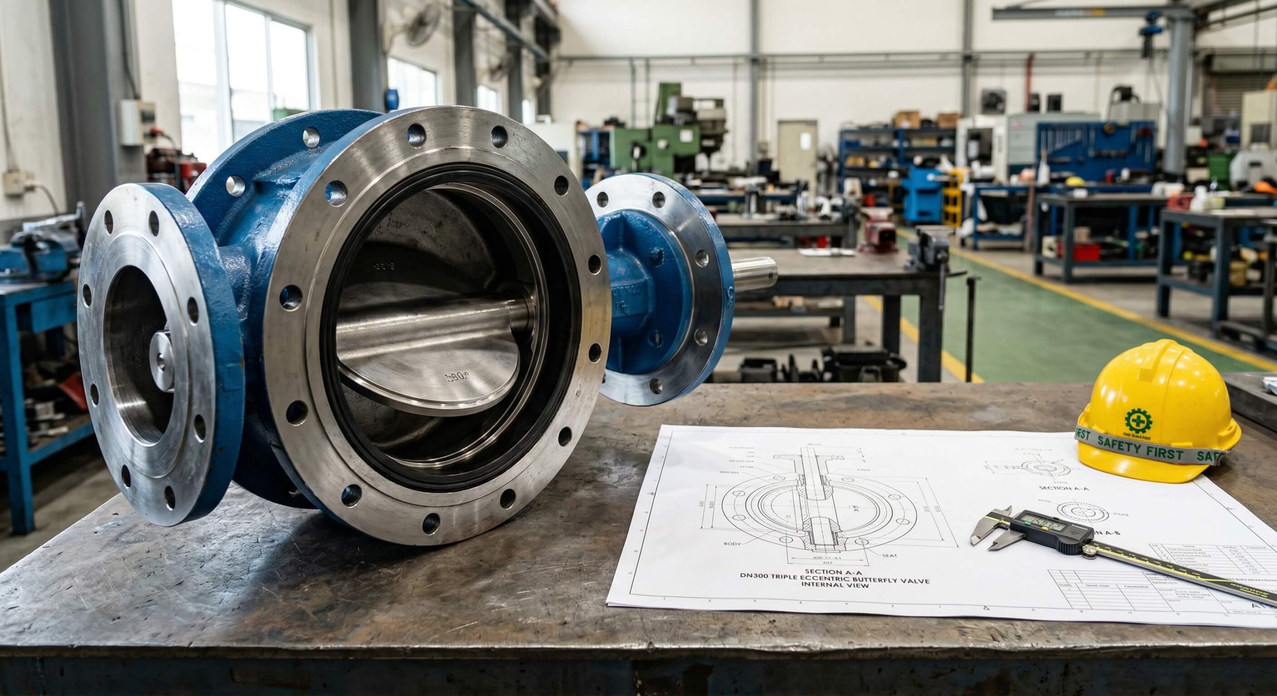
A diagram of butterfly valve illustrates the four primary components: the body, the disc, the stem, and the seat. These parts work in unison to provide a compact and lightweight solution for regulating flow in large-diameter pipes.
Primary Components and Construction
The valve body houses the disc, which is the closing element that rotates to block or allow flow. The stem transmits the necessary torque from the actuator to the disc for precise movement.
- Body: Provides the structural pressure boundary.
- Disc: The primary flow control element.
- Stem: The shaft connecting the actuator and disc.
- Seat: The interior lining that provides the seal.
Here is the kicker: without a high-quality seat, even the most durable disc will fail to prevent bypass.
Comparison with Ball Valves
While both are quarter-turn, butterfly valves are significantly more space-efficient than traditional ball valves. They provide a lower weight profile, which reduces the need for heavy piping supports in large installations.
- Weight: Significantly lower in butterfly designs.
- Cost: More economical for pipe sizes over 6 inches.
- Maintenance: Generally easier to replace seals in situ.
But there is more:
| Component | Standard Material | Key Industrial Function |
|---|---|---|
| Disc | Stainless Steel | Corrosion Resistance |
| Stem | 416 Stainless Steel | High Strength Support |
| Seat | EPDM / PTFE | Resilient Sealing |
This table highlights how material selection directly influences the valve’s ability to handle specific industrial media and stresses.
Key Takeaway: Understanding the relationship between the disc and seat is vital for ensuring long-term, leak-free operation in your facility.
How does a diagram of butterfly valve explain function?
A diagram of butterfly valve demonstrates that the valve functions by rotating a disc 90 degrees to fully open or close the flow path. This quick-acting mechanism makes it ideal for applications requiring rapid isolation or throttling.
The Quarter-Turn Mechanism
When you turn the handle or actuator, the stem rotates the disc from a position parallel to the flow to a position perpendicular to it. This 0 to 90-degree motion allows for gradual flow modulation depending on the angle of the disc.
- 0 Degrees: Fully closed position.
- 45 Degrees: Throttling or flow regulation.
- 90 Degrees: Fully open position.
Why does this matter? Because the speed of operation reduces water hammer risks compared to multi-turn valves.
Preventing Flow Reversal
In many systems, butterfly valves are paired with check valves to ensure that fluid does not flow backward when the pump stops. This combination protects the butterfly valve disc from reverse-pressure damage.
- Swing Check: Prevents backflow in horizontal lines.
- Dual Plate: Offers low pressure drop.
- Spring Loaded: Ensures fast closure in vertical lines.
Here is the kicker:
| Operational Feature | Typical Performance | Benefit to User |
|---|---|---|
| Operating Speed | < 1 second (actuated) | Rapid system shutdown |
| Flow Pattern | Symmetric | Predictable throttling |
| Sealing Type | Bi-directional | Versatile installation |
The data shows that the butterfly valve’s speed and flow symmetry make it a top choice for automated safety systems.
Key Takeaway: Mastering the quarter-turn logic allows you to optimize flow regulation and prevent sudden system surges.
Why use a wafer style diagram of butterfly valve?
A wafer style diagram of butterfly valve shows a design meant to be clamped between two pipe flanges using long bolts. This design is primarily used to maintain a seal against bi-directional pressure differentials and to prevent backflow in systems.
Features of Wafer Butterfly Valves
Wafer valves are the most economical option because they use less material and have a narrower profile. They are designed to fit snugly between flanges, making them incredibly easy to install in tight spaces.
- Body Profile: Extremely thin and lightweight.
- Bolting: Uses through-bolts that span both flanges.
- Cost: Lowest initial investment for large pipelines.
But that is only half the story:
Advantages of Lug Body Designs
Unlike wafer types, lug valves have threaded inserts (lugs) that allow them to be bolted directly to each flange. This allows you to disconnect one side of the piping without disturbing the other side, which is known as dead-end service.
- Threads: Built-in threaded holes for bolts.
- Safety: Superior for downstream maintenance.
- Stability: Better for high-vibration environments.
Why does this matter?
| Body Type | Installation Type | Best Use Case |
|---|---|---|
| Wafer | Sandwich (Clamped) | Budget-sensitive general flow |
| Lug | Threaded (Bolted) | Dead-end service & maintenance |
This comparison clarifies which body style provides the necessary safety margins for your specific maintenance protocols.
Key Takeaway: Selecting the wafer type saves on initial costs, while the lugged design provides essential safety for downstream maintenance.
When to select a flanged diagram of butterfly valve?
A diagram of butterfly valve with flanged ends depicts a heavy-duty body designed for the largest pipe diameters and high-pressure water treatment systems. These valves feature integrated flanges that match the piping standard for a robust, bolted connection.
Benefits of Flanged Ends
Flanged butterfly valves are the standard for massive infrastructure projects, such as municipal water lines. They provide the structural integrity required to handle the weight and pressure of large-scale fluid transport.
- Standards: Compliant with DIN, EN, and API.
- Sealing: Heavy-duty gaskets ensure zero leakage.
- Size: Available up to DN3000 for massive flow.
But there is more:
High-Pressure Tolerance
Because the flanges are part of the valve body, the assembly is much more stable under high flow rates. This stability prevents the valve from shifting or vibrating, which could lead to seal failure over time.
- Stability: Resists axial piping loads.
- Durability: Longer service life in heavy industry.
- Access: Easier to inspect the seal during shutdowns.
Here is the kicker:
| Standard | Pressure Rating | Common Size Range |
|---|---|---|
| DIN / EN | PN10 – PN40 | DN50 – DN3000 |
| ASME / API | Class 150 – 300 | 2″ – 120″ |
Choosing the correct flange standard ensures that your valve integrates perfectly with existing global piping infrastructure.
Key Takeaway: Flanged designs are the superior choice for high-flow, large-diameter systems where structural stability is the primary concern.
What is shown by a diagram of butterfly valve offset?
A diagram of butterfly valve offset illustrates the physical displacement of the stem relative to the centerline of the disc and seat. This design variation is the primary factor determining the valve’s pressure capability and sealing performance.
Concentric Design Limits
In a concentric or “zero-offset” design, the stem passes through the center of the disc and the center of the pipe. While cost-effective, the disc is in constant contact with the seat, which can cause premature wear in high-cycle applications.
- Seat: Usually resilient (EPDM or NBR).
- Pressure: Limited to lower pressure ranges.
- Friction: High friction during the entire rotation.
It sounds simple, right?
Double Offset Benefits
The double offset design moves the stem away from the disc’s centerline and to one side of the valve body. This creates a cam action that lifts the disc off the seat quickly, significantly reducing friction and extending the life of the seal.
- Mechanism: Cam-like movement reduces wear.
- Sealing: Often uses high-performance PTFE seats.
- Application: Ideal for chemical and steam lines.
But that is only the beginning:
| Offset Type | Seat Material | Max Temperature |
|---|---|---|
| Zero Offset | Resilient (Rubber) | Up to 120°C |
| Double Offset | PTFE / High Perf | Up to 200°C |
Using this data allows you to match the offset geometry to your system’s temperature and cycling frequency.
Key Takeaway: Transitioning from concentric to double offset designs can drastically reduce your maintenance intervals in high-cycle systems.
Why is triple offset in a diagram of butterfly valve vital?
A diagram of butterfly valve featuring triple offset technology shows a complex geometry where the sealing cone is tilted. This design allows for a metal-to-metal, bubble-tight seal that can withstand extreme temperatures and pressures.
Geometry of Zero Leakage
The “third offset” is the inclined axis of the seat’s cone shape, which eliminates all rubbing between the disc and the seat. This means the valve only contacts the seat at the final point of closure, preventing the seal from wearing out.
- Contact: Only occurs at the moment of shutoff.
- Seat: Metal-to-metal for fire-safe performance.
- Torque: Lower torque requirements for automation.
Why does this matter?
Alternatives Like Gate Valves
Triple offset valves (TOVs) are increasingly replacing gate valves in critical processes. They offer a much lighter weight and a smaller footprint while providing the same “bubble-tight” shutoff capability.
- Space: Takes up 70% less room than gate valves.
- Weight: Up to 60% lighter for easier installation.
- Control: Offers better throttling than a gate valve.
Here is the kicker:
| Feature | Triple Offset Valve | Gate Valve |
|---|---|---|
| Sealing | Bubble-Tight | Metal-to-Metal |
| Weight | Low | Very High |
| Operation | 90° Turn | Multi-Turn |
The table proves that TOVs provide a more modern, efficient solution for high-performance industrial isolation.
Key Takeaway: Triple offset valves are the industry standard for extreme environments where zero-leakage and fire-safety are non-negotiable.
Which materials suit a diagram of butterfly valve build?
A diagram of butterfly valve helps identify which materials are used for the body, disc, and seat to resist corrosion and erosion. Choosing the wrong material can lead to rapid valve degradation and hazardous leaks in your facility.
Body and Disc Metal Options
Ductile iron is the standard for water applications, while stainless steel is preferred for corrosive chemicals. Carbon steel remains the go-to choice for high-temperature steam and oil-and-gas midstream operations.
- Ductile Iron: Best for municipal and HVAC.
- Stainless Steel: Superior for acids and food grade.
- Carbon Steel: High strength for steam and oil.
You might be wondering:
Resilient vs Metal Sealing
Resilient seats like EPDM provide excellent sealing for water, but they cannot handle abrasive or high-heat media. Metal seats, often reinforced with Stellite, are required for handling slurries or high-pressure steam.
- EPDM/NBR: Ideal for general water service.
- PTFE: Excellent for aggressive chemicals.
- Metal Seat: Necessary for 200°C+ applications.
But there is more:
| Media Type | Recommended Disc | Recommended Seat |
|---|---|---|
| Potable Water | Ductile Iron (Nylon Coated) | EPDM (WRAS) |
| Abrasive Slurry | Stainless Steel 316 | Reinforced Metal |
| Corrosive Acid | SS316 / Hastelloy | PTFE / PFA |
This guide ensures your material choices align with the chemical and physical demands of your process media.
Key Takeaway: Material compatibility is the foundation of valve longevity; always match your disc and seat to the specific chemical properties of your fluid.
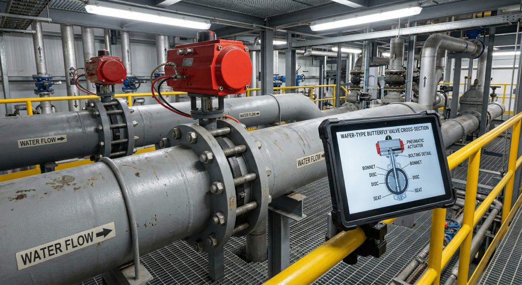
How to automate a diagram of butterfly valve properly?
A diagram of butterfly valve with an actuator shows how mechanical, pneumatic, or electric energy is converted into the torque needed to rotate the disc. Automation is essential for modern plants that require remote monitoring and precise process control.
Manual Handles and Gear Boxes
For smaller valves or systems that don’t change often, a manual lever-lock handle is sufficient. Larger valves require a worm-gear operator to provide the mechanical advantage needed to overcome high fluid pressure.
- Lever Handle: Quick operation for small bores.
- Worm Gear: High torque for large diameters.
- Locking: Prevents accidental valve movement.
Let’s look closer:
Pneumatic and Electric Automation
Pneumatic actuators are the fastest and most cost-effective for plants with existing compressed air. Electric actuators are preferred for remote locations where air lines are unavailable and offer the best integration with PLC systems.
- Pneumatic: Fast, reliable, and explosion-proof.
- Electric: Precise positioning and easy wiring.
- Feedback: Provides real-time status to your control room.
But that is only half the story:
| Actuator Type | Operating Speed | Best Environment |
|---|---|---|
| Manual Lever | Instant | Low-frequency service |
| Pneumatic | < 2 Seconds | High-cycle manufacturing |
| Electric | 10-30 Seconds | Remote / Precision control |
The data indicates that pneumatic systems are best for rapid safety shutoffs, while electric models excel in precision throttling.
Key Takeaway: Selecting the right actuation method ensures your system remains responsive and can be safely managed from a distance.
How to check a diagram of butterfly valve for wear?
A diagram of butterfly valve provides a checklist for maintenance technicians to identify critical wear points before they lead to failure. Regular inspection is the only way to avoid the high costs of unplanned emergency shutdowns.
Routine Inspection Checklists
You should perform a visual inspection of the stem packing and seat every six months. Cycling the valve regularly prevents the disc from seizing and allows you to verify that the actuator is providing enough torque.
- Seals: Check for cracks or hardening.
- Stem: Look for signs of leakage or corrosion.
- Bolts: Ensure all flange bolts are torqued.
- Cycles: Perform “exercise” rotations to prevent sticking.
Why does this matter?
Troubleshooting Common Issues
If you notice a leak through the valve when it is closed, the seat is likely worn or the disc is misaligned. Stem leaks are usually solved by tightening the packing gland or replacing the O-rings.
- Internal Leak: Seat damage or disc debris.
- External Leak: Stem packing failure.
- High Torque: Stem corrosion or seat swelling.
The bottom line?
| Maintenance Task | Frequency | Estimated Time |
|---|---|---|
| Visual Leak Check | Monthly | 5 Minutes |
| Operational Test | Quarterly | 10 Minutes |
| Seal Replacement | 3-5 Years | 2 Hours |
This schedule shows that minimal preventive effort can significantly extend the operational life of your assets.
Key Takeaway: Preventive maintenance reduces the total cost of ownership by up to 30% by catching small seal issues before they become catastrophic failures.
Where to buy an industrial diagram of butterfly valve?
A diagram of butterfly valve from a reputable manufacturer ensures that every component meets international safety and quality standards. Finding a partner who provides technical documentation and traceable test reports is critical for EPC and OEM projects.
Evaluating Global Manufacturers
You must look for suppliers who hold ISO 9001, CE, and DNV certifications to ensure product reliability. A quality manufacturer will provide detailed about pages that highlight their testing facilities and material sourcing.
- Testing: 100% hydro-testing at 1.5x pressure.
- Traceability: Batch-level material certificates.
- Support: 24-hour technical response window.
But there is more:
Why Ruitoflow is the Standard
Ruitoflow delivers precision-engineered solutions that are trusted by industry leaders across Europe, Asia, and North America. Our valves are designed for durability, featuring 99.5% quality reliability and a 12-month comprehensive warranty.
- Lead Time: 5-25 days for most orders.
- Customization: Engineered-to-spec for complex needs.
- Compliance: Standards including DIN, EN, and API.
Why does this matter?
| Manufacturer Metric | Ruitoflow Standard | Industry Average |
|---|---|---|
| Defect Rate | < 0.5% | 2.0% – 3.0% |
| Quote Response | < 24 Hours | 3 – 5 Days |
| Test Coverage | 100% | 85% – 90% |
This performance data demonstrates why choosing a specialized manufacturer is the safest route for your procurement team.
Key Takeaway: Partnering with a certified manufacturer like Ruitoflow provides the technical documentation and product reliability required for modern industrial compliance.
Frequently Asked Questions
Can I use a butterfly valve for high-pressure steam applications?
Yes, but you must select a triple offset valve with metal seating. Standard resilient-seated valves will melt under steam temperatures, whereas triple offset designs provide the necessary heat resistance and zero-leakage performance.
What’s the best material for a valve seat in corrosive chemical lines?
PTFE (Teflon) is generally the best choice for aggressive chemicals. It offers nearly universal chemical resistance and can handle temperatures up to 200°C, making it superior to standard rubbers like EPDM.
Can I install a butterfly valve in any orientation?
Yes, butterfly valves can be installed horizontally or vertically. However, for fluids with suspended solids, it is recommended to install the stem horizontally to prevent sediment from building up in the bottom bearing.
What’s the best way to automate a flanged valve for remote operation?
A pneumatic actuator with a positioner is the most efficient choice for most plants. Pneumatic systems offer the fastest response times and are inherently safer in environments with flammable gases compared to basic electric motors.
How do I know if I need a double or triple offset valve?
You need at least a double offset valve if your system operates above 120°C or involves frequent cycling. If you require bubble-tight shutoff in high-pressure or high-temperature steam, the triple offset design is the only reliable option.
Conclusion
Selecting the right industrial butterfly valve is a critical decision that directly impacts the safety and productivity of your facility. By understanding the nuances between body types, offset geometries, and material compositions, you can eliminate costly leaks and extend your equipment’s service life. Ruitoflow is dedicated to engineering high-precision valves that meet global standards for durability and performance. Whether you need custom materials or rapid replacements for a municipal project, our team is ready to deliver.
Contact us today to receive a technical consultation and quote for your next fluid control project.