To bypass errors for lugged butterfly valves requires correct bolt torque alongside clean flanges and aligned pipes. Many technicians face leaky pipes or damaged seats after setting up their systems. A failed seal wastes time. Money slips away fast. Here stands a better way: following a proper lug butterfly valve installation method stops leaks instantly. We provide proven techniques designed for lasting success.
Stop bolt stress in lug butterfly valve installation?
Stopping bolt stress requires tightening hardware evenly following manufacturer limits. Excessive force warps a rubber seat during lug butterfly valve installation causing instant leakage. Overtightening damages a core seal permanently. Hardware failure happens fast.
What happens when bolts clamp down poorly?
Applying too much torque crushes that elastomer seat right away. A distorted sealing surface creates gaps against your metal disc. Pressure drops occur immediately across any system. Your maintenance team spends hours troubleshooting unexpected drips.
Strategies for applying balanced mechanical force
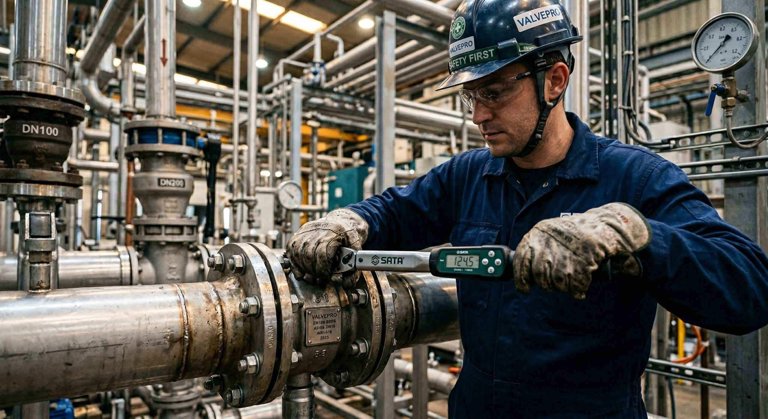
You might be wondering: how much torque ruins parts? Mechanics often rely on muscle memory rather than calibrated wrenches. This habit destroys resilient seats. Working in a star pattern keeps flange pressure balanced perfectly. Technicians must tighten nuts gradually rather than locking one side down completely. A torque wrench acts as your best defense against deformed components.
- Apply light tension uniformly across all points.
- Follow a diagonal cross sequence repeatedly.
- Never exceed a recommended ft-lbs rating.
Key Takeaway: Symmetrical tightening protects that seat profile while extending hardware lifespan.
| Parameter | Improper Tightening | Correct Star Pattern |
|---|---|---|
| Seat Compression | Uneven crushing | Uniform sealing force |
| Leakage Risk | Very high | Nearly zero |
| Flange Stress | Focused on one side | Distributed evenly |
| Torque Method | Single pass tightening | Gradual multi-step |
Using a balanced approach prevents uneven seat wear while extending system longevity.
Why clean flanges in lug butterfly valve installation?
Cleaning flanges prevents foreign debris from ruining your seal integrity immediately. Leftover weld slag scratches components during lug butterfly valve installation creating permanent leak paths. Rust acts like sandpaper against soft elastomer materials. Dirt trapped between mating surfaces guarantees poor performance.
What debris causes most damage?
Metal shavings from nearby welding jobs pose severe threats instantly. Old sealant fragments harden into sharp edges inside pipes. Any stray oil degrades rubber seats fast. Unseen grime compromises performance before operations even start.
Best practices for flange preparation
What’s the real story? Skipping surface preparation dooms your project from day one. Wiping down metal faces takes five minutes but saves thousands. Workers must scrub all mating surfaces using appropriate wire brushes carefully. Removing grease requires industrial solvents matched appropriately for specific pipe materials.
- Sweep away loose dirt before mounting anything.
- Scrape off old gasket residues completely.
- Wipe everything dry with clean rags.
Key Takeaway: Immaculate pipe faces protect delicate resilient materials from immediate destruction.
| Debris Type | Direct Consequence | Prevention Method |
|---|---|---|
| Weld Slag | Scratches metal plate | Heavy wire brushing |
| Old Sealant | Creates uneven gaps | Thorough scraping |
| Oil/Grease | Degrades rubber seat | Solvent wiping |
| Rust Flakes | Acts as abrasive | Grinding or sanding |
Clean mating surfaces guarantee proper sealing alignment while eliminating friction points.
How does piping align in lug butterfly valve installation?
Piping aligns correctly when free-threading bolts pass through holes without resistance. Forcing misaligned pipes during lug butterfly valve installation strains body castings severely. Heavy mechanical stress distorts internal dimensions fast. A skewed setup prevents discs from closing completely.
Recognizing severe misalignment issues
Pipes offset by a fraction of an inch create massive headaches. Workers struggling with hammer blows indicate terrible structural positioning. Visible gaps on one flange side mean trouble. Any angled approach puts lateral force directly onto your equipment.
Steps for achieving perfect geometric alignment
Think about this: heavy machinery cannot fix bad pipe geometry. You risk cracking cast iron components when forcing things. Installers must square both pipe ends before lifting heavy sections. Using hydraulic alignment tools gently brings stubborn sections into place.
- Check gap distances across four quadrants.
- Support heavy pipe runs using adjustable hangers.
- Slide bolts through holes manually.
Key Takeaway: Perfect geometric alignment eliminates undue mechanical stress keeping castings intact.
| Alignment Issue | Immediate Effect | Long-term Risk |
|---|---|---|
| Angular offset | Pinched rubber seat | Permanent deformation |
| Lateral shift | Difficult bolt insertion | Cracked flange casting |
| Excessive gap | Stretching pipe ends | Weld joint failure |
| Torsional twist | Bind during operation | Broken actuator stem |
Addressing structural geometry prior to tightening prevents catastrophic body fractures down the road.
Why check flow for your lug butterfly valve installation?
Checking flow direction prevents inverted mounting which causes severe hydrodynamic instability. Ignoring arrows during lug butterfly valve installation creates unexpected turbulence inside lines. Some specialized designs feature offset shafts requiring specific orientations. Reverse flow slams discs against their sealing limits unnaturally.
The dangers of reverse fluid movement
Certain high-performance models seal tightly against one specific pressure direction only. Installing them backward reduces their maximum pressure rating significantly. Fluid hammering occurs when liquid strikes unsupported disc faces. System vibration increases dramatically under these harsh conditions.
Finding and following directional arrows
Think about it: backwards placement turns an engineered flow control device into a restriction plate. Your pumps work harder overcoming artificial resistance. Manufacturers stamp large indicator marks directly onto cast metal bodies clearly. You must match these markings with system fluid movement precisely.
- Locate cast arrows on body sides.
- Verify expected fluid paths beforehand.
- Double-check actuator mounting positions.
Key Takeaway: Respecting engineered flow paths improves efficiency while preventing premature component degradation.
| Flow Condition | Proper Orientation | Reversed Orientation |
|---|---|---|
| Sealing capability | Maximum rated pressure | Severely reduced pressure |
| Flow resistance | Minimal turbulence | High friction loss |
| Component stress | Supported by shaft | Forced against seat |
| Operational noise | Quiet running | High vibration |
Orienting equipment correctly aligns internal geometries with fluid dynamics perfectly.
Do system stresses ruin lug butterfly valve installation?
Unmanaged system stresses crack valve bodies through extreme thermal or mechanical forces. Rigid pipework during lug butterfly valve installation concentrates expansion forces directly into cast metal. Temperature fluctuations make steel pipes grow linearly. That sudden movement transfers massive strain onto anchored points.
Understanding thermal expansion risks
Hot fluids pumping through cold lines cause rapid dimensional changes instantly. Without flexible joints, expanding pipes push forcefully against solid barriers. Cast iron components lack elasticity compared with carbon steel pipes. Those localized pressures fracture brittle castings effortlessly.
Integrating proper expansion joints
Get this: rigid networks destroy equipment faster than regular wear and tear. You need buffer zones. Placing rubber compensators near working units absorbs linear pipe growth effectively. Installers utilize sliding supports allowing natural movement along structural axes.
- Install rubber bellows nearby.
- Use sliding anchor points.
- Calculate expected thermal growth beforehand.
Key Takeaway: Incorporating flexible elements isolates delicate equipment from destructive environmental forces.
| Stress Source | Impact on Equipment | Recommended Solution |
|---|---|---|
| Thermal expansion | Cracks cast iron bodies | Install rubber compensators |
| Vibration | Loosens flange bolts | Add dampening supports |
| Water hammer | Shatters internal discs | Use slow-closing actuators |
| Misaligned weight | Bends operating stems | Provide independent hangers |
Managing kinetic energy within pipe networks preserves physical integrity across operating cycles.
What risks hurt seats in lug butterfly valve installation?
Pinching resilient materials between sharp metal flanges slices through rubber quickly. Failing to open a disc slightly during lug butterfly valve installation tears elastomer surfaces. Fully closed discs press outward against lining walls heavily. Tightening bolts while fully shut locks deformed rubber permanently.
How improper disc positioning destroys seals
Leaving discs one hundred percent closed during mounting creates friction traps. Flange compression forces bulge internal rubber linings toward center spaces. Moving that disc later shreds newly formed rubber lips instantly. Workers hear a distinct tearing sound when forcing handles.
Safe handling procedures for elastomers
Ready for a secret? Cracking your handle open ten degrees saves that entire seal. This tiny gap allows rubber compression without binding. Technicians should lubricate mating surfaces using approved silicone compounds sparingly. Keeping protective covers intact until final placement blocks stray debris.
- Open discs slightly prior to bolting.
- Avoid petroleum lubricants on EPDM.
- Check inner diameters for clearance.
Key takeaway: Managing physical clearance protects soft compounds from mechanical shearing forces.
| Handling Error | Damage Mechanism | Resulting Failure |
|---|---|---|
| Fully closed install | Pinches disc against rubber | Tears upon first opening |
| Petroleum grease | Chemically attacks EPDM | Swelling and degradation |
| Sharp pipe edges | Slices resilient facing | Permanent surface scoring |
| Dropping equipment | Deforms internal lining | Loss of bubble-tight seal |
Leaving slight operating gaps allows elastomers room for natural displacement under pressure.
How do gaskets fit into lug butterfly valve installation?
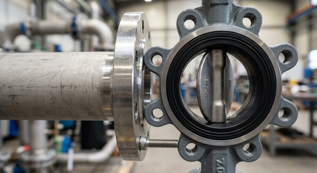
Standard molded seats act as their own gaskets rendering additional seals unnecessary. Adding extra flat rings during lug butterfly valve installation causes dangerous over-compression. Too much material sandwiched between flanges pushes rubber inwards. That inward bulge blocks normal disc rotation completely.
Why double gasketing fails terribly
Maintenance crews sometimes stack extra seals hoping for better leak prevention. This misguided strategy multiplies failure points across mating surfaces. Thickened joints require extreme bolt lengths causing uneven tension distribution. Extra rubber squeezes into flow paths creating flow restrictions.
Recognizing when external seals apply
Truth be told… extra parts often ruin perfectly engineered designs. Your built-in resilient lining handles everything alone. Certain high-performance metal-seated models do require separate graphite rings. Installers must read specification sheets confirming exact sealing requirements thoroughly.
- Check if seats extend past body faces.
- Never use flat gaskets with molded liners.
- Match flange faces properly.
Key Takeaway: Trusting integrated seat designs prevents dimensional stacking issues while guaranteeing smooth operation.
| Valve Type | Integrated Seal | External Gasket Required |
|---|---|---|
| Resilient Seated | Yes (molded face) | No |
| High-Performance | Varies by design | Yes (usually spiral wound) |
| Triple Offset | Metal-to-metal | Yes (graphite or metal) |
| AWWA Standard | Usually molded | No |
Following factory sealing guidelines prevents disastrous over-packing within bolted joints.
Why position actuators in lug butterfly valve installation?
Positioning actuators vertically prevents heavy motors from applying side loads onto stems. Horizontal mounting during lug butterfly valve installation stresses packing glands unnecessarily. Gravity pulls massive pneumatic cylinders downward bending internal shafts. A bent stem destroys upper seals causing rapid environmental leaks.
The mechanics of side loading
Heavy electrical gear hanging sideways creates massive leverage against bronze bushings. Continuous operation under these conditions wears out internal bearings rapidly. Friction increases dramatically requiring more torque for simple rotations. Motors burn out trying to overcome this artificial mechanical drag.
Securing heavy control mechanisms
Watch out for this: an unbalanced setup voids factory warranties immediately. You must support heavy attachments independently. Engineers design sturdy bracket systems supporting overhanging weight safely. Installing vertical configurations keeps forces perfectly aligned with gravitational pulls.
- Mount stems pointing straight up whenever possible.
- Support large cylinders using dedicated racks.
- Inspect connecting brackets regularly.
Key Takeaway: Balancing equipment weight along central axes preserves shaft straightness while protecting delicate packings.
| Actuator Position | Shaft Stress Level | Bearing Wear Rate |
|---|---|---|
| Vertical (Upright) | Minimal | Very low |
| Horizontal (Unsupported) | Extreme side load | Accelerated |
| Horizontal (Supported) | Moderate | Normal |
| Upside Down | Fluid drains into gear | High risk |
Keeping heavy control tops balanced properly maintains long-lasting mechanical functionality.
How to pressure test a lug butterfly valve installation?
Testing pipelines gradually reveals hidden weaknesses without shattering brittle system components. Slamming lines with maximum force during lug butterfly valve installation creates dangerous water hammers. Sudden pressure spikes blow out newly compressed seals instantly. Controlled hydrostatic testing verifies joint integrity safely.
Avoiding shock waves during tests
Opening pumps rapidly sends destructive shock waves traveling down pipe runs. These invisible forces slam into closed discs bending heavy metal plates. Surging liquids displace resilient seats pushing them completely out of alignment. Equipment fractures under unmanaged dynamic fluid strikes.
Executing a safe hydrostatic check
This changes everything: slow pressurization allows trapped air pockets enough time for safe escape. You maintain total control over kinetic forces. Operators must bleed off atmospheric air through highest elevation vents entirely. Ramping up water pressure incrementally identifies minor weeps before major blowouts happen.
- Open bypass lines filling systems slowly.
- Monitor gauges for unexpected pressure drops.
- Keep personnel away from pressurized flanges.
Key Takeaway: Gradual fluid introduction protects mechanical assemblies from catastrophic dynamic overloading.
| Testing Method | Pressure Application | Risk of Component Damage |
|---|---|---|
| Shock Pressurization | Instant max pressure | Extremely high |
| Incremental Stepping | 25% jumps | Low |
| Slow Ramp | Continuous gradual rise | Minimal |
| Gas Testing | Highly compressible | High danger if ruptured |
Ramping up internal loads methodically verifies structural soundness safely.
What upkeep follows a lug butterfly valve installation?
Routine maintenance keeps moving parts functional years after initial setup. Neglecting visual inspections following lug butterfly valve installation allows minor leaks to worsen. Rust forms on exposed threads locking nuts tightly against flanges. Packing glands dry out losing their elasticity.
Implementing a preventive care schedule
Technicians walking factory floors catch dripping fluids before disasters strike. Applying light oil onto exposed stem areas prevents aggressive atmospheric corrosion. Exercising infrequently used equipment breaks calcium deposits loose safely. Stagnant systems suffer from internal scale buildup rapidly.
Mandatory monthly checklist items
Consider this fact: preventative action costs pennies compared with emergency shutdowns. You protect massive capital investments through simple awareness. Crews should check fastener tightness using calibrated tools periodically. Listening for unusual scraping sounds during operation indicates internal wear early.
- Verify actuator travel limits remain accurate.
- Clean external debris off moving parts.
- Check pneumatic air line connections.
Key Takeaway: Consistent monitoring spots developing faults well before causing complete operational failure.
| Maintenance Task | Frequency | Purpose |
|---|---|---|
| Visual Leak Check | Weekly | Spot external fluid escape |
| Valve Exercising | Monthly | Prevent scale lockup |
| Fastener Torque | Annually | Compensate for vibration |
| Actuator Calibration | Bi-annually | Ensure accurate positioning |
Following strict preventative schedules maximizes return on investment indefinitely.
Securing Your System Permanently
Ending your alignment struggles stops costly plant shutdowns permanently. We provide rugged flow control devices built for enduring intense industrial conditions seamlessly. Reaching out for professional guidance helps operators select perfect materials matched for specific chemical environments. A dedicated team answers technical questions fast. Quality engineering builds safer working spaces everywhere. Feel free to contact us today for personalized sizing recommendations.
FAQ
Q1: Can I use standard flat gaskets with my molded seat?
No, you cannot. Standard resilient liners act as built-in seals. Adding extra rubber causes dangerous over-compression inside flanges.
Q2: What’s the best way to tighten mounting hardware?
The best way relies on a star pattern sequence. Crossing back and forth distributes mechanical force evenly across delicate components.
Q3: How do I know if my alignment is bad?
You know bad alignment exists when bolts refuse easy manual insertion. Forcing pipes together with machinery indicates severe structural problems.
Q4: Can I install my equipment backward?
No, backwards mounting reduces maximum pressure ratings significantly. Fluid dynamics behave differently depending on engineered internal geometry paths.
Q5: What’s the best position for heavy actuators?
A vertical upright position provides maximum stability. Hanging heavy motors horizontally bends stems while wearing out bronze bearings rapidly.