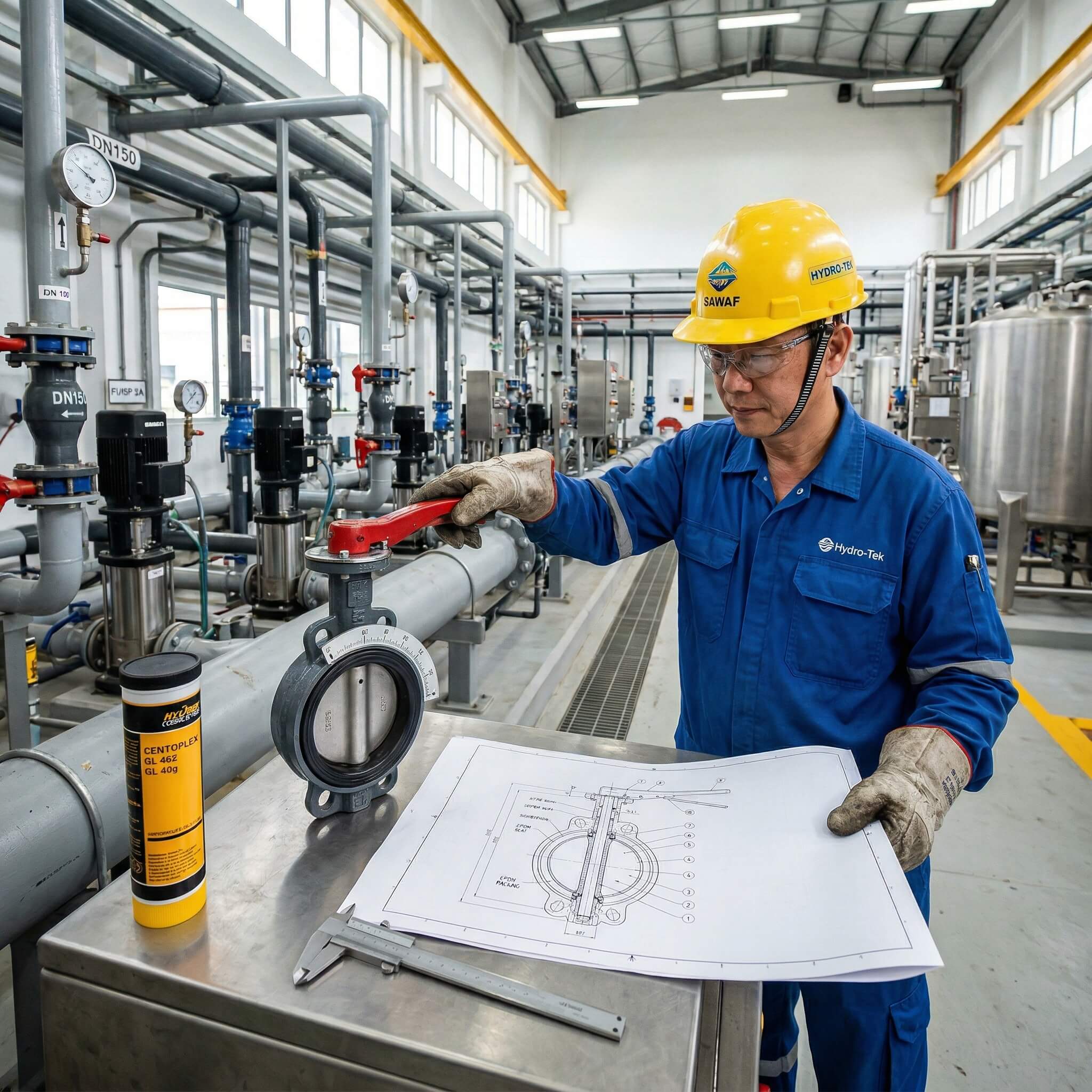
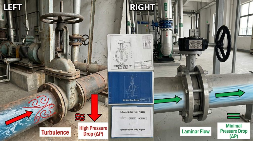
An industrial butterfly valve is a quarter-turn rotary motion valve used for stopping, regulating, and starting fluid flow in a piping system. You likely face the constant struggle of managing bulky isolation equipment that creates significant pressure drops and drives up maintenance costs. This inefficiency agitates your bottom line and risks system downtime during critical production cycles. By reviewing a professional butterfly valve schematic, you can implement a compact, high-efficiency solution that optimizes flow control without the heavy footprint of traditional gate valves.
What is a butterfly valve schematic and its design?
A butterfly valve schematic illustrates a design where a circular disc rotates around a central shaft to modulate or block the passage of media. You will notice that the core architecture is remarkably thin, allowing for a lightweight profile that reduces structural stress on your pipes. This design focuses on a 90-degree rotation, transforming the valve from a fully closed state to a fully open one with minimal effort.
What are the main components of the design?
The primary components typically include the valve body, a rotating disc, a stem, and a resilient seat. These parts work in unison to provide a tight seal when the disc is turned perpendicular to the flow direction.
Check this out:
- Valve Body: The outer shell that connects to the piping system.
- Disc: The circular plate that acts as the flow control element.
- Stem: The rod connecting the actuator to the disc.
- Seat: The internal lining that prevents leakage when closed.
Key Takeaway: Understanding the basic components in a butterfly valve schematic allows you to identify potential wear points early, ensuring your isolation systems remain reliable under pressure.
| Component | Function | Material Example |
|---|---|---|
| Body | Housing and Structural Support | Ductile Iron (GGG40/50) |
| Disc | Flow Regulation/Blocking | Stainless Steel (CF8M) |
| Seat | Sealing Interface | EPDM or PTFE |
Use this table to quickly identify the role of each primary part within your specific valve assembly.
How does a butterfly valve schematic show operation?
The operation shown in a butterfly valve schematic relies on a quarter-turn mechanism where the disc moves 90 degrees to facilitate or stop flow. You simply apply torque to the stem, which rotates the disc away from the seat to open the passage. This rapid action makes it one of the most efficient choices for systems requiring quick shut-off capabilities.
How does the quarter-turn mechanism function?
The movement begins when you turn the actuator, causing the stem to spin the disc. In the open position, the disc remains in the flow stream but offers very low resistance compared to other valve types.
Here is the deal:
- 0 Degrees: The valve is fully closed and the disc is perpendicular to flow.
- 45 Degrees: The valve is partially open, often used for throttling.
- 90 Degrees: The valve is fully open and the disc is parallel to flow.
Key Takeaway: The quarter-turn operation is the most efficient way to manage large volumes of fluid with minimal mechanical movement.
| Operating Angle | Flow Status | Pressure Drop |
|---|---|---|
| 0° | Closed | Maximum |
| 45° | Throttling | Medium |
| 90° | Fully Open | Minimal |
This operational sequence highlights how disc position directly impacts system performance and flow velocity.
Why is the wafer butterfly valve schematic unique?
A wafer butterfly valve schematic describes a specialized body style designed to be sandwiched between two pipe flanges. You will see that this valve does not have its own flange holes; instead, long bolts span the entire width of the valve to clamp it into place. This makes it the most economical and space-saving option for your low-to-medium pressure industrial applications.
What makes the wafer style so compact?
The wafer design eliminates the need for bulky body flanges, which significantly reduces the face-to-face dimension of the equipment. This allows you to install it in tight spaces where traditional flanged valves simply would not fit.
Look:
- Lightweight: Easier to handle during installation and maintenance.
- Low Cost: Uses less material during the casting process.
- Versatile: Compatible with various flange standards like ANSI or DIN.
Key Takeaway: Selecting a wafer design is the best way to reduce both initial capital expenditure and structural weight in standard water or HVAC systems.
| Attribute | Wafer Style | Benefit |
|---|---|---|
| Installation | Between Flanges | Space Saving |
| Maintenance | Requires Pipeline Shutdown | Simple Removal |
| Pressure Limit | Typically PN10/PN16 | Cost-Effective |
Analyze these attributes to determine if the wafer’s compact nature aligns with your system’s pressure requirements.
When do you use a lugged butterfly valve schematic?
A lugged butterfly valve schematic features threaded inserts—known as lugs—on the exterior of the valve body that allow for direct bolting to each flange. You should choose this design when you need the ability to disconnect one side of the piping for maintenance while keeping the other side under pressure. This “dead-end service” capability provides a level of safety and operational flexibility that wafer types cannot match.
Can this handle dead-end service effectively?
The threaded lugs allow the valve to stay securely attached to one flange even if the adjacent pipe is removed. This is critical for systems where you need to perform repairs without draining the entire network.
The bottom line:
- Independent Bolting: Each side can be bolted separately to the pipe flanges.
- Safety: Prevents the valve from falling out when one pipe section is removed.
- Pressure Retention: Maintains a seal even in downstream isolation scenarios.
Key Takeaway: Lugged valves are essential for safety-critical zones where downstream maintenance must occur without fully depressurizing the upstream system.
| Service Type | Recommended Valve | Security Level |
|---|---|---|
| Standard Flow | Wafer | Moderate |
| Dead-End Service | Lugged | High |
| High Vibration | Lugged | High |
Evaluate your maintenance schedule to decide if the added security of a lugged body is worth the marginal price increase.
How does a triple offset butterfly valve schematic work?
A triple offset butterfly valve schematic details a sophisticated geometry where three distinct offsets prevent seat wear and ensure zero-leakage performance. You will observe that the disc moves into the seat like a cone, eliminating friction during the entire stroke until the final point of closure. This makes it the superior choice for your high-temperature and high-pressure steam or chemical lines.
What are the three specific offsets?
The first two offsets refer to the shaft position relative to the centerline, while the third is the conical shape of the sealing surface. This combination allows for a “camming” action that protects the metal seat from abrasion.
Think about it:
- Offset 1: The shaft is located behind the sealing surface.
- Offset 2: The shaft is slightly to one side of the vertical centerline.
- Offset 3: The sealing cone angle is tilted away from the valve axis.
Key Takeaway: Triple offset designs provide the zero-leakage of a globe valve with the compact footprint and cost of a butterfly valve.
| Offset Type | Mechanical Effect | Operational Benefit |
|---|---|---|
| Shaft/Seat | Eccentric Rotation | Reduced Friction |
| Shaft/Center | Camming Action | Better Sealing |
| Conical Seat | Wedging Effect | Zero Leakage |
This geometric complexity is what allows the valve to thrive in the most demanding industrial environments.
What does a concentric butterfly valve schematic indicate?
A concentric butterfly valve schematic represents the standard design where the stem passes through the exact center of the disc and seat. You typically find this in resilient seated valves where a rubber liner provides the sealing force against the disc edge. This is your go-to solution for non-critical fluids like water, air, or mild chemicals at lower pressures.
Why is the concentric design so common?
The simplicity of the concentric layout makes it very easy to manufacture and maintain, keeping costs extremely low. Because the disc is always in contact with the seat, it is highly effective for basic on/off operations.
The bottom line:
- Simplicity: Fewer moving parts and a straightforward flow path.
- Cost: The most budget-friendly industrial valve option available.
- Maintenance: Easy to replace the rubber seat liner in the field.
Key Takeaway: Concentric valves offer the best value for general utility services where absolute zero-leakage at high pressure is not the primary requirement.
| Feature | Concentric Style | Application |
|---|---|---|
| Seat Material | EPDM / NBR | Water Treatment |
| Disc Alignment | Centerline | HVAC Systems |
| Pressure Class | Class 125/150 | Low-Pressure Air |
Review this data to see if a concentric valve meets your utility requirements before investing in more complex eccentric models.
How to read a high performance butterfly valve schematic?
Reading a high performance butterfly valve schematic requires identifying the double eccentric shaft position that characterizes these units. You will see that the shaft is offset from the center of the seat, which allows the disc to “lift” off the seat almost immediately upon opening. This reduces seat wear significantly, making it ideal for high-cycle applications in your processing plant.
What defines high performance in these units?
High performance usually refers to the valve’s ability to handle higher pressures (up to PN40) and temperatures that would destroy a standard concentric valve. They often feature reinforced PTFE seats for better chemical and heat resistance.
Look:
- Double Eccentric: The “double” refers to the two offsets of the stem.
- Reduced Torque: Lower friction means you can use smaller, cheaper actuators.
- Durability: Extends the service life by 50% compared to concentric types.
Key Takeaway: High performance valves bridge the gap between basic utility valves and expensive triple offset units for mid-range industrial needs.
| Parameter | Performance Spec | Advantage |
|---|---|---|
| Max Pressure | PN25 / PN40 | High-System Safety |
| Max Temp | Up to 250°C | Process Flexibility |
| Cycle Life | High-Frequency | Lower Maintenance |
Check these specifications to ensure your valve selection matches the cycling demands of your automated system.
How do materials change a butterfly valve schematic?
The materials listed in a butterfly valve schematic dictate the environment in which the valve can safely operate. You must select the right combination of body, disc, and seat materials to prevent corrosion and premature failure. For instance, a stainless steel disc is necessary for corrosive media, while a ductile iron body provides the strength needed for high-pressure water mains.
Which materials are best for corrosive media?
When dealing with aggressive chemicals, you should look for discs made of CF8M (316 SS) or Hastelloy and seats made of Viton or PTFE. These materials resist chemical attack and prevent the valve from seizing over time.
Check this out:
- Ductile Iron: Best for water and general industrial fluids.
- Stainless Steel: Essential for food, beverage, and chemical lines.
- EPDM: The standard for water, but fails quickly in oil-based systems.
- PTFE: Offers nearly universal chemical resistance and high heat tolerance.
Key Takeaway: Matching material compatibility to your media is the single most important factor in preventing catastrophic valve failure.
| Component | Corrosive Service | General Water Service |
|---|---|---|
| Body | SS316 | Ductile Iron |
| Disc | Duplex Steel | SS304 |
| Seat | PTFE | EPDM |
Use this material comparison to verify that your current valve specs are optimized for the fluids you are transporting.
How to maintain a butterfly valve schematic layout?
A butterfly valve schematic serves as your primary reference guide for routine maintenance and troubleshooting. You should use it to identify the location of O-rings, bushings, and packing glands that may require periodic lubrication or replacement. By following a structured maintenance plan, you can extend the life of your equipment and avoid the high costs of emergency shutdowns.
What are the signs that maintenance is required?
The most common signs include an increase in operating torque, visible external leakage at the stem, or internal “passing” when the valve is supposed to be closed. You should inspect the seat integrity every 200 cycles to ensure the sealing surface remains smooth.
Check this out:
- Torque Check: If the valve becomes hard to turn, the stem or seat is likely fouled.
- Leakage Inspection: Check the packing gland for moisture or drips.
- Cleaning: Remove debris from the disc edge to ensure a tight seal.
- Lubrication: Keep the actuator and stem moving smoothly with industrial-grade grease.
Key Takeaway: Proactive maintenance based on the manufacturer’s schematic can prevent 90% of common valve failures in industrial settings.
| Maintenance Task | Frequency | Objective |
|---|---|---|
| Visual Inspection | Monthly | Identify External Leaks |
| Operation Test | Quarterly | Verify Smooth Torque |
| Seat Replacement | As Needed | Restore Zero-Leakage |
Follow this schedule to maintain peak efficiency and ensure your isolation valves are ready when you need them most.
FAQ: What else should you know about the butterfly valve schematic?
Can I install a butterfly valve in a vertical pipe?
Yes. Butterfly valves can be installed in either horizontal or vertical orientations, but for media with suspended solids, a horizontal stem orientation is often preferred to prevent sediment buildup in the lower bearing.
What’s the best way to prevent seat damage during installation?
Keep the valve partially open. Never install a butterfly valve in the fully closed position, as this can cause the seat to deform or pinch against the pipe flanges during tightening.
How do I know if my valve needs a gearbox?
Generally, for sizes above DN150 (6 inches), a manual gearbox or actuator is recommended. The torque required to overcome pressure and friction at larger sizes makes simple lever operation difficult and potentially unsafe for your staff.
Can I use a butterfly valve for steam?
Only with specific designs. Standard concentric valves with rubber seats will fail instantly; you must use a triple offset valve with a metal seat and high-temperature graphite packing for steam service.
How do I size a butterfly valve for throttling?
Avoid sizing based on pipe diameter. Instead, use the flow coefficient (Cv) to ensure the valve is operating between 20% and 70% open to avoid cavitation and seat erosion during modulation.
Conclusion
Industrial butterfly valves represent the most versatile and cost-effective solution for modern fluid transport challenges. From the space-saving wafer design to the extreme reliability of triple offset units, these valves solve the problem of bulky, high-maintenance equipment while offering precise regulation and robust isolation. At Ruitoflow, we combine 15 years of precision engineering with a 99.5% QC pass rate to deliver valves that thrive in the toughest conditions. If you are ready to optimize your flow control or need custom technical guidance, contact us today to speak with our application engineers. Let Ruitoflow be your partner in building more efficient, zero-leakage systems for the future of your industry.