A pneumatic actuator for butterfly valve represents an automated mechanism utilizing compressed gas for pipeline fluid regulation. You often face unpredictable pressure surges that threaten expensive infrastructure constantly. Sudden liquid hammering ruptures pipe seals instantly, costing thousands through unscheduled plant downtime. Automated air-driven hardware provides reliable, split-second closure, protecting valuable processing lines safely.
What is a pneumatic actuator for butterfly valve?
This mechanism acts as an industrial controller driven by compressed gas. Operators deploy a pneumatic actuator for butterfly valve when automating internal disk rotation across complex piping networks. It replaces manual handwheels with high-speed automated power.
What defines this mechanism?
These units translate gas pressure into mechanical motion efficiently. A design typically incorporates internal pistons moving upon exposure toward pressurized air. Here is the deal, such simple movement controls massive liquid volumes perfectly. You gain precise management over aggressive chemicals without risking human safety.
Where do facilities deploy them?
Engineers install robust units across diverse manufacturing environments everywhere. They thrive during situations requiring rapid response times.
- Chemical processing plants
- Municipal water treatment facilities
- Commercial beverage production
- HVAC cooling infrastructures
Main functional benefits
Air-powered operation offers significant advantages over manual alternatives. A notable benefit involves rapid disk rotation speed. You might be wondering, how safe are they? They excel within explosive environments because electrical sparks remain absent entirely.
Key Takeaway: Adopting air-driven control units drastically improves your facility’s response time alongside operational safety margins.
| Feature | Description | Benefit |
|---|---|---|
| Power Source | Compressed Air | Rapid actuation speed |
| Safety Rating | Intrinsically Safe | Perfect for explosive zones |
| Drive Type | Rack and Pinion | Consistent torque output |
This comparison shows how air-powered systems deliver superior safety metrics against manual options.
How does a pneumatic actuator for butterfly valve work?
This device operates by forcing compressed air against internal mechanical pistons. Fluid control systems rely on reliable gas pressure mechanics daily. A pneumatic actuator for butterfly valve transforms pneumatic energy into quarter-turn rotational force effortlessly. You can regulate flow rates quickly using automated signals.
Initial signal reception
Solenoids dictate exact moments air enters internal chambers. Electric pulses trigger these small directional components instantly. But here’s the kicker, operations happen within fractions of a second. Precision timing prevents liquid hammering during sudden line closures.
Piston movement mechanics
Pressurized gas fills cylinder cavities rapidly. Expanding volume pushes metal racks horizontally across central pinions. Operators monitor these physical transitions via feedback sensors.
- Internal gears interlock tightly
- Seals prevent pressure leaks
- Bearings reduce rotational friction
Reversing disk direction
Spring mechanisms provide opposing force during power losses automatically. Stored mechanical energy pushes components backward when air bleeds away. This is where it gets interesting, fail-safe configurations protect vulnerable pipe sections during total plant blackouts.
Key Takeaway: Understanding internal mechanical sequences helps engineers troubleshoot slow response times effectively.
| Component | Function | Failure Result |
|---|---|---|
| Solenoid | Directs gas flow | Total system unresponsiveness |
| Pinion Gear | Rotates central stem | Disk remains stuck |
| Return Spring | Provides backup force | Fails open or closed |
Analyzing component responsibilities clarifies maintenance priorities regarding automated flow networks.
Why choose a pneumatic actuator for butterfly valve?
Facility managers select these devices because they offer unmatched reliability under harsh conditions. Installing a pneumatic actuator for butterfly valve reduces manual labor requirements across sprawling factory floors. They handle high-cycle operations without suffering premature metal fatigue.
Cost effectiveness benefits
Initial capital investments remain lower than heavy-duty electric motor equivalents. Factories save substantial budget funds when outfitting extensive piping networks. What’s the real story? Simplified internal designs require fewer replacement parts over decades of continuous usage.
Operational speed advantages
Quarter-turn mechanisms require minimal time completing full open-close cycles.
- Emergency shutoffs occur instantly
- Batch processing times decrease
- System bleeding happens rapidly
Environmental durability factors
Aluminum housings resist corrosive atmospheres effectively outdoors. Industrial coatings protect sensitive internal springs against airborne moisture. Think about it, avoiding electrical shorts in wet environments keeps workers safe.
Key Takeaway: Prioritizing air-powered automation delivers excellent return on investment through reduced maintenance overhead.
| Advantage | Metric | Impact |
|---|---|---|
| Speed | < 1 second | Prevents catastrophic overflows |
| Cost | Low initial price | Maximizes facility budgets |
| Lifespan | 1 Million cycles | Lowers replacement frequency |
Reviewing these performance metrics proves air-driven automation outperforms traditional electric gearboxes financially.
How to size a pneumatic actuator for butterfly valve?
Sizing requires calculating required torque against available factory air pressure. Proper dimensions guarantee your equipment operates smoothly without stalling. A pneumatic actuator for butterfly valve needs sufficient force exceeding maximum pipeline media resistance. You must evaluate internal friction coefficients carefully.
Calculating breakaway torque
Valves demand maximum energy during initial opening phases. Sticky media creates high resistance against rubber seats. Ready for the good part? Engineers apply safety factors mathematically, preventing underpowered installations successfully.
Factoring air supply
Available compressor pressure dictates final equipment dimensions heavily. Lower gas pressure requires larger internal cylinder volumes.
- Measure minimum line pressure
- Calculate volume requirements
- Verify compressor capacity
Media characteristics impact
Viscous liquids demand higher rotational force than clean water. Abrasive slurries increase seating friction exponentially over time. Truth be told, ignoring fluid properties causes premature mechanical stalling during critical batch processing.
Key Takeaway: Accurate mathematical sizing prevents costly operational failures while extending mechanical equipment lifespans.
| Sizing Factor | Consideration | Consequence of Error |
|---|---|---|
| Breakaway Torque | Friction from seats | Unit fails opening |
| Air Pressure | Minimum factory supply | Sluggish closing speed |
| Media Viscosity | Fluid thickness | Unexpected mechanical stalling |
Evaluating sizing parameters prevents underpowered machinery from disrupting daily manufacturing schedules.
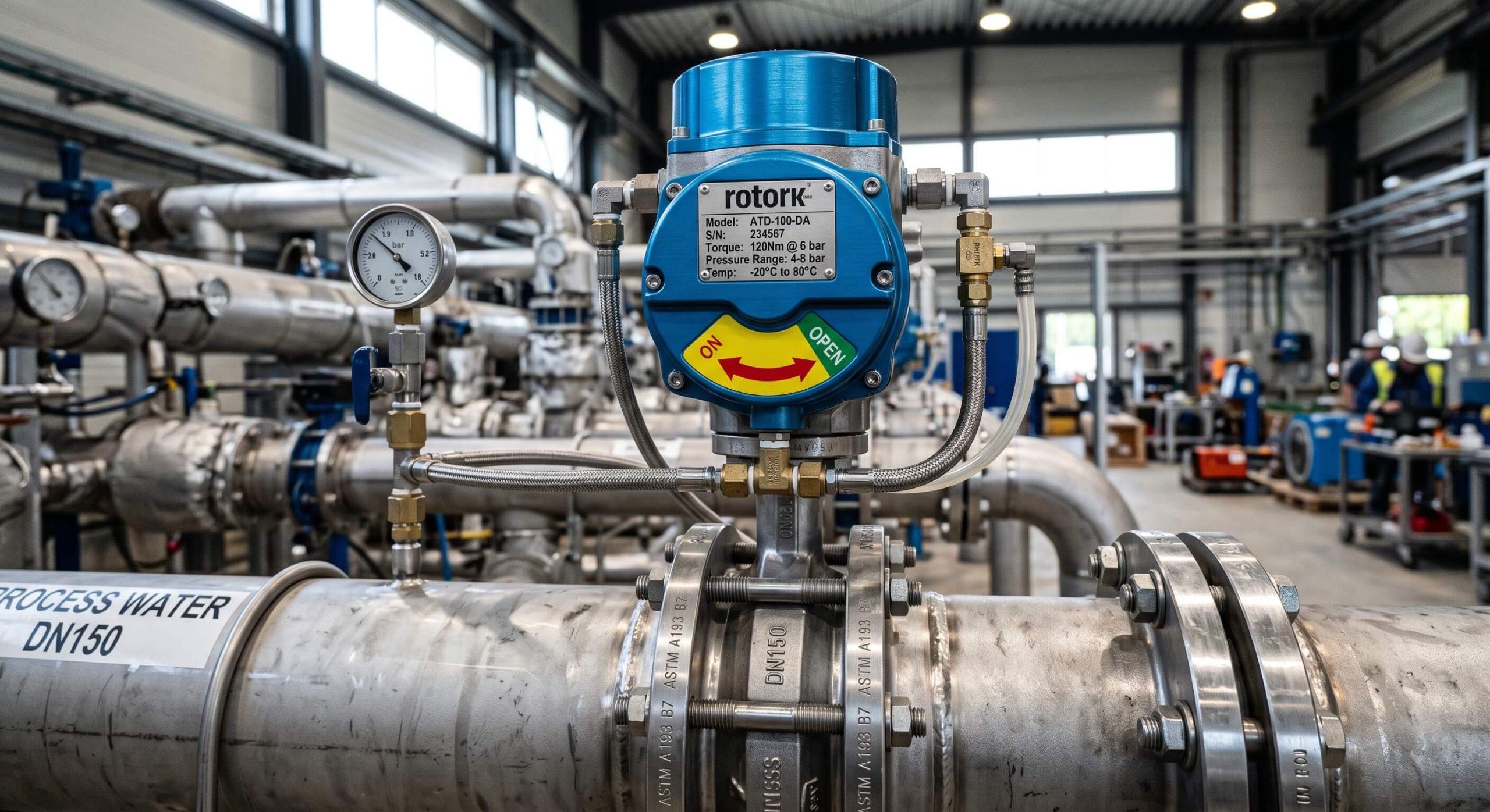
What components build a pneumatic actuator for butterfly valve?
Several machined metal parts assemble into one cohesive power unit. Manufacturing these devices involves precise engineering tolerances across multiple materials. A pneumatic actuator for butterfly valve contains modular elements designed for easy replacement. You can swap damaged pieces without discarding entire assemblies.
Central body housing
Extruded aluminum forms an incredibly rigid protective outer shell. Hard anodized coatings prevent external environmental corrosion effectively. It gets better, smooth internal cylinder walls reduce piston friction significantly.
Pistons and racks
Twin pistons move away from each other symmetrically during operation. Machined metal teeth engage central pinions flawlessly.
- Carbon steel racks provide strength
- Synthetic guide rings prevent wear
- O-rings seal pressurized chambers
Spring return cartridges
Pre-compressed springs sit securely inside end caps. They supply mechanical energy whenever air pressure vanishes unexpectedly. Listen to this, modular cartridge designs make field replacements incredibly safe for technicians.
Key Takeaway: High-quality internal components dictate overall machinery longevity under grueling factory conditions.
| Component | Material | Primary Function |
|---|---|---|
| Body | Extruded Aluminum | Houses internal moving parts |
| Piston | Die-cast Aluminum | Converts pressure into motion |
| Seals | Nitrile Rubber | Prevents gas leakage |
Examining material construction reveals why these automation tools survive aggressive industrial environments long-term.
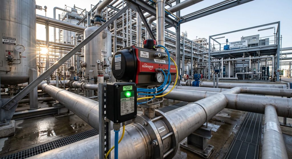
When to use a pneumatic actuator for butterfly valve?
Facilities deploy them whenever rapid, automated flow regulation becomes necessary. Certain industrial scenarios demand instantaneous liquid isolation protocols. A pneumatic actuator for butterfly valve thrives in fast-paced production lines. You should implement this technology when manual intervention poses safety risks.
Hazardous area applications
Explosive atmospheres restrict electrical equipment usage severely. Compressed gas systems generate zero ignition sparks during operation. Here is the deal, chemical refineries rely exclusively upon air-driven controls for fire prevention.
High-cycle processing
Batch manufacturing requires hundreds of valve cycles daily. Mechanical springs endure continuous flexing without losing tension easily.
- Packaging lines
- Beverage mixing tanks
- Pharmaceutical ingredient dosing
Emergency fail-safe situations
Critical cooling loops require guaranteed opening during power outages. Spring-return mechanisms move disks into safe positions automatically. But here’s the kicker, relying on gravity or batteries often fails during true emergencies.
Key Takeaway: Identifying correct application scenarios maximizes your operational efficiency while protecting vulnerable infrastructure.
| Scenario | Requirement | Solution |
|---|---|---|
| Explosive Zone | No electrical sparks | Purely air-driven operation |
| High Cycle | Millions of actuations | Rack and pinion mechanics |
| Power Failure | Guaranteed safe state | Spring return configuration |
Matching equipment capabilities against environmental demands guarantees successful long-term fluid management.
How to install a pneumatic actuator for butterfly valve?
Installation involves mounting hardware directly onto exposed valve stems securely. Proper alignment prevents uneven mechanical wear during rotational cycles. A pneumatic actuator for butterfly valve requires sturdy bolting against standard mounting pads. You must calibrate travel stops perfectly before initiating flow.
Mechanical mounting procedures
Brackets connect actuators toward valve bodies rigidly. Technicians align central drive shafts using specialized metal couplings. What’s the real story? Misaligned shafts cause severe binding, destroying internal bearings rapidly.
Pneumatic tubing connection
Polyurethane hoses route compressed gas into designated cylinder ports. Solenoid blocks mount directly against aluminum housings often.
- Cut tubing squarely
- Secure push-to-connect fittings
- Check for audible leaks
Setting travel limits
Adjustable bolts restrict maximum rotational angles accurately. Disks must stop exactly parallel against fluid streams. Ready for the good part? Fine-tuning these stops prevents premature rubber seat degradation drastically.
Key Takeaway: Methodical installation practices prevent early mechanical failures while securing optimal flow characteristics.
| Installation Step | Tool Required | Critical Check |
|---|---|---|
| Shaft Alignment | Dial Indicator | Zero lateral stress |
| Tube Fitting | Tube Cutter | Clean square cuts |
| Stop Adjustment | Wrench | Exact 90-degree rotation |
Following structured assembly protocols eliminates frustrating operational binding shortly after factory commissioning.
What limits a pneumatic actuator for butterfly valve?
Available compressor capacity and extreme temperatures restrict their operational effectiveness. Every mechanical system experiences specific physical performance boundaries. A pneumatic actuator for butterfly valve cannot function properly without consistent air supplies. You must recognize these limitations before designing complex fluid networks.
Temperature constraints
Standard rubber seals harden under freezing conditions rapidly. Extreme heat melts internal synthetic guide rings simultaneously. This is where it gets interesting, specialized Viton components extend temperature ranges considerably.
Air quality dependency
Compressors pumping wet air ruin internal metallic chambers quickly. Condensed moisture causes internal rust, seizing piston movements entirely.
- Install refrigerated air dryers
- Utilize micron filters
- Add lubricating mist systems
Torque output ceilings
Massive pipeline diameters require force exceeding standard pneumatic capabilities. Hydraulic systems become necessary for extremely large infrastructure projects. You might be wondering, how big is too big? Diameters exceeding forty inches generally require alternative power methods.
Key Takeaway: Respecting physical design limitations prevents catastrophic system failures during demanding industrial operations.
| Limitation | Cause | Mitigation Strategy |
|---|---|---|
| Temperature | Seal degradation | Upgrade to Viton seals |
| Air Quality | Moisture and dirt | Install filtration units |
| Max Torque | Cylinder size limits | Switch to hydraulic power |
Understanding operational boundaries helps engineers select appropriate automation technologies for specific environments.
How to test a pneumatic actuator for butterfly valve?
Testing involves cycling pressurized gas while monitoring rotational speeds and leakages. Rigorous evaluation guarantees equipment readiness before entering active service. A pneumatic actuator for butterfly valve undergoes strict bench testing protocols. You should verify all fail-safe mechanisms repeatedly under controlled conditions.
Bench cycling procedures
Technicians apply varying gas pressures while measuring output torque. Disks must rotate smoothly without any jerky movements. Truth be told, skipping bench tests leads directly toward expensive field replacements.
Leak detection methods
Soap solutions sprayed across housing joints reveal escaping gas bubbles. Pressure drop tests confirm internal piston seal integrity.
- Pressurize internal chambers
- Close supply valves
- Monitor gauge drops
Verifying fail-safe actions
Removing air supplies simulates sudden factory power losses realistically. Springs must snap mechanisms shut within specified timeframes. It gets better, electronic timers measure these emergency responses down into milliseconds.
Key Takeaway: Comprehensive pre-installation testing eliminates unexpected mechanical failures during critical production runs.
| Test Type | Objective | Acceptable Result |
|---|---|---|
| Cycle Test | Verify smooth motion | No binding or jerking |
| Leak Test | Check seal integrity | Zero pressure drop |
| Fail-Safe | Measure spring speed | Closes under 1 second |
Documenting test results creates valuable baseline data for future maintenance troubleshooting efforts.
How to maintain a pneumatic actuator for butterfly valve?
Routine maintenance requires regular lubrication and periodic seal replacements. Proactive care extends mechanical lifespans across decades of continuous service. A pneumatic actuator for butterfly valve needs clean air to function flawlessly. You can prevent sudden breakdowns by following scheduled inspection routines.
Preventative inspection schedules
Technicians should check external housings for visible corrosion monthly. Listening for subtle air hisses catches failing seals early. Think about it, minor leaks waste expensive compressor energy constantly.
Lubrication requirements
Factory grease degrades after millions of rotational cycles. Reapplying synthetic lubricants keeps metal gears turning smoothly.
- Disassemble end caps carefully
- Clean old degraded grease
- Apply fresh lithium compounds
Replacing worn soft goods
Rebuild kits contain fresh O-rings and synthetic guide pads. Swapping these inexpensive items restores factory-level performance completely. Listen to this, rebuilding takes mere minutes while saving thousands over buying replacements.
Key Takeaway: Implementing structured maintenance programs maximizes equipment uptime while protecting initial capital investments.
| Maintenance Task | Frequency | Benefit |
|---|---|---|
| Visual Inspection | Monthly | Catches external damage |
| Lubrication | Bi-Annually | Prevents gear wear |
| Seal Replacement | Every 3 Years | Restores full power |
Executing consistent upkeep routines prevents unexpected machinery paralysis during critical manufacturing quotas.
Wrapping Up
Upgrading pipeline automation solves unpredictable fluid surging and slow manual response times entirely. We provide rugged flow control hardware designed specifically for your demanding environments. Please contact us today for customized engineering solutions. Our brand stands firmly behind delivering absolute reliability when your facility needs it most.
Frequently Asked Questions
Q1: Can I use this mechanism outside in freezing weather?
Yes, but specific modifications remain necessary. Standard rubber seals harden in extreme cold, so you must install low-temperature silicone O-rings to prevent pressure leaks.
Q2: What’s the best way to prevent internal corrosion?
Installing a dedicated air filter regulator provides the highest protection level. This device strips moisture and dirt from the compressor lines before gas enters the cylinder.
Q3: How do I know if the internal springs are failing?
Slow closing speeds during a power loss indicate weak mechanical tension. If the disk takes longer than two seconds to shut, the cartridge requires immediate replacement.
Q4: Can I adjust the opening angle manually?
Yes, most units feature external travel stop bolts. Turning these steel screws limits piston movement, which restricts the maximum disk angle accurately.
Q5: What’s the best fail-safe configuration for toxic chemicals?
A fail-closed setup provides maximum environmental protection against spills. If your plant loses power, internal springs automatically force the pipeline shut to contain hazardous materials.