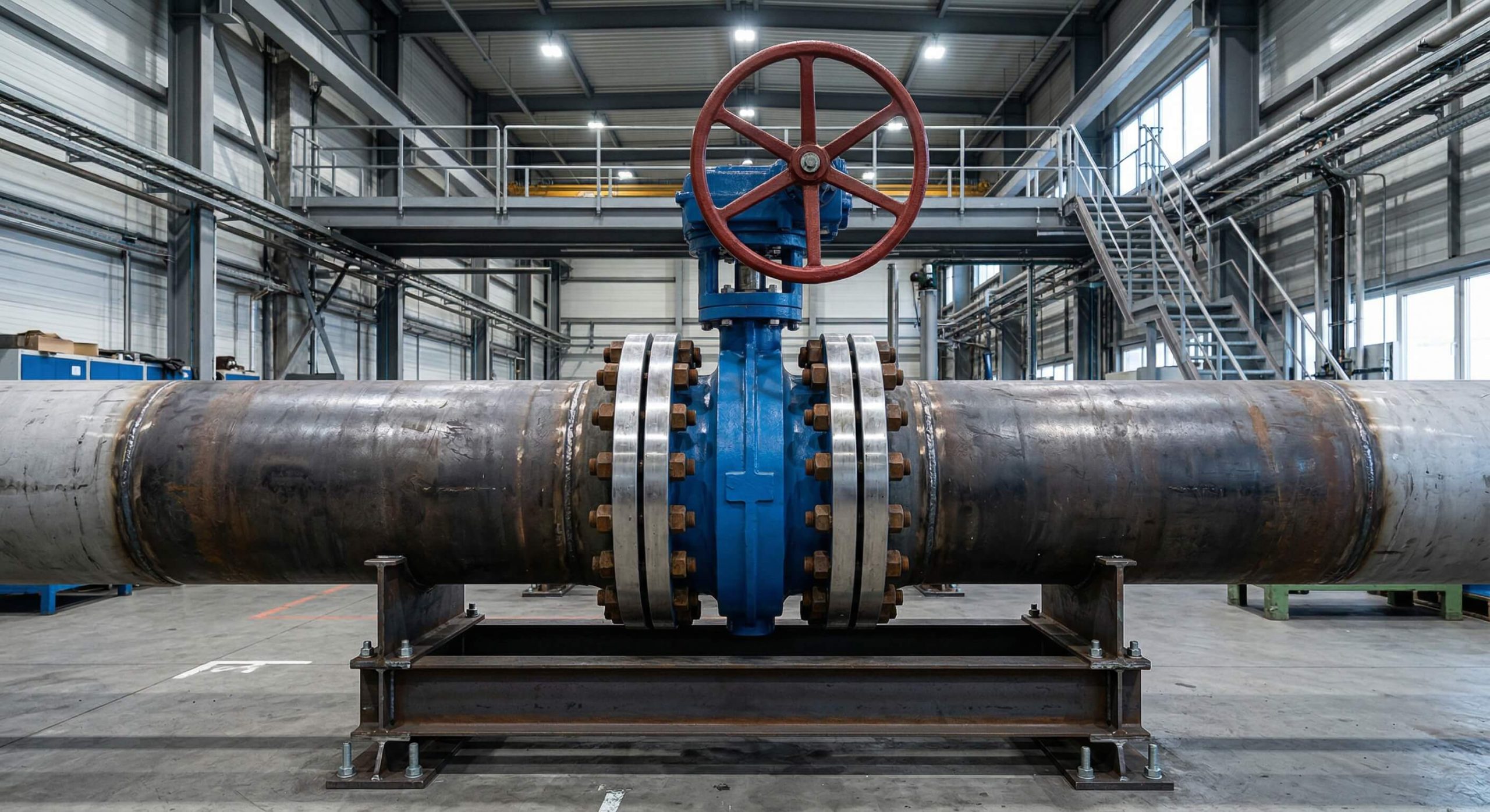
A butterfly valve regulates fluid flow through a quarter-turn mechanism where a circular disc rotates 90 degrees around a central shaft to either obstruct or permit passage.
Miscalculating flow dynamics in complex industrial pipelines often leads to catastrophic pressure surges and premature component failure. You might find yourself dealing with constant leaks and expensive maintenance cycles if you choose the wrong valve geometry for your specific media. Fortunately, using a visual technical guide provides the clarity you need to optimize your infrastructure and ensure long-term stability.
Mastering these systems requires a deep dive into the butterfly valve animation to visualize the internal mechanical interactions. This guide simplifies the complex physics of quarter-turn technology for your facility.
How does a butterfly valve animation show flow?
Flow is demonstrated by the 90-degree rotation of a disc that moves from a position parallel to the pipe to one that is perpendicular. When you watch a butterfly valve animation, you can see how the circular plate acts as a gateway for the media. This butterfly valve animation reveals how the disc remains in the flow stream even when fully opened.
Does the disc angle impact pressure?
The disc angle directly influences the pressure drop across the system as it rotates. At 90 degrees, the obstruction is minimal, yet the permanent presence of the stem and disc still creates turbulence.
Look:
- 0 degrees: Fully closed, zero flow.
- 45 degrees: Moderate throttling and turbulence.
- 90 degrees: Maximum flow with minor pressure drop.
Key Takeaway: The visual representation confirms that the disc never leaves the flow path, creating a permanent K-factor.
The following data outlines the relationship between rotation and flow capacity.
| Rotation Angle | Flow Status | Pressure Drop |
|---|---|---|
| 0° | Blocked | Infinite |
| 30° | Throttling | High |
| 90° | Fully Open | Low |
Why watch a butterfly valve animation for principles?
Technical animations allow you to observe how torque is transferred from the actuator through the stem to the disc in real-time. By studying a butterfly valve animation, you gain an intuitive understanding of the mechanical stress points that are invisible during standard operation. This perspective is vital for engineers designing high-pressure systems.
Is torque transfer visible?
You can see the direct mechanical link between the stem and the disc center. The animation highlights how force is distributed across the disc surface as it fights against the media pressure.
Think about it.
- Stem rotation translates force.
- Disc pivot provides the seal.
- Actuators provide the necessary leverage.
Key Takeaway: Visualizing internal mechanics helps in calculating the exact torque requirements for automation.
This guide helps you compare different mechanical stress profiles.
| Component | Role | Common Stress |
|---|---|---|
| Stem | Torque Transfer | Torsional Shear |
| Disc | Flow Regulation | Bending Force |
| Seat | Sealing | Compression Set |
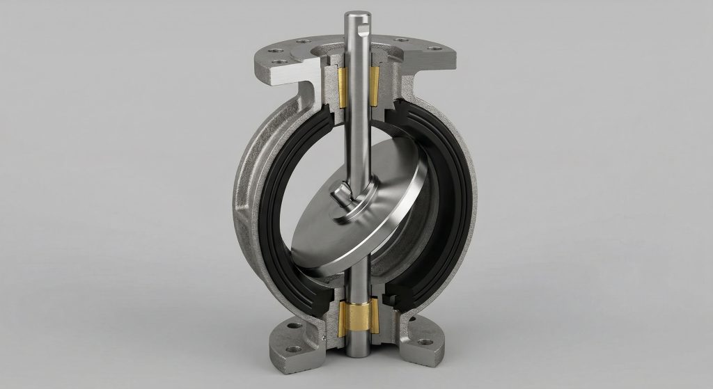
Can a butterfly valve animation explain the disc?
The disc is the primary regulating element that pivots on a central axis to control the volume of fluid passing through the valve. A butterfly valve animation clearly identifies the disc’s movement as a “butterfly” wing action. This butterfly valve animation simplifies the understanding of the thin profile required for efficiency.
What is the parallel position?
In the parallel position, the disc is aligned with the flow to provide the least amount of resistance. This state allows for the highest flow velocity while maintaining system stability.
Here is the thing:
- Thin disc design reduces drag.
- Central shaft provides structural support.
- Symmetrical wings balance the load.
Key Takeaway: The disc’s geometry is optimized to balance structural integrity with flow efficiency.
Review the disc variations typically seen in industrial designs.
| Disc Type | Material | Application |
|---|---|---|
| Concentric | Ductile Iron | Water Systems |
| Eccentric | Stainless Steel | High Pressure |
| Lined | PTFE | Corrosive Media |
What does a butterfly valve animation reveal on seats?
The seat provides the sealing interface where the disc makes contact to stop the flow completely. Observing a butterfly valve animation shows the “wiping” action as the disc edge slides into the resilient seat. This butterfly valve animation highlights how debris is pushed aside to ensure a tight shut-off.
How do resilient seats seal?
Resilient seats use elastic materials like EPDM or NBR to compress against the disc. The animation displays how the material deforms slightly to create a bubble-tight seal under pressure.
But that’s not all.
- Soft seats absorb vibrations.
- Compression ensures zero leakage.
- Replaceable designs reduce costs.
Key Takeaway: Seat material selection is the most critical factor for achieving a zero-leakage rating in your system.
Use this table to select the right seat material for your temperature range.
| Seat Material | Temp Range | Media Type |
|---|---|---|
| EPDM | -20 to 120°C | Water/Steam |
| PTFE | -30 to 200°C | Chemicals |
| Metal | Up to 600°C | High Heat |
Does a butterfly valve animation help choose actuators?
Actuator selection depends on the effort required to rotate the disc against the internal line pressure. A butterfly valve animation contrasts the speed of a manual lever against the precision of a worm gear operator. Seeing these components in motion helps you decide between manual control and automated performance.
Lever or gear?
Manual levers are best for smaller valves where quick operation is the priority. Gear operators are necessary for large diameters where the torque required exceeds human capability.
Why does this matter?
- Levers offer 90-degree speed.
- Gears provide mechanical advantage.
- Automation allows remote monitoring.
Key Takeaway: The animation proves that larger valves require gear assistance to prevent accidental slamming or failure.
Compare the three primary actuation methods for industrial applications.
| Actuation | Power Source | Best Use Case |
|---|---|---|
| Manual | Human Force | Low Frequency |
| Pneumatic | Compressed Air | Rapid Cycles |
| Electric | Motorized | Precision Control |
How does a butterfly valve animation clarify offsets?
Offset designs move the stem away from the center of the disc to reduce friction and wear on the seat. Watching a butterfly valve animation shows how the disc “cams” into the seat rather than scraping against it. This butterfly valve animation is essential for understanding high-performance valve technology.
Why use triple offsets?
Triple offsets use three separate eccentricities to create a frictionless conical sealing path. The animation demonstrates that contact only occurs at the very last degree of closure, extending the life of the metal seat.
Listen:
- First offset: Stem behind disc.
- Second offset: Stem off-center.
- Third offset: Conical seal geometry.
Key Takeaway: Offset technology is the standard for high-temperature and high-pressure industrial environments.
Here is a comparison of offset performance levels.
| Design | Friction | Leakage Class |
|---|---|---|
| Concentric | High | Class VI |
| Double Offset | Low | Class VI |
| Triple Offset | Zero | Zero Leakage |
Is a butterfly valve animation best for maintenance?
Maintenance teams use animations to identify potential failure points before they lead to a system shutdown. A butterfly valve animation helps you visualize where stem packing might leak or where the seat might erode. This butterfly valve animation serves as a training tool for identifying early warning signs.
Can you spot wear?
Visual simulations show how a worn disc edge fails to compress the seat uniformly. You can observe how misaligned stems cause uneven torque and accelerated component degradation.
You see,
- Vibration leads to stem wear.
- Erosion thins the disc edge.
- Packing leaks are often visible.
Key Takeaway: Understanding the mechanical movement allows for more accurate predictive maintenance schedules.
Check these common failure modes against their visual indicators.
| Problem | Visual Sign | Solution |
|---|---|---|
| Seat Erosion | Flow bypass | Replace Seat |
| Stem Shear | No rotation | Replace Stem |
| Packing Leak | External fluid | Tighten Nut |
Can a butterfly valve animation solve pressure drop?
Pressure drop occurs because the disc remains in the flow path even when the valve is fully open. An engineer studying a butterfly valve animation can calculate the K-factor by observing the turbulence patterns created by the disc. This butterfly valve animation helps in selecting the correct orifice size to minimize energy loss.
Does sizing matter?
Proper sizing ensures that the valve operates within its optimal Cv range to prevent cavitation. The animation highlights why an oversized valve leads to unstable flow and “fluttering” during throttling.
Best of all?
- Smaller footprint saves space.
- Lighter weight reduces support needs.
- Efficient design lowers energy bills.
Key Takeaway: Minimizing pressure drop requires a precise match between valve diameter and flow velocity.
Refer to this guide for standard Cv values at full opening.
| Valve Size | Typical Cv | Pressure Drop (PSI) |
|---|---|---|
| 4 Inch | 600 | 0.5 |
| 8 Inch | 2500 | 0.4 |
| 12 Inch | 5800 | 0.3 |
Will a butterfly valve animation show sealing types?
Sealing types range from soft resilient seats to hard metal-to-metal interfaces for extreme conditions. By reviewing a butterfly valve animation, you can see how different seal designs react to thermal expansion and high pressure. This butterfly valve animation differentiates between bidirectional and unidirectional sealing capabilities.
Metal vs Soft?
Metal seats are used for steam and high-heat applications where soft materials would melt. Soft seats are preferred for low-temperature liquids where a bubble-tight seal is required.
Now,
- Metal seats resist fire.
- Soft seats prevent leakage.
- Hybrid seals offer both.
Key Takeaway: The sealing mechanism must be matched to the chemical and thermal properties of your media.
This table compares sealing standards for industrial valves.
| Seal Type | Standard | Max Temp |
|---|---|---|
| Soft | API 598 | 200°C |
| Metal | ANSI B16.34 | 600°C |
| Lined | ISO 5208 | 150°C |
Where to find a butterfly valve animation for guides?
You can find comprehensive visual guides and technical data on the main product pages of industrial manufacturers. Referencing a butterfly valve animation allows you to verify that the connection type—wafer, lug, or flanged—fits your piping layout. This butterfly valve animation ensures that you select the right configuration for your specific installation environment.
Selection checklist?
Before finalizing your order, you should verify the pressure rating, temperature limits, and seat compatibility. The animation helps confirm that the actuator has enough clearance in tight mechanical rooms.
It gets better:
- Wafer saves on flange bolts.
- Lug allows dead-end service.
- Flanged offers maximum strength.
Key Takeaway: Visualizing the installation footprint prevents costly errors during the field implementation phase.
Use this checklist for your final procurement review.
| Feature | Requirement | Verified |
|---|---|---|
| Connection | Wafer/Lug/Flange | [ ] |
| Pressure | PN10/PN16/150# | [ ] |
| Media | Water/Gas/Chem | [ ] |
Conclusion
Mastering the working principles of quarter-turn technology is essential for maintaining a safe and efficient industrial operation. By utilizing a butterfly valve animation, you eliminate the guesswork from selection and ensure your systems are built for long-term reliability. We solve the common problems of leakage and pressure instability by providing high-performance solutions engineered for the most demanding environments. Our vision is to empower global industries with flow control technology that is both durable and easy to maintain. If you are ready to upgrade your facility, contact us today for a customized consultation and technical support.
Frequently Asked Questions
Can I use a butterfly valve for high-pressure steam?
Yes, but you must select a triple offset design with a metal-to-metal seat to handle the high temperatures and pressures without seal failure.
What’s the best seat material for abrasive slurries?
A resilient seat made of reinforced polyurethane or specialized EPDM is usually best, as it can withstand the impact of suspended solids during operation.
Can I install a butterfly valve in a vertical pipe?
Yes, you can install them in any orientation, though placing the stem horizontally is recommended to prevent debris from settling in the shaft bearings.
What’s the best way to prevent water hammer?
The best way is to use a gear operator or a slow-closing pneumatic actuator to ensure the disc doesn’t slam shut too quickly against the flow.
Can I replace the seat without buying a new valve?
Most concentric and high-performance designs feature replaceable seats, allowing you to perform maintenance without removing the entire valve body from the line.