You make a butterfly valve by casting a specialized metal body, machining precision components like the disc and stem, and assembling them with a resilient or metal seat for airtight sealing. You often face the risk of costly system failures and leaks when using poorly manufactured valves that cannot withstand high pressure. These frequent maintenance headaches agitate your operational budget and lead to significant project delays. By mastering the butterfly valve manufacturing process, you can identify high-quality suppliers that ensure long-term reliability and peak efficiency.
Which materials are selected for production?
The butterfly valve manufacturing process begins with selecting certified raw materials like ductile iron, stainless steel, or carbon steel to match specific industrial conditions. You must ensure the chosen alloys possess the required tensile strength and corrosion resistance for your media. High-quality manufacturers source these metals from verified mills to prevent structural defects during the casting stage.
Metal Body Selection
You generally choose ductile iron for general water applications or stainless steel 316L for corrosive chemical environments. Carbon steel is often preferred for high-temperature steam systems due to its superior thermal stability.
- Ductile Iron (ASTM A536)
- Stainless Steel (CF8M)
- Carbon Steel (WCB)
Seat Elastomer Options
Your selection of seat material is critical because it determines the valve’s sealing temperature and chemical compatibility. Resilient materials are molded to fit the inner bore precisely.
- EPDM for water and wastewater.
- PTFE for aggressive chemicals.
- NBR for petroleum products.
Key Takeaway
Material integrity is the foundation of valve longevity; using the wrong alloy can lead to premature failure in corrosive environments.
| Material Component | Common Grade | Ideal Application |
|---|---|---|
| Body | Ductile Iron | Water Treatment |
| Disc | Stainless 316 | Marine/Chemical |
| Seat | PTFE | Acidic Media |
How does the casting process shape the body?
The butterfly valve manufacturing process utilizes sand casting or investment casting to create the complex geometry of the valve body and disc. You rely on precision molds to ensure the raw castings have the correct wall thickness and internal dimensions. Once the molten metal is poured and cooled, the castings are cleaned and shot-blasted to remove impurities.
Pattern and Mold Creation
Engineers design specialized patterns that account for metal shrinkage during the cooling phase. These patterns create the negative space in the mold that eventually holds the molten alloy.
- CAD-based design patterns.
- High-strength sand molds.
- Precision core placement.
Solidification and Cleaning
You must control the cooling rate carefully to avoid internal stresses or porosity that could weaken the valve structure. After cooling, the “shakeout” process removes the sand, followed by trimming excess metal.
- Controlled cooling cycles.
- Robotic shot blasting.
- Visual surface inspection.
Key Takeaway
Quality casting reduces the amount of expensive machining required and ensures the valve can withstand its rated working pressure.
| Casting Method | Precision Level | Best For |
|---|---|---|
| Sand Casting | Standard | Large diameter valves |
| Investment Casting | High | Small, complex discs |
| Shell Molding | Moderate | Batch production |
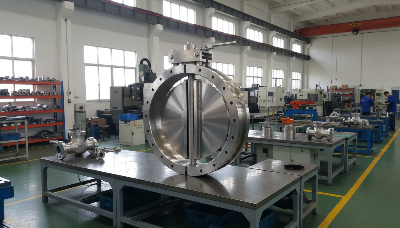
Why is precision machining critical for parts?
Precision machining is essential in the butterfly valve manufacturing process because it creates the exact tolerances needed for the disc to rotate smoothly within the seat. You use CNC machines to mill the flange faces and turn the stem holes to within fractions of a millimeter. This extreme accuracy ensures that the finished valve will be interchangeable and easy to install.
CNC Body Turning
You utilize CNC lathes to finish the internal bore where the seat will eventually reside. This step ensures a perfectly circular profile that prevents uneven wear on the rubber or metal seal.
- Bore finishing for seat fit.
- Flange face serration.
- Drilled mounting pads.
Stem and Disc Milling
The disc must be machined to a thin, aerodynamic profile to minimize flow resistance while maintaining structural strength. You also machine the stem with specific flats or keyways to connect securely to the actuator.
- Disc edge polishing.
- Stem hole alignment.
- Keyway precision cutting.
Key Takeaway
Accurate machining prevents “torque spikes” during operation, which can damage actuators and cause inconsistent flow control.
| Machine Tool | Operation | Target Feature |
|---|---|---|
| CNC Lathe | Internal Turning | Seat Sealing Surface |
| Milling Machine | Pad Facing | Actuator Mounting |
| Grinding Machine | Edge Polishing | Disc Sealing Radius |
How is the valve seat installed correctly?
Installing the seat is a delicate part of the butterfly valve manufacturing process that requires lubricating the elastomer and pressing it into the machined valve body. You must ensure the seat holes align perfectly with the stem holes to allow for the shaft’s insertion. A misaligned seat will lead to immediate leakage or excessive operation torque.
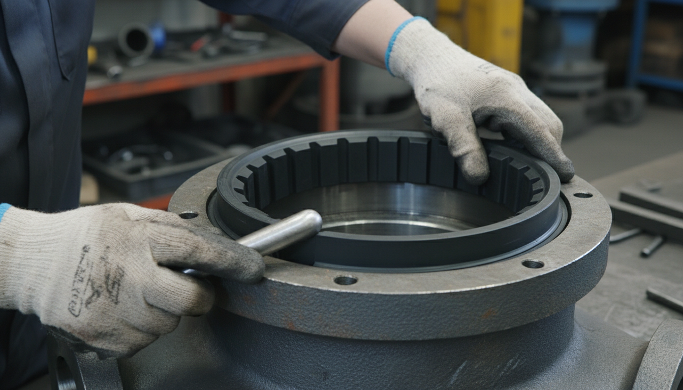
Soft Seat Compression
For wafer or lug types, you often apply a thin layer of silicone lubricant to help the seat slide into the body groove. You then use a small mallet or press to tap the seat until it is fully embedded.
- Lubrication application.
- Alignment check.
- Uniform pressing.
Hard-Backed Seat Fitting
If you are working with hard-backed seats, the installation typically requires a more powerful hydraulic press to force the rigid component into place. This design provides better stability for high-velocity flow and vacuum services.
- Hydraulic press utilization.
- Final seating inspection.
- Bore concentricity test.
Key Takeaway
The seat installation phase determines whether the valve will achieve a bubble-tight seal at low and high pressures.
| Seat Type | Installation Tool | Major Benefit |
|---|---|---|
| Soft-Seated | Manual/Mallet | Ease of replacement |
| Hard-Backed | Hydraulic Press | Vacuum resistance |
| Metal-Seated | Specialized Jig | High-temp durability |
What happens during disc and stem assembly?
The butterfly valve manufacturing process moves to the assembly stage where the disc is positioned inside the seat and the stem is inserted through the body. You must ensure the stem passes through the disc center accurately to maintain a balanced rotation. Depending on the design, you might use pins, bolts, or a splined connection to join the stem to the disc.
Stem Insertion Techniques
You insert the stem from the top flange, passing through the upper bushing, the disc, and finally the lower bushing. This creates a “through-axis” that supports the disc’s weight and resists the force of the flowing media.
- Bushing installation.
- Stem alignment.
- O-ring sealing.
Disc-to-Stem Fastening
You secure the connection using taper pins or a “dry-shaft” design where the disc has a squared or splined internal hole. This prevents the disc from spinning freely on the shaft when you turn the handle.
- Taper pin driving.
- Spline engagement.
- Retention screw tightening.
Key Takeaway
A secure disc-to-stem connection is vital; any “play” in the joint will result in poor control accuracy and potential vibration.
| Connection Type | Pros | Cons |
|---|---|---|
| Taper Pinned | Very high strength | Harder to disassemble |
| Square Drive | Easy maintenance | Torque limits |
| Splined Shaft | Zero backlash | Higher machining cost |
How is pressure testing performed for safety?
Pressure testing is the most critical quality control step in the butterfly valve manufacturing process to verify the integrity of the seals and body. You perform both a shell test to check for body leaks and a seat test to ensure zero leakage when the valve is closed. Every valve must pass these tests according to standards like API 598 or EN 12266 before leaving the factory.
Hydrostatic Shell Testing
You fill the valve body with water and apply pressure at 1.5 times the rated working limit. You inspect the exterior of the casting for any “sweating” or cracks that would indicate a structural flaw.
- High-pressure water pumps.
- 1.5x rating application.
- Visual inspection.
Low-Pressure Air Testing
You also perform a seat leakage test using air at a lower pressure to detect even the smallest pathways for fluid escape. Check this out: bubble-tight performance is the industry gold standard for resilient-seated valves.
- Air bubble detection.
- Seal surface check.
- Torque verification.
Key Takeaway
Testing is non-negotiable; it is your final guarantee that the valve will perform safely under real-world pipeline conditions.
| Test Type | Test Media | Pressure Level |
|---|---|---|
| Shell Test | Water | 1.5x Working Pressure |
| Seat Test | Water/Air | 1.1x Working Pressure |
| Torque Test | Mechanical | Operating Limit |
Which drivers are installed for operation?
The butterfly valve manufacturing process concludes with the installation of a manual handle, gear box, or automated actuator. You choose the driver based on the valve size and the frequency of operation required by your system. The mounting pad on the top flange allows you to switch between these drivers without disassembling the valve internals.
Manual Lever and Gearboxes
For smaller valves, you usually install a simple ten-position locking handle for quick manual control. Larger valves require a worm gearbox to provide the mechanical advantage needed to overcome high operating torque.
- Lever with notch plate.
- Worm gear drive.
- Handwheel installation.
Automated Actuator Mounting
If your system requires remote control, you mount a pneumatic, electric, or hydraulic actuator onto the ISO 5211 pad. You must calibrate the limit switches to ensure the valve opens and closes to the exact 90-degree points.
- Pneumatic cylinders.
- Electric motor drives.
- Limit switch setting.
Key Takeaway
Choosing the right driver ensures that operators can manage the flow safely and efficiently without excessive physical effort.
| Driver Type | Best Valve Size | Operation Speed |
|---|---|---|
| Manual Lever | DN50 – DN200 | Very Fast |
| Worm Gear | DN250 – DN1200 | Slow/Precise |
| Pneumatic | All Sizes | Rapid/Remote |
Why is coating and painting necessary?
Applying a protective coating is a vital step in the butterfly valve manufacturing process to prevent external atmospheric corrosion. You typically use fusion-bonded epoxy (FBE) or high-quality liquid paints to create a durable barrier against moisture and chemicals. This coating not only protects the metal but also provides a professional finish that indicates the valve’s service type.
Surface Pre-treatment
You must thoroughly clean the valve body using sandblasting or chemical degreasing to ensure the paint adheres properly. Without this step, the coating will peel or flake off shortly after the valve is installed in the field.
- Sandblasting to Sa 2.5.
- Grease removal.
- Dust cleaning.
Coating Application Methods
You often use electrostatic spray booths for epoxy powders, which are then cured in a high-temperature oven for a hard finish. For custom colors or field repairs, liquid polyurethane or alkyd paints are applied using professional spray guns.
- Fusion-bonded epoxy.
- Heat curing cycles.
- Thickness measurement.
Key Takeaway
A robust coating extends the service life of the valve body by decades, especially in outdoor or coastal environments.
| Coating Type | Application Method | Environment |
|---|---|---|
| FBE Powder | Electrostatic Spray | Highly Corrosive |
| Polyurethane | Liquid Spray | UV Resistant |
| Zinc Primer | Brush/Spray | Marine Basecoat |
How is quality assurance managed throughout?
Quality assurance in the butterfly valve manufacturing process involves rigorous documentation and inspection at every single stage of production. You keep detailed records of material heat numbers, machining dimensions, and pressure test results for every batch. This traceability allows you to verify that the valves meet international certifications like ISO 9001 or CE.
Material Traceability
You track the “Heat Number” of the raw metal from the foundry to the final finished product. This ensures that if a material defect is discovered later, you can identify every valve made from that specific batch of metal.
- Heat number tracking.
- MTC (Material Test Certificate).
- Chemical analysis.
Final Dimensional Inspection
Before packaging, you perform a final check of the flange-to-flange distance and the bolt hole alignment. Here is the deal: if these dimensions are wrong, the valve simply won’t fit into the pipeline during commissioning.
- Face-to-face check.
- Flange alignment.
- Nameplate verification.
Key Takeaway
Rigorous QA processes minimize the risk of “dead on arrival” products and protect your reputation as a reliable engineer.
| QA Document | Content | Purpose |
|---|---|---|
| MTC | Chemical/Mechanical Data | Material Verification |
| Test Report | Hydro/Air Results | Safety Guarantee |
| Certificate of Origin | Factory Details | Compliance |
How should you package and ship valves?
The final step of the butterfly valve manufacturing process is specialized packaging designed to prevent damage during international transit. You use plastic end caps to protect the sealing faces and heavy-duty wooden crates to prevent the valves from shifting. Proper labeling ensures that the valves are handled correctly and reach the right department at your facility.
Protective Wrapping and Capping
You place plastic covers over the flange faces to prevent scratches and keep dust out of the internal bore. For larger shipments, you might also wrap the entire valve in shrink-wrap to protect it from sea-salt corrosion during shipping.
- Flange end caps.
- Shrink-wrap protection.
- Desiccant packs.
Crating and Labeling
You secure the valves inside reinforced plywood boxes with internal bracing to prevent movement during transport. Every box is clearly labeled with the part number, quantity, and weight to facilitate smooth logistics and customs clearance.
- ISPM 15 wooden crates.
- Internal bracing.
- Shipping labels.
Key Takeaway
Professional packaging ensures that the high-quality valve you manufactured arrives in perfect condition, ready for immediate installation.
| Packing Element | Material | Protection Goal |
|---|---|---|
| End Caps | Plastic/Polyethylene | Sealing Surface |
| Crate | Reinforced Plywood | Impact Resistance |
| Inner Lining | Waterproof Paper | Moisture Control |
Strategic Summary of Butterfly Valve Manufacturing
Industrial butterfly valve production is a sophisticated journey from raw alloy to a precision-engineered control device. By following these steps, factories ensure that every unit can handle the intense demands of modern piping systems. If you are ready to upgrade your fluid control systems with high-performance hardware, we invite you to contact us today for a technical consultation.
Frequently Asked Questions
Can I customize the coating color for my specific project requirements?
Yes, most manufacturers offer custom RAL colors for epoxy or liquid coatings to help you identify different pipelines, such as blue for water or red for fire protection.
What’s the best way to verify the material quality of a new valve?
You should always request a 3.1 Material Test Certificate (MTC) which provides the chemical breakdown and mechanical properties of the exact batch of metal used for your valve.
Can I automate a manual butterfly valve after it has been installed?
Absolutely, as long as the valve has a standard ISO 5211 mounting pad, you can remove the manual lever and install a pneumatic or electric actuator at any time.
What’s the best method for testing the seal of a high-pressure valve?
The industry standard is a low-pressure air test for bubble-tightness followed by a high-pressure hydrostatic test to ensure the seals don’t fail under extreme load.
Can I use a standard butterfly valve for vacuum service?
Standard valves can work, but for high-vacuum applications, you should specifically request a hard-backed seat or a double-offset design to prevent seat deformation.