Selecting a trunnion ball valve vs floating ball valve configuration depends primarily on the pressure rating, pipeline size, and sealing requirements of your process system. For pipeline designers and procurement managers, evaluating the mechanical trade-offs of a trunnion ball valve vs floating design is a critical milestone in optimizing fluid processing networks. Choosing the wrong configuration can result in accelerated seat wear, elevated operating torque that stalls actuators, and severe piping safety hazards. To mitigate these pre-commissioning risks and avoid unplanned downtime, process engineers must analyze the physical differences between these two rotary valve types. This guide provides a detailed comparative analysis of these configurations, helping engineers specify high-performance ball valves that deliver reliable performance, longevity, and regulatory compliance.
Core Mechanical Design and Working Principles
Floating Design: Mechanical Suspension and Downstream Movement
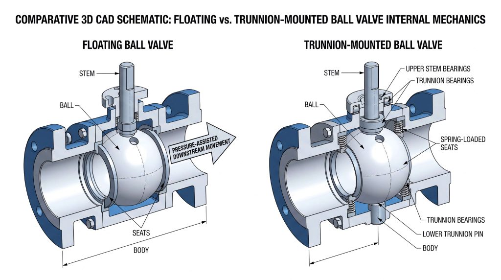
In a floating ball valve, the ball is suspended within a pair of polymeric or elastomeric seats, with no permanent anchor supporting its lower hemisphere. The valve stem is slotted into a rectangular recess at the top of the ball. This slot-and-key connection allows the ball a degree of free physical movement along the flow axis of the pipeline.
When the valve is rotated to the closed position and subjected to upstream line pressure, the fluid forces the ball downstream. This movement causes the ball to slide along the axis, compressing the downstream seat against the valve body wall to form a positive, pressure-assisted seal. This floating mechanism relies entirely on the process medium’s hydraulic force to maintain seat contact, making it a highly elegant, self-adjusting solution for low-pressure systems.
Trunnion Design: Fixed Axis and Pivot Pin Support
A trunnion-mounted ball valve fixes the ball along a rigid vertical axis using an upper stem and a lower pivot pin, commonly referred to as the trunnion. This dual-shaft design completely prevents the ball from shifting downstream under pressure. Instead, the tremendous hydrostatic thrust force generated by high-pressure process media is absorbed directly by high-load sleeve bearings, typically fabricated from bronze, metal-backed PTFE, or high-performance alloys.
Because the ball itself cannot move, the sealing action is performed by independent, spring-loaded seat assemblies. These seat rings are engineered with built-in wave springs or coil springs that continuously push the seat face against the ball. When upstream pressure enters the valve, it acts on the back of the floating seat rings, forcing them tightly against the fixed ball to establish a positive seal on both the upstream and downstream sides simultaneously.
Sealing Dynamics and Pressure Isolation Capacity
Upstream vs Downstream Sealing Behavior under Load
The downstream sealing action of a floating ball valve is highly effective, but it exhibits clear limitations when subjected to low-pressure or vacuum services. After a certain amount of seat wear occurs, the lack of sufficient differential line pressure in low-pressure lines can prevent the ball from compressing the downstream seat enough to stop bypass. Consequently, floating valves are generally restricted to applications where a minimum operating pressure is consistently maintained.
Trunnion-mounted valves utilize an upstream-sealing mechanism that performs reliably across the entire pressure spectrum, from deep vacuum to high-pressure transients. Because the spring-loaded seat rings are continuously energized against the fixed ball, they do not rely on high differential pressure to initiate a seal. The initial mechanical spring preload maintains tight contact at near-zero line pressures, while rising upstream pressures supplement this force by acting on the piston-effect area behind the seat ring.
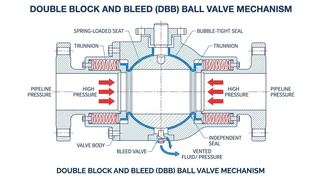
Double Block and Bleed (DBB) Isolation Capability
For critical process loops requiring strict safety isolation, trunnion-mounted valves offer a major advantage through Double Block and Bleed (DBB) capabilities. Because both the upstream and downstream seats of a trunnion valve seal independently against the fixed ball, the valve can block pressure from both directions simultaneously. By opening a bleed valve connected to the center body cavity, operators can drain trapped fluid and verify that no process media is bypassing either seat.
Implementing true DBB isolation in a standard floating ball valve is structurally impossible. Because a floating valve relies on the ball shifting downstream to compress a single seat, it cannot seal both upstream and downstream sides at the same time. While a floating valve provides excellent bi-directional flow shutoff, it only seals on one side at any given moment, making it unsuitable for safety-critical isolation manifolds that mandate verified cavity bleeding. In contrast, many heavy-duty gate valves or double-eccentric isolation valves must be specified if bi-directional dual-seat sealing is required in non-rotary designs.
Seat Wear Performance and Material Degradation
Soft Seat Deformation under Downstream Loads
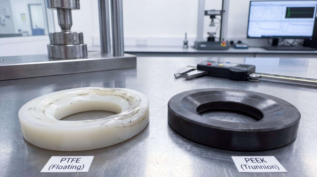
In a floating configuration, the downstream seat bears the entire hydraulic force of the process medium acting on the cross-sectional area of the ball. Under high-pressure conditions, such as ASME Class 300 or Class 600 systems, this concentrated thrust force can cause thermoplastic seats made of polytetrafluoroethylene (PTFE) or reinforced PTFE (RPTFE) to deform, undergo plastic deformation, or experience “cold flow” extrusion.
This mechanical limitation directly restricts the physical size of floating ball valves to typically DN200 (8 inches) or smaller. If a floating valve is built larger, the massive weight of the ball combined with high differential pressures would quickly crush the soft polymer seats. Over time, uneven load distribution during high-cycle opening and closing operations accelerates localized seat erosion, eventually leading to seat tears and internal bypass.
Spring-Energized Trunnion Seats and Wear Mitigation
Trunnion-mounted configurations bypass this mechanical failure mode by transferring all hydraulic thrust loads directly to the upper and lower stem bearings. The soft polymeric or metal seat rings are subjected only to the uniform contact force exerted by the backing springs and the localized piston-area pressure. This uniform distribution of contact pressure prevents seat deformation and eliminates the risk of cold flow extrusion even at Class 1500 or Class 2500 pressure ratings.
By isolating the seats from the ball’s mechanical load, trunnion designs allow the use of more robust, high-performance sealing materials, including Polyetheretherketone (PEEK), Devlon, Kel-F, or metal-to-metal seat faces with tungsten carbide coatings. This mechanical versatility significantly reduces friction coefficients, minimizes seat wear, and extends the operational lifespan of valves installed in aggressive slurry lines, high-temperature utility loops, and highly corrosive systems within chemical processing plants.
Actuation Torque Profiles and Energy Consumption
Operating Torque Escalation in Floating Configurations
Operating torque in a ball valve is primarily generated by the friction between the rotating ball and the stationary seat faces, stem packing resistance, and bearing friction. In a floating ball valve, because the ball is pressed hard against the downstream seat by line pressure, the operating torque is directly proportional to the differential pressure. At high differential pressures, the breakout torque required to open the valve rises exponentially, which can lead to rapid seat wear and premature packing fatigue.
For trunnion-mounted valves, the operating torque remains relatively flat and predictable across the entire pressure envelope. Because the trunnion bearings absorb the mechanical loads, the ball rotates smoothly on its fixed axis without shifting into the downstream seat. The only seat friction generated is from the controlled spring preloads and the upstream pressure acting on the seat ring’s limited piston area, resulting in a much lower torque curve than a floating valve of identical size and class.
Lower, Stable Torque in Pivot-Supported Designs
The difference in breakout torque has a direct financial impact on the overall automated valve package cost. When sizing actuators for large floating ball valves, piping design engineers are often forced to specify oversized pneumatic cylinder actuators or high-torque electric gearboxes to overcome high breakout torque. These oversized actuators increase the physical footprint of the valve assembly, require heavier pipe support structures, and substantially inflate initial capital expenditures.
By specifying a low-torque, trunnion-mounted configuration, engineers can pair the valve with a significantly smaller, more compact pneumatic or electric actuator. This integration reduces overall automated package costs by up to 40% while lowering compressed air consumption or electrical power draw. While butterfly valves are often specified as low-torque alternatives for throttling or low-pressure isolation in large lines, high-pressure, bubble-tight safety isolation remains the primary domain of trunnion-mounted configurations.
Operational Performance and Application Suitability
Operating Parameter Comparison Matrix
This table details the operational envelopes and technical specifications for both designs under standard industrial working conditions:
| Parameter | Floating Ball Valve Design | Trunnion-Mounted Ball Valve Design |
|---|---|---|
| Ball Support Mechanism | Suspended between two polymeric seats; floats along flow axis. | Anchored securely by upper stem and lower trunnion pivot pin bearings. |
| Sealing Action | Downstream sealing; line pressure forces ball against downstream seat. | Upstream sealing; spring-energized seat rings push against fixed ball. |
| Size Constraints | Generally limited to DN15 to DN200 (1/2″ to 8″) pipelines. | Scalable across a wide range, from DN50 to DN1200 (2″ to 48″) and larger. |
| Pressure Ratings | Most effective for Class 150 and Class 300 pressure classes. | Capable of exceeding Class 2500 (up to 10,000 PSI operating limits). |
| Breakout Torque | High; proportional to differential line pressure acting on the ball area. | Low and stable; mechanical loads are absorbed by the trunnion bearings. |
| Seat Wear Profile | Uneven; accelerated on the downstream seat during high-cycle operations. | Uniform and minimal; spring-assisted seats distribute forces evenly. |
| Double Block & Bleed | Not natively supported; seals only one side at a time. | Natively supported; upstream and downstream seats seal independently. |
| Cavity Relief | Naturally self-relieving; pressure pushes ball off upstream seat. | Requires self-relieving (SPE/DPE) seat designs or relief valves. |
| Relative Initial Cost | Economical; highly cost-effective for smaller diameters and lower pressures. | Higher initial investment; justified by lower actuation and maintenance costs. |
Pressure Ratings and Dimensional Standards
In high-velocity pump discharge lines or multi-pump manifolds, installing a spring-assisted check valve relative to the isolation ball valve is highly recommended to protect the internal components of both designs from sudden pressure transients. The check valve dampens dynamic surges, protecting the seats and stems of the downstream isolation valves from the destructive impact of liquid hammer.
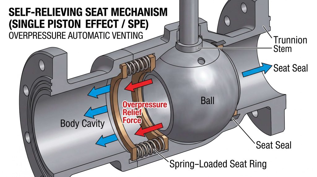
Furthermore, thermal expansion of liquid trapped inside the closed body cavity of a dual-seated ball valve can create severe hazards. In floating ball valves, cavity overpressure is naturally self-relieving, as the pressure pushes the ball slightly off the upstream seat to vent into the line. Trunnion-mounted valves, however, require specialized seat engineering, such as Single Piston Effect (SPE) self-relieving seats, to automatically vent excess cavity pressure back into the pipeline, preventing catastrophic valve body rupture.
Critical Selection Factors: Trunnion vs. Floating

When to Specify Floating Designs
For B2B procurement, floating ball valves represent an exceptionally cost-effective option for low-pressure (ASME Class 150/300) and small-diameter lines (DN15 to DN150). They are ideal for clean, non-abrasive services where operating cycles are moderate and budget constraints are tight. Because they feature fewer internal components and do not require heavy support bearings, floating designs offer a compact, lightweight isolation solution that lowers initial capital expenditure (CAPEX) without sacrificing sealing performance under standard operating envelopes.
When to Specify Trunnion-Mounted Designs
Trunnion-mounted ball valves must be specified for high-pressure pipelines (Class 600 to Class 2500), large line sizes (DN200 and above), and safety-critical process networks. They are essential for applications requiring verified Double Block and Bleed (DBB) capabilities, such as oil and gas transmission systems and aggressive slurry services in chemical plants. By transferring mechanical loads directly to heavy-duty bearings, trunnion valves maintain lower operating torque and uniform seat wear, dramatically lowering long-term maintenance costs and operational expenditure (OPEX).
Frequently Asked Questions
When should I choose a floating ball valve over a trunnion-mounted ball valve?
Choose a floating ball valve for smaller pipeline diameters (DN150/6 inches and below), lower pressure classes (Class 150/300), and clean, non-abrasive services where initial cost-effectiveness is a primary project requirement. Floating configurations are highly economical and reliable under standard operating conditions, provided the line pressure is sufficient to compress the downstream seat and the operating cycles are moderate.
What causes a floating ball valve to lock up or experience high operating torque?
High operating torque or locking in a floating ball valve is typically caused by high differential pressure, which presses the ball tightly against the downstream polymer seat. This high mechanical force increases breakout friction, sometimes exceeding the torque limit of standard actuators. This issue can be worsened by seat cold flow deformation, particulate buildup in the cavity, or elevated process temperatures that degrade polymer lubrication.
Can a trunnion-mounted ball valve seal bi-directionally?
Yes, a trunnion-mounted ball valve is designed to seal bi-directionally because it utilizes independent, spring-loaded seat assemblies on both the upstream and downstream sides of the fixed ball. Upstream pressure acts on the back of the seat ring’s piston area, pushing it tightly against the ball to form a positive seal. This design ensures highly reliable isolation from either flow direction, even in low-pressure or deep vacuum applications.
Why is cavity pressure relief critical in liquid-handling trunnion valves?
Cavity pressure relief is critical in trunnion ball valves because liquid trapped in the closed body cavity can expand thermally when exposed to solar heating or nearby process steam lines, creating extremely high pressure. Since a trunnion ball is fixed and cannot shift to vent this pressure, the trapped liquid can quickly build up to levels that exceed the valve body’s yield strength. To prevent catastrophic failure, trunnion valves must feature self-relieving seats (SPE or DPE configurations) to automatically vent excess cavity pressure back into the pipeline.
Conclusion and Engineering Summary
Selecting the proper valve configuration is not simply a matter of comparing upfront costs, but an engineering decision based on operating pressure, pipeline diameter, torque limits, and fluid characteristics. Floating ball valves remain a highly economical and reliable solution for smaller, lower-pressure pipelines. However, for high-pressure systems, larger line sizes, and critical isolation applications, trunnion-mounted ball valves are typically required to ensure uniform seat wear, lower operating torque, and true Double Block and Bleed capabilities.
With over 15 years of precision engineering experience, Ruito Flow provides high-reliability, ISO 9001:2015-certified valve solutions with CE, WRAS, and DNV compliance. Our specialized engineering team, averaging 12 years of industry experience, designs and manufactures a comprehensive portfolio of over 120 unique valve models with a field-proven defect rate of under 0.5% across production batches. To optimize your upcoming fluid processing project, contact the engineering specialists at Ruito Flow today to receive a comprehensive technical consultation and a tailored quotation for your specific application.