
Selecting a high-quality ball valve wog is critical for ensuring that piping systems handling water, oil, or gas can operate within safe pressure limits under ambient temperature conditions. In high-pressure municipal and industrial networks, unexpected pressure spikes or rapid seal degradation frequently compromise pipeline integrity, leading to costly unscheduled shutdowns. To address these operational challenges, engineers specify precision-engineered ball valves configured with appropriate body and seat ratings. This guide provides an analytical breakdown of these rating systems to assist procurement teams and plant engineers in making informed technical selections.
What Does a Ball Valve WOG Rating Mean?
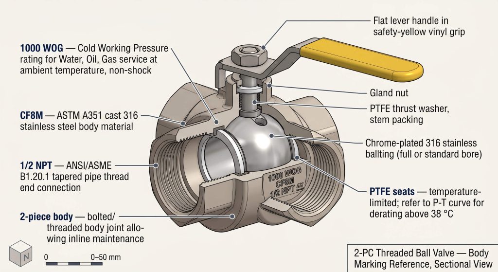
A WOG rating indicates the maximum pressure a valve can withstand when handling water, oil, or gas at ambient temperatures. This standard system allows piping designers to quickly evaluate structural suitability for utility lines and general process applications. Understanding the mechanical meaning behind these body stamps prevents catastrophic over-pressurization failures in downstream equipment.
Historical Evolution of the WOG Designation
The WOG designation historically originated as a simplified rating standard before modern, highly detailed ANSI and DIN standards were widely adopted. In early industrial piping, operators required a straightforward, unified classification to identify which valves were constructed to handle basic utility fluids without demanding complex engineering calculations. This traditional approach streamlined component inventory management across various field installations.
Over time, this system was standardized to represent non-shock working pressures at normal ambient temperatures. While contemporary projects utilize international regulatory codes, this marking remains a reliable and practical indicator for small-bore threaded valves. Standardizing this designation facilitated smoother cross-border procurement throughout the global fluid control market.
Media Categories and Ambient Benchmarks
The acronym elements define the specific fluid media—water, oil, and gas—that are chemically and physically compatible with the valve body material. These broad fluid groups represent standard industrial process media that do not introduce highly corrosive or chemically unstable reactions under ambient conditions. This compatibility ensures that the valve body maintains its structural integrity without suffering accelerated corrosion.
Ambient conditions are defined as a standard thermal range between -20°F and 100°F (-29°C and 38°C). Any operations conducted outside this specific envelope require a careful reassessment of the pressure boundaries. When the system operates at higher temperatures, the allowable pressure drops significantly below the marked rating.
Non-Shock Pressure Limitations
A WOG pressure rating represents the maximum allowable pressure under non-shock operating conditions only. This assumes that the fluid moves through the pipeline at a stable, controlled velocity without sudden pressure spikes. Under these stable conditions, the pressure remains within safe, predictable limits.
Sudden valve closure or pump startup can generate severe hydraulic shock waves, commonly referred to as water hammer. These transient surges can easily exceed the nominal rating, causing structural damage if the system is not adequately protected. Consequently, safety factors are typically integrated into piping system designs to absorb these shocks.
The Core Differences Between CWP, WSP, and WOG
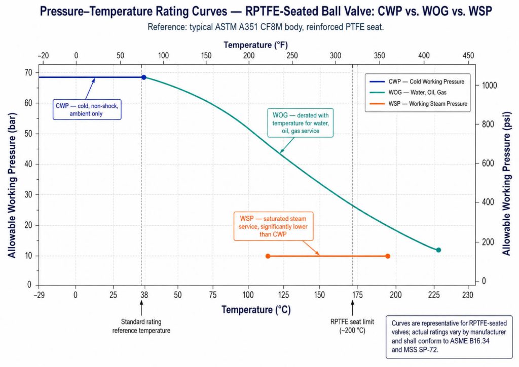
The critical difference between CWP, WSP, and WOG lies in their temperature parameters and media states. While CWP and WOG ratings reflect performance under cold, ambient conditions, WSP applies specifically to elevated steam temperatures. Failure to distinguish between these designations can lead to rapid polymer degradation and catastrophic seal blowouts.
Cold Working Pressure Temperature Envelopes
Cold Working Pressure represents the baseline pressure capacity of a valve within a standard ambient range. This metric is virtually identical to the traditional WOG rating and assumes the process fluid remains within ambient limits. It provides a foundational benchmark for engineers evaluating valve bodies under normal plant operating environments.
As operating temperatures rise above 100°F (38°C), the molecular structure of polymer seals begins to soften. This physical transition reduces the maximum pressure the assembly can safely contain, requiring a downward adjustment of the operational limit. Neglecting this reduction factors can lead to localized deformation and structural bypass at high pressures.
Saturated Steam and Thermal Degradation
Working Steam Pressure defines the maximum pressure at which a valve can operate in saturated steam systems. Saturated steam carries high thermal energy that rapidly accelerates the mechanical wear and deformation of standard elastomeric seals. Standard elastomer compounds fail under these intense thermal levels, causing total sealing loss.
Because of this severe environment, a valve’s steam rating is always a small fraction of its cold rating. For instance, a valve rated for high-pressure ambient service may be restricted to low-pressure limits when exposed to steam. Proper alignment with the steam rating ensures the polymer seats do not vaporize or lose structural elasticity.
Structural Safety and Blowout Prevention
Preventing structural failures in high-temperature lines requires specifying valves with integrated blowout-proof stems and high-grade seals. Operating a standard valve near its maximum ambient pressure in a steam system risks total seal failure. This risk is mitigated by integrating structural safety features that mechanical engineers design into standard industrial valves.
Engineers must select valves designed with robust body-to-cap connections and pressure-retaining components to prevent hazardous media escape. Proper rating alignment ensures that thermal expansion does not compromise the structural seals of the valve. These design choices ensure safe operations even under challenging thermodynamic load cycles.
Technical Specifications and Class Comparisons
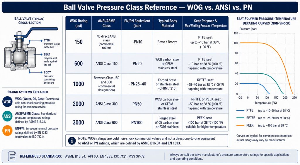
Selecting the correct pressure rating requires comparing standard WOG classes against standardized international codes. This process ensures that threaded and flanged valves align with the pressure boundaries of the connected piping. Engineers must ensure compatibility across all joints to prevent localized weak points.
Standard designations include 150, 400, 600, and 1000 ratings, each corresponding to specific industrial demands. These classes map to metric nominal pressure ratings and require distinct seat material configurations to maintain sealing. Each configuration is subject to the unique mechanical properties of the utilized alloy and seat.
| WOG Rating Class | CWP Rating at 100°F (38°C) | PN Equivalent | Nominal Sizing Range | Typical Seat Material | Standard Leakage Class |
|---|---|---|---|---|---|
| 150 WOG | 150 PSI (10.3 bar) | PN10 / PN16 | DN15 to DN300 (1/2″ to 12″) | Virgin PTFE / Elastomeric | EN 12266-1 Rate A |
| 400 WOG | 400 PSI (27.6 bar) | PN25 | DN15 to DN100 (1/2″ to 4″) | Reinforced PTFE (RPTFE) | API 598 |
| 600 WOG | 600 PSI (41.4 bar) | PN40 | DN15 to DN80 (1/2″ to 3″) | Reinforced PTFE (RPTFE) | API 598 / EN 12266-1 |
| 1000 WOG | 1000 PSI (68.9 bar) | PN64 / PN100 | DN8 to DN50 (1/4″ to 2″) | Carbon-Filled RPTFE / PEEK | API 598 / EN 12266-1 |
Pressure Class Mapping and Standards
Pressure class mapping allows engineers to cross-reference traditional markings with modern standards like ASME and DIN. This ensures that valves integrated into globally sourced piping systems maintain uniform structural safety factors. Designers can verify that pressure limits match the pipe schedule and flange specifications used across the plant.
For example, a nominal 600 rating is comparable to a PN40 class under European standards, facilitating international procurement. Proper class mapping prevents mismatched pressure boundaries that could lead to localized stress concentration. This technical alignment is crucial for heavy industrial infrastructure and high-integrity piping systems.
Seat Material and Pressure Boundary Limits
When selecting a specific ball valve wog, understanding how seat materials deform under combined pressure and thermal loads is essential. The sealing capability of polymers like virgin PTFE, reinforced PTFE (RPTFE), and PEEK decreases significantly as temperatures rise. Choosing the wrong compound can lead to rapid material extrusion and total valve bypass under ambient pressure conditions.
If the operating temperature exceeds standard limits, the seat may experience cold flow, causing structural bypass. Therefore, selecting the seat polymer is just as critical as selecting the metal alloy for the valve body. Engineers must carefully analyze the temperature-pressure curves to ensure the chosen polymer remains stable throughout the cycle.
Applications of WOG Valves Across Process Industries
Different industrial applications impose distinct physical and environmental stresses on flow control components. Matching the pressure rating of the valve to the specific requirements of each process network prevents premature wear. This step is critical in ensuring safe, uninterrupted plant operations under variable load conditions.
Hydrocarbon Processing and Petrochemical Lines
In the oil and gas industry, valves must withstand exposure to hydrocarbon fluids and volatile organic compounds. Standard ratings like 1000 WOG are commonly specified for auxiliary systems, sampling loops, and utility lines. These process paths require highly reliable body sealing to prevent external emissions.
These applications require highly reliable body sealing to prevent external emissions and maintain pressure during thermal fluctuations. Specifying the correct internal seat material prevents premature chemical degradation from sour gas and petroleum distillates. This careful selection process ensures that hydrocarbons are safely contained without risk of environmental leakage.
Industrial Water Treatment and Municipal Utilities
Piping networks within municipal water and wastewater treatment facilities operate primarily under low-to-medium pressure conditions. For these installations, 400 WOG and 600 WOG valves provide a robust, cost-effective isolation solution. They offer reliable long-term performance under continuous flow conditions without significant pressure loss.
The stainless steel or bronze constructions offer excellent resistance to municipal chemicals and water-induced oxidation. Selecting these ratings ensures long service life and minimizes maintenance interventions in municipal water lines. This structural durability makes these valves a preferred choice for water treatment facilities.
Low-Pressure Gas Distribution Systems
Transporting natural gas or propane requires valves that carry specialized safety certifications beyond standard markings. While standard water or oil systems utilize generic ratings, gas distribution networks require compliance with strict standards. This regulatory oversight ensures that materials can withstand combustible gaseous media safely.
These standards verify that the valve body and internal seals can contain volatile, low-density gases without risking leakage. Always verify that gas valves are marked with certifications like CGA-3.16 or BRS125G for safety. Compliance with these protocols is non-negotiable for industrial and municipal gas distribution networks.
Diagnostics, Maintenance, and Troubleshooting Protocols
Systematic diagnostics and scheduled maintenance are essential for extending the service life of pressure-rated valves. Regular inspections allow plant operators to detect early signs of wear before they escalate into costly failures. Following established diagnostic protocols ensures consistent sealing performance and prevents unexpected downtime.
- Downstream Leakage Detection: Inspect the seal contact surfaces for scratches or chemical erosion if fluid bypass occurs when the valve is fully closed.
- Stem Packing Tightness: If external weeping is observed around the stem, tighten the packing gland nut by a quarter-turn to compress the packing rings.
- Operational Torque Analysis: Monitor the torque required to cycle the valve; a sudden increase indicates potential seat deformation or particle entrapment.
- Thermal Cycle Integrity: Check the body joint bolts for relaxation after high-temperature thermal cycles and re-torque them to the manufacturer’s specification.
- Debris and Sediment Clearing: Flush the valve chamber regularly to prevent suspended solids from scoring the ball and damaging the soft polymer seats.
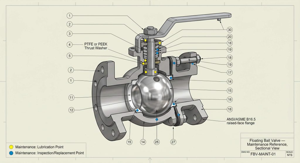
Soft Seat Wear and Leakage Prevention
Soft seat wear represents the primary cause of internal leakage in utility and process isolation valves. When abrasive particulates or thermal cycling degrade the sealing face, media can bypass the ball even in the closed position. Operators must identify these leaks early to prevent downstream contamination or fluid loss.
Regular inspection of the seat interfaces is crucial for maintaining tight shut-off integrity across pressure lines. Replacing worn polymer components during scheduled shutdowns prevents minor leaks from developing into severe high-pressure washouts. This preventive maintenance approach secures the operational reliability of the entire fluid loop.
Stem Packing Adjustments and Torque Maintenance
Stem packing relaxation can result in fugitive emissions or external fluid leakage around the actuator interface. This issue is typically addressed by adjusting the packing gland to restore the required compressive force on the seals. Regular torque checks prevent minor stem packing weepage from escalating into safety hazards.
However, over-tightening must be avoided as it dramatically increases the operating torque required to cycle the valve. Maintaining a balanced adjustment ensures seal integrity while protecting automated actuators from excessive wear. This balance is key to prolonging both packing life and actuator mechanical components.
Particle Accumulation and Flushing Techniques
Particle accumulation in the valve cavity can lead to severe scoring of the polished ball and seat surfaces. Suspended solids and rust scales tend to settle in the dead space, hindering smooth mechanical rotation. Over time, this build-up increases wear and leads to localized seal degradation.
Implementing a regular flushing protocol or installing upstream strainers helps mitigate this risk in high-solids applications. Keeping the internal chamber clean ensures consistent sealing performance and prolongs the lifetime of the soft components. These flushing steps are highly recommended for municipal wastewater and mining slurry lines.
Quality Control Standards in Valve Manufacturing
Ensuring the reliability of pressure-rated valves requires strict adherence to international quality standards during fabrication. Implementing rigorous ISO 9001-certified manufacturing processes guarantees that every valve shell is physically robust and free of structural defects. This systematic approach ensures consistent performance in demanding high-pressure applications.
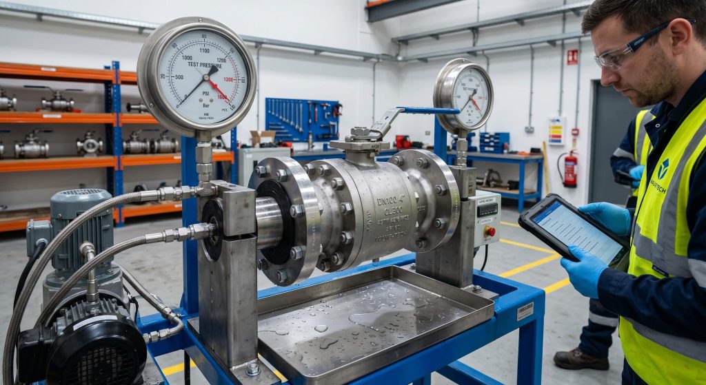
Hydrostatic Shell and Seat Integrity Testing
Hydrostatic testing is the industry standard for verifying the structural integrity of cast or forged valve bodies. During this test, the valve is subjected to pressures exceeding its nominal rating to check for casting porosity or leakage. This process verifies that the pressure-retaining boundary meets or exceeds safety factors.
These protocols, compliant with API 598, ensure that each unit can safely handle operational pressure surges without failure. Certified testing reports provide engineers with documented proof of the valve’s mechanical strength. Having these records is vital for compliance audits and project risk management.
Material Traceability and MTR Verification
Material traceability ensures that all pressure-retaining components are manufactured from verified chemical alloys. Mill Test Reports (MTRs) provide a complete chemical and physical analysis of the steel, bronze, or iron used in production. This level of oversight guarantees that the structural metal meets physical performance thresholds.
This documentation is essential for verifying compliance with international material standards like ASTM and EN. Maintaining strict traceability prevents the accidental introduction of low-grade or non-compliant metals into critical systems. Procurement teams rely on these verified certificates to ensure project reliability.
Non-Destructive Testing and Quality Audits
Non-destructive testing (NDT) techniques like radiography and ultrasonic inspection detect hidden internal flaws in high-pressure valves. These advanced methods examine the internal casting structure without damaging the physical component. This ensures that any internal voids are caught before the valve enters service.
By integrating NDT into standard quality audits, manufacturers identify subsurface defects before final machining and assembly. This rigorous quality control process guarantees that only structurally sound valves are delivered to the job site. This proactive quality assurance step protects downstream operations from unexpected failure.
Frequently Asked Questions (FAQs)
Can a standard WOG-rated ball valve be safely used in steam service?
No, standard WOG-rated valves are not designed for high-temperature steam applications without a specific steam rating. Steam service introduces severe thermal stresses and accelerated polymer seat degradation that ambient-rated valves cannot withstand. Operating a valve at its standard cold working pressure in a steam line can result in rapid seal destruction and hazardous leakage. For steam loops, operators must select valves designed with high-temperature carbon or metal seats.
What is the relationship between a valve’s WOG rating and its CWP rating?
The WOG rating and CWP rating are technically identical and represent the maximum pressure capacity at ambient temperatures. Both classifications define the non-shock pressure limit of the valve body and seats within a temperature range of -20°F to 100°F (-29°C to 38°C). When specifying a valve, a 600 WOG rating is functionally equivalent to a 600 CWP rating. As temperatures rise above this ambient window, the allowable working pressure drops according to the seat material curves.
Why do gas lines require regulatory markings in addition to a standard WOG rating?
Standard WOG markings only cover non-combustible gases and do not certify a valve for flammable or combustible utility gas lines. Combustible gases demand more rigorous safety standards to prevent volatile emissions and explosive hazards. Valves used in natural gas or propane systems must be certified under standards such as BRS125G or CAN/CGA-3.16. These certifications ensure that the valve materials and design have been tested specifically for safe gas containment.
How does seat material selection affect the maximum pressure rating of a WOG valve?
Seat material selection directly dictates the ultimate pressure and temperature limits of any WOG-rated valve assembly. While the metal valve body can withstand high pressures, soft polymer seats like PTFE are susceptible to mechanical deformation under stress. Reinforcing the seat with fiberglass, carbon, or utilizing high-density materials like PEEK increases the allowable working pressure. For high-pressure or high-temperature applications, selecting the appropriate seat material prevents premature seal failure and bypass.
Conclusion
Designing safe, efficient, and reliable piping networks requires a precise understanding of valve pressure ratings and environmental limits. Misspecifying these parameters can lead to premature seal failure, fugitive emissions, and costly process downtime. In conclusion, specifying the appropriate ball valve wog for your piping network requires a balanced evaluation of ambient pressures, media compatibility, and thermal boundaries. By carefully matching these factors with standardized pressure classes, plant operators can ensure long-term mechanical integrity.
At RUITO, our engineering team provides comprehensive support throughout the selection process, from material verification to pressure-temperature curve analysis. We assist design engineers in matching exact flow requirements with field-proven, standards-compliant valves that prevent operational failures. Our commitment to quality is backed by comprehensive hydrostatic testing and documented material traceability for every unit. To discuss your project specifications or request a detailed technical quote, please contact our technical support team today.