
To fix leaking ball valve assemblies in high-pressure industrial environments, engineers must systematically diagnose whether the leakage pathway is internal or external, isolate the line under zero-energy conditions, and either execute precise packing gland adjustments or replace compromised polymer seat and stem seals. In heavy industrial processing, fluid control systems face immense thermal, chemical, and mechanical stress. A sudden failure of inline isolation components can disrupt an entire production line, leading to pressure loss, product contamination, and increased safety hazards. Choosing the right industrial ball valves is critical to maintaining process safety and optimizing long-term operation.
Imagine a routine walkdown in an active chemical processing plant where a faint, persistent hiss betrays a critical pressure drop. A key isolation valve is bypassing, compromising downstream process metrics, causing costly media waste, and generating immediate safety risks for the field crew. In modern process environments, reliable isolation depends entirely on high-performance mechanical barriers. Resilient polymer seats (typically manufactured from PTFE, Devlon, or PEEK) rely on continuous mechanical pre-load and fluid pressure to conform to the ball’s spherical surface. Recognizing the indicators of degradation early allows engineers to execute targeted reconditioning rather than forcing complete system shutdowns.
Common Industrial Ball Valve Leak Scenarios
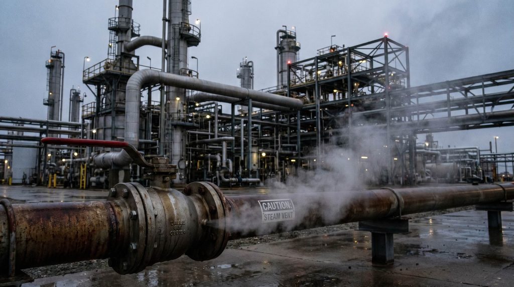
Industrial leakage represents one of the most persistent operational drains in chemical processing, power utilities, and refining facilities. When isolation valves fail to seal completely, the consequences cascade throughout the piping network. High-pressure steam or volatile organic compounds (VOCs) escaping to the atmosphere not only represent a waste of thermal energy or chemical yield but also violate stringent clean air standards.
Engineers generally classify leakage pathways into two distinct categories:
- Internal Bypass Leakage: This occurs when fluid migrates across the seating interface inside the valve body, flowing downstream even when the valve is fully closed. This is often caused by micro-abrasion of the seats, chemical degradation, or a distorted ball sphere.
- External Sealing Failure: This occurs when process fluid escapes past the stem packing or the body-to-bonnet gasket into the ambient environment. This directly exposes staff to hazardous materials and represents a major source of fugitive emissions.
The financial impact of delayed maintenance is severe, resulting in high-value product loss, fugitive emissions penalties, accelerated equipment damage, and immediate hazards to plant personnel.
Ball Valve Anatomy and Leak Failure Modes
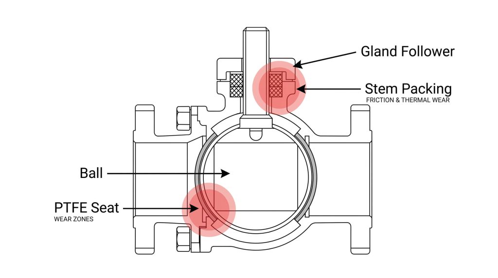
To effectively address leakage issues, it is essential to analyze the internal geometry of a standard floating or trunnion-mounted ball valve. The primary sealing boundary consists of the highly polished metal ball, two resilient or metallic seats, the valve stem, and the compressible stem packing rings housed within the stuffing box.
When the valve is cycled, the stem rotates the ball within the seats. Resilient polymer seats (typically manufactured from PTFE, Devlon, or PEEK) rely on continuous mechanical pre-load and fluid pressure to conform to the ball’s spherical surface. Sealing failures typically stem from three distinct mechanical and chemical phenomena:
- Cold Flow (Plastic Deformation): Resilient polymers under constant mechanical compressive stress tend to creep or deform permanently over time. This reduces the pre-load tension, causing low-pressure leaks.
- Chemical Corrosion and Swelling: In processes involving chemical processing applications, aggressive organic solvents or acids can chemically degrade or swell the seat materials, increasing operating torque and leading to rapid tearing of the polymer during rotation.
- Thermal Cycling Degradation: Repeated rapid shifts in operating temperature cause mismatched expansion and contraction rates between the metal valve body and the polymer seats, creating micro-gaps that invite fluid bypass.
Step-by-Step Guide to Fix Leaking Ball Valve Stem Packing
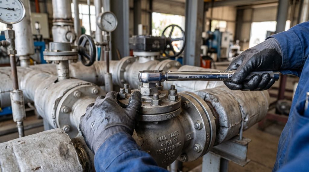
Addressing an external stem leak represents one of the most common maintenance procedures in industrial piping plants. To successfully fix leaking ball valve assemblies, technicians should first apply minor manual adjustments to the packing gland nut before committing to a full packing replacement.
If the leakage is minor and the gland follower still has travel capacity, a controlled adjustment may restore the seal:
- Clean Stem Threads: Clear any surface scale, rust, or debris from the stem threads to ensure accurate torque transmission.
- Apply the 1/6th Turn Rule: Using a calibrated torque wrench, tighten the gland nut incrementally in 1/6th-turn steps (equivalent to one flat of the hex nut). This prevents over-compression and ensures uniform packing load.
- Verify Operation: Verify that the stem rotates smoothly. Over-tightening can bind the stem, accelerating wear on the packing and exceeding actuator torque limits.
If the gland nut has reached its maximum travel and the leak persists, the packing rings must be replaced under strict zero-energy conditions:
- Isolate and Depressurize: Apply full Lockout/Tagout (LOTO) protocols. Depressurize the line entirely and cycle the valve once to discharge any fluid trapped in the body cavity.
- Remove Actuator and Hardware: Disassemble the handle, travel stops, and actuator mounting bracket to expose the gland follower.
- Extract Old Packing: Using a specialized copper or brass packing extractor tool, remove the degraded packing rings from the stuffing box. Avoid using steel tools that could scratch the polished stem or stuffing box walls.
- Inspect Stem Integrity: Check the stem for corrosion, pitting, or deep scores. If the stem has wear grooves deeper than 0.15 mm, it must be replaced to prevent rapid degradation of the new packing.
- Install New Packing Rings: Insert new pre-formed PTFE or graphite packing rings, staggering the joints by 90 to 120 degrees to eliminate a straight leak path.
- Recompress and Adjust: Reinstall the gland follower and torque the gland nut to the manufacturer’s specification. Reassemble the actuator and verify smooth operation.
Diagnostic Protocols and Non-Destructive Leak Testing

When plant operators attempt to fix leaking ball valve units, they often overlook the diagnostic phase, jumping directly to mechanical intervention. Applying systematic, non-destructive testing (NDT) protocols ensures that maintenance activities are targeted and effective:
- Ultrasonic Acoustic Emission Testing: As pressurized fluids escape through micro-gaps in a closed valve seat, they generate high-frequency turbulent noise. Technicians can use specialized ultrasonic probes to detect these acoustic signatures, pinpointing the leak location without stripping insulation or dismantling flanges.
- Differential Pressure Decay Testing: By isolating the valve and pressurizing the upstream side with dry nitrogen, technicians can monitor pressure changes over a set period. A measurable drop on the upstream gauge combined with a pressure rise downstream confirms internal seat bypass.
- Helium Mass Spectrometry: For critical fugitive emissions compliance (such as ISO 15848-1 standards), helium is introduced into the valve body while a mass spectrometer sniffer probe tests the stem packing area. This represents one of the most sensitive methods for detecting micro-leaks.
High-Performance Seat and Seal Material Selection
Selecting the appropriate seat material is the most critical factor in preventing premature valve leaks. The table below outlines the technical envelopes and performance limits of common polymer and metallic seat designs used in modern process industries.
| Seat Material | Temperature Limits | Maximum Working Pressure | Primary Failure Mode | Typical Standard Compliance | Application Suitability |
|---|---|---|---|---|---|
| Virgin PTFE | -100 °C to 200 °C | 150 PSI (Class 150) | Cold flow, mechanical creep under continuous high load | FDA, USP Class VI | Clean utilities, low-pressure water, and mild acids |
| Reinforced PTFE (RTFE) | -100 °C to 220 °C | 300 PSI (Class 300) | Micro-cracking during rapid thermal cycles | ASME B16.34 | Process chemical lines, low-pressure steam, and hydrocarbons |
| Devlon V-API | -100 °C to 150 °C | 6,000 PSI (Class 2500) | Swelling and binding due to high moisture absorption | API 6D / ISO 5208 | High-pressure natural gas, oil pipelines, and subsea valves |
| PEEK | -100 °C to 260 °C | 10,000 PSI (Class 4500) | Brittle fracture under intense physical shock | API 6D, ISO 10497 | High-temperature process lines, geothermal, and high-pressure steam |
| Metal-to-Metal (Tungsten Carbide) | -196 °C to 550 °C | 15,000 PSI (Class 4500+) | Fine particulate abrasion under severe cyclic slurry flow | API 6D, API 598 | Highly abrasive slurries, mining tailings, and extreme temperatures |
Using condition-based engineering logic, virgin PTFE should be limited to non-cyclic utility systems, while reinforced polymers (RTFE or PEEK) are required for demanding thermal and mechanical applications. For extreme services involving abrasive slurries, specifying a metal-seated design with specialized hard-coatings is often necessary to prevent premature seating failure.
Proactive Preventive Maintenance for Valve Longevity
Unplanned shutdowns can be minimized by transition from reactive repairs to a structured preventive maintenance strategy. For valves operating in heavy scaling environments, such as water & wastewater treatment installations, mineral precipitation can cause rapid seat degradation.
- Partial Stroke Testing (PST): Actuated valves can be programmed to cycle by 15 to 20 degrees at regular intervals. This partial movement clears mineral scaling and particulate buildup from the ball surface without disrupting process flow, reducing the risk of seat damage during full cycles.
- Automated Cycling Protocols: High-cycle applications benefit from scheduled, automated cleaning strokes to clear particulate buildup before it hardens.
The following cycling guidelines should be integrated into the plant’s maintenance management system:
| Water Hardness Metric | CaCO₃ Concentration | Recommended Cycling Frequency | Maintenance Action |
|---|---|---|---|
| Soft Water | 0 to 60 mg/L | Every 6 months | Perform one 100% full-stroke open-to-close cycle to clear light film |
| Moderately Hard | 61 to 120 mg/L | Every 3 months | Dual-stroke cycle; record actuator torque variations |
| Hard Water | 121 to 180 mg/L | Monthly | Perform 3 consecutive cycles to clear mineral deposits from seating faces |
| Very Hard / Slurry | >180 mg/L | Every 2 weeks | Continuous PST (15%); high-pressure flush of body cavity if equipped |
Reconditioning versus Full Valve Replacement Decision Matrix
When managing valve assets, plant engineers must decide whether to recondition an existing unit or replace it entirely. While minor stem leaks are easily field-adjusted, deep structural wear can compromise the valve’s pressure retention capability.
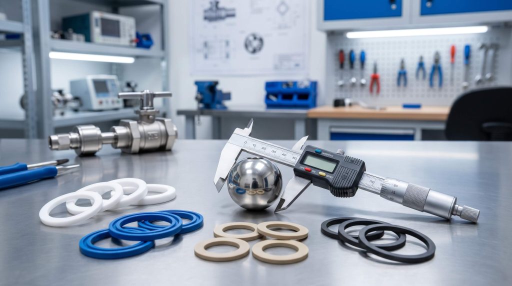
To support this evaluation, maintenance teams should assess physical components against standardized criteria:
- Body Integrity: Check wall thickness using ultrasonic thickness gauges. If erosion has reduced the wall thickness below the minimum limits specified in ASME B16.34, immediate replacement is required.
- Ball Spherical Tolerances: Measure the ball surface roughness and roundness. If surface scoring exceeds 0.05 mm, the ball will rapidly destroy replacement soft seats, requiring a new ball or full valve replacement.
- Seat Pocket Geometry: Inspect the machined seat pockets in the valve body. If corrosion has pitted the pocket walls, new seat rings will not seal correctly, leading to continuous bypass.
For critical applications, partnering with a manufacturer that utilizes a comprehensive, ISO 9001-certified manufacturing process ensures that replacement valves meet all relevant metallurgical and pressure-testing specifications, providing long-term reliability.
*
FAQ
Can a ball valve leak when it is in the fully closed position?
Yes. Internal seat bypass can occur even when the stem handle indicates the valve is completely closed. This is typically caused by debris scraping or cutting the polymer seats, chemical degradation of the elastomer, or thermal cycling that causes the seating polymer to deform (cold flow). Over time, these structural compromises allow the process medium to pass between the ball and seat, continuing downstream and compromising isolation integrity.
What is the difference between an adjustable packing gland and a live-loaded packing system?
An adjustable packing gland requires manual maintenance technicians to periodically tighten the gland nut to compress the packing rings, compensating for natural wear. A live-loaded packing system, however, utilizes Belleville spring washers stacked above the gland follower to maintain constant, uniform tension on the stem packing. This self-adjusting mechanism absorbs thermal expansion and cycle-induced wear, reducing the risk of fugitive emissions without requiring manual intervention.
How do you determine if a leaking ball valve requires stem packing adjustment or a complete replacement?
If the leakage is external and escaping from the stem, and the gland nut still has room for travel, a manual adjustment using the 1/6th turn rule can often resolve the leak. Conversely, if the leakage is internal (flowing downstream while closed) or if physical inspections reveal deep scoring on the stem or body corrosion, adjusting the gland will not solve the issue. In these scenarios, the valve must be isolated and undergo complete element replacement or a full valve rebuild.
Why does cavitation occur in ball valves, and how does it cause seat damage?
Cavitation occurs when a fluid passes through a partially open valve, creating a high-velocity localized zone where the static pressure drops below the fluid’s vapor pressure, forming vapor bubbles. As these bubbles move into areas of higher pressure downstream, they collapse violently and generate localized shockwaves with pressures reaching up to 100,000 PSI. These repetitive micro-implosions erode the metallic ball and rapidly tear or fracture adjacent polymer seats.
How does hard water accelerate internal ball valve leakage?
Hard water contains high concentrations of calcium carbonate (CaCO₃), which precipitates out of the fluid to form a rigid mineral scale on the highly polished surface of the ball. During actuation, this scale acts as an abrasive, scoring the soft polymer seats and creating small bypass pathways. Furthermore, severe scale accumulation inside the valve body cavity can physically block the ball from rotating into its fully sealed position, resulting in continuous bypass leakage.
Conclusion
Maintaining industrial flow control integrity requires a proactive approach to seat and stem sealing diagnostics. By understanding the mechanical, chemical, and thermal wear mechanisms that cause leaks, process engineers can implement precise step-by-step repair protocols and make informed recondition-versus-replace decisions. Adhering to standards such as API 598 and implementing regular cycling frequencies prevents premature failures and minimizes expensive unplanned downtime.
RuitoFlow supports industrial operators by providing complete material traceability, exceptional manufacturing transparency, and dedicated engineering support to ensure every valve complies with the highest international standards. To discuss your project specifications or to select the ideal valve configuration for your high-pressure and high-cycle applications, please consult with our technical sales engineers today.