
Selecting a high-performance cold water tank ball valve is essential for maintaining optimal water volume control and preventing structural overflows in commercial distribution networks. In large-scale industrial facilities, managing water reserves requires highly reliable level control to ensure uninterrupted process flow. Without a robust mechanical shutoff mechanism, facilities often experience rapid system pressure drops, piping degradation, or catastrophic overfill incidents. By installing an advanced industrial ball valve designed specifically for high-capacity applications, engineers can maintain stable storage parameters and minimize operational downtime.
Engineering Water Level Control and Air Gap Compliance
Maintaining exact fluid thresholds in industrial storage systems requires positive backflow prevention and structurally integrated physical boundaries.
Analyzing Potable System Risk Profiles
Piping engineers must identify potential contamination pathways within complex water distribution networks to protect potable supplies. Back-siphonage occurs when a sudden drop in upstream pressure draws stored water back into the municipal system. When integrating a cold water tank ball valve into an industrial potable water storage vessel, engineering teams must prioritize system dynamics to prevent contamination risks. These installations must comply with strict regional fluid hygiene protocols to maintain separation between process water and utility lines.
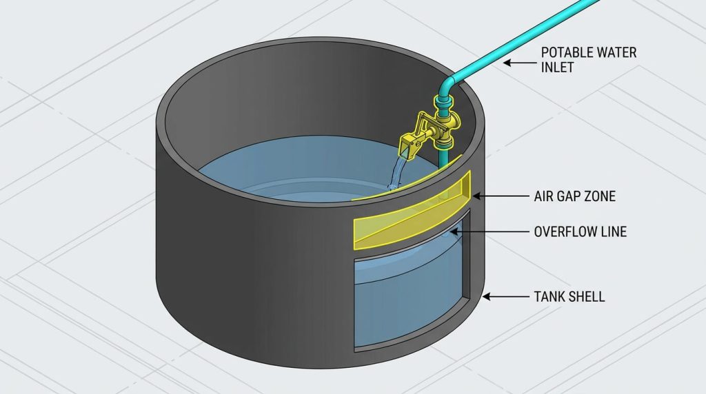
Design Parameters for Type AB Air Gaps
A Type AB air gap utilizes a non-mechanical physical barrier to prevent back-siphonage under variable pressure conditions. This setup requires an open, unobstructed spill-slot cut directly into the side of the tank below the inlet level. This design prevents the water level from ever reaching the valve outlet, even during high-inflow events or mechanical failures. Proper dimensioning of this physical gap must account for the maximum theoretical inlet pipe diameter to ensure reliable air flow.
Fluid Dynamics of Balanced Equilibrium Mechanics
Equilibrium level valves utilize a double-seated balance mechanism to mitigate the high force requirements of volatile upstream pressures.
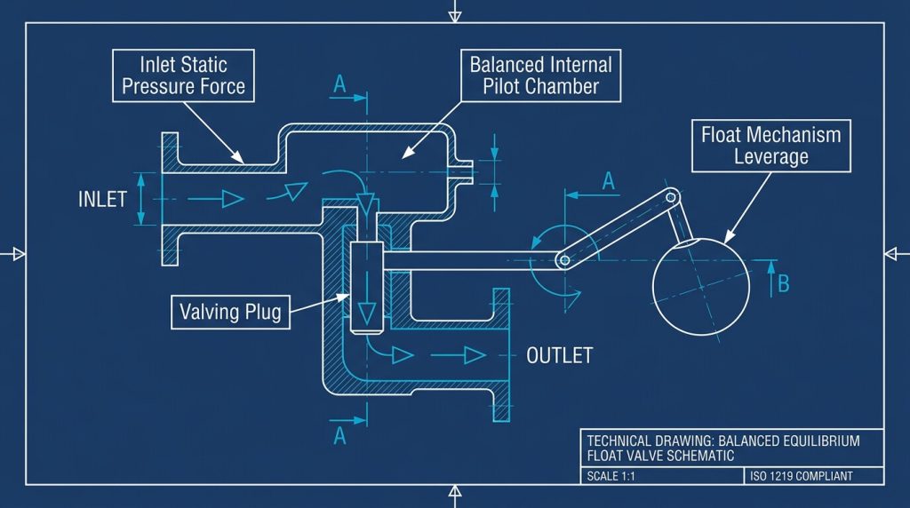
Force Balancing in Valve Chambers
Standard float systems face significant operational challenges when subjected to extreme upstream pressure fluctuations. To counter this, equilibrium designs direct incoming water pressure to both sides of the inner valving plug. This equalization neutralizes the hydraulic forces acting on the sealing faces, reducing the torque required for actuation. Consequently, a much smaller float can reliably close the valve, preserving internal sealing integrity over long service cycles.
Leverage Calculations for Heavy-Duty Floats
Calculating the mechanical advantage of the float leverage arm requires precise dynamic torque calculations. The buoyancy force generated by a submerged copper or polyurethane sphere must overcome the internal seal friction of the seat. High-pressure applications require extended leverage configurations or heavier counterweighted linkages to maintain positive shutoff. A carefully calibrated mechanical linkage reduces premature mechanical wear on the primary pivot points.
To achieve high precision in larger systems, engineers often transition from direct mechanical leverage to an integrated modulating control valve array.
Managing Transient Pressure Waves and Water Hammer
Mitigating hydraulic shock requires controlled closure rates to preserve the structural integrity of both valves and lines.
Solenoid and Pilot-Assisted Delay Mechanics
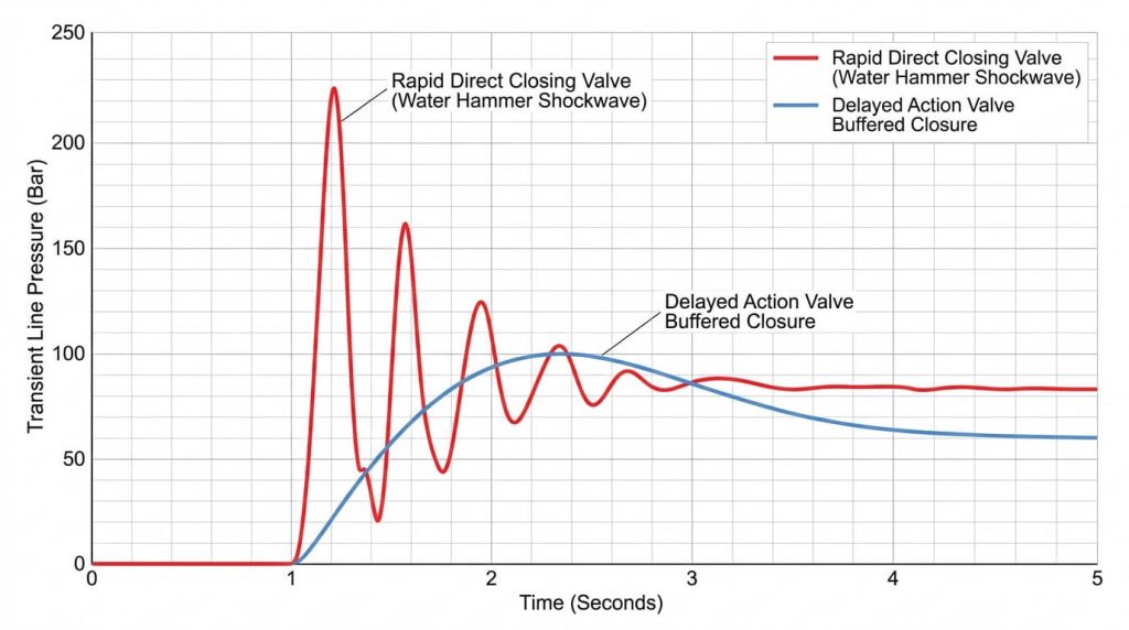
Rapid close-off configurations frequently generate severe transient pressure spikes known as water hammer. Pilot-assisted delayed action systems isolate the main seating element from direct, rapid float movements. By utilizing a small pilot valve to control a secondary chamber, the main valve can close gradually. This dampens the deceleration rate of the fluid column and protects adjacent pipe welds from structural fatigue.
Predicting Peak Transient Line Pressures
Engineers utilize transient analysis models to determine the maximum pressure waves generated during valve shutoff cycles. Uncontrolled shockwaves can exceed nominal pipe ratings, leading to catastrophic joint separation or seal rupture. Incorporating mechanical shock arrestors or choosing delayed-action float systems mitigates these spikes. Keeping the closure velocity within predetermined thresholds protects expensive downstream booster pumps and filtration systems.
Structural Variations of Level Control Systems
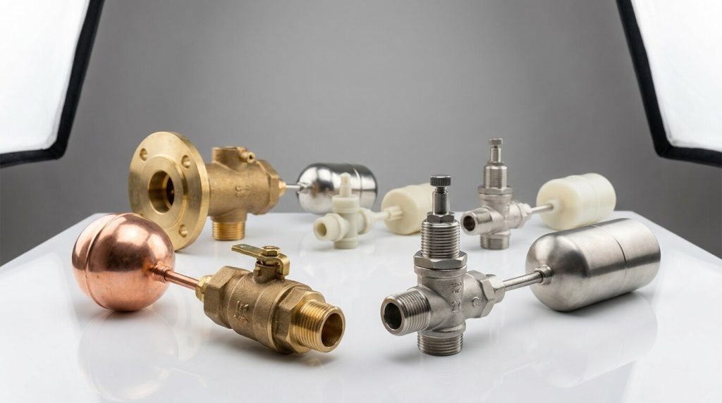
Commercial scale storage configurations utilize distinct float arm options depending on vertical headspace restrictions.
Straight Arm vs Drop Arm Configurations
Straight arm float designs are suitable for standard open-tank installations where vertical space is not restricted. However, tanks with raised chambers or tight enclosures require a drop arm configuration to position the float properly. This drop arm allows the float to sit deeper in the tank relative to the high valve body mounting location. This design helps maintain the required physical air gap while ensuring complete tank volume utilization.
Sizing a Cold Water Tank Ball Valve
Determining the physical footprint and connection size requires a careful assessment of peak process flow demands. Sizing a cold water tank ball valve requires matching calculated flow coefficients with specific system inlet dynamics. Oversized valves cause frequent short-cycling, whereas undersized valves restrict inlet flow and reduce system efficiency. Selecting the correct connection size ensures stable operation and a reliable fluid velocity profile.
Selecting Metallurgical Alloys for Long Service Life
Specifying correct metallurgy remains the primary defense against localized crevice corrosion and dezincification in wet environments.
Dezincification Resistance of Copper Alloys
Standard brass alloys frequently suffer from dezincification when exposed to municipal water with high chloride levels. This process leaches zinc from the alloy, leaving a porous, structurally weak copper frame prone to pinhole leaks. Utilizing specialized gunmetal or high-grade ASTM B62 bronze provides superior resistance to this dezincification process. This choice is particularly vital for buried pipelines or inaccessible overhead storage tank inlets.
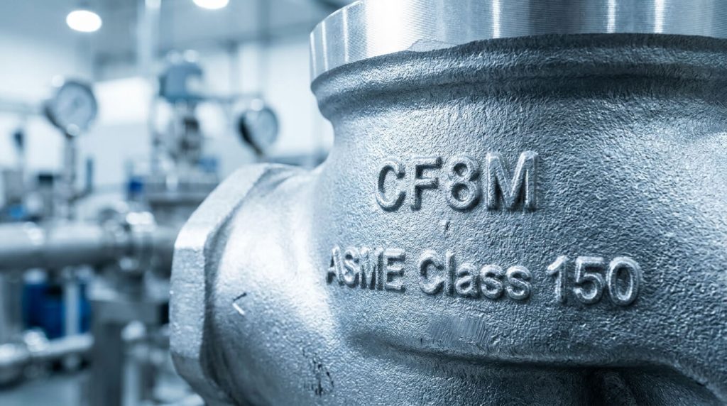
Corrosion Protection of Cast Stainless Steel
For chemical processing plants, food-grade storage, or demineralized water systems, stainless steel is the preferred option. Specifying ASTM A351 CF8M stainless steel introduces molybdenum, which provides exceptional resistance to chloride-induced pitting. Working with a dedicated provider of custom valve manufacturing ensures the casting matches these precise metallurgical requirements. High-quality casting and heat treatment protect against intergranular corrosion under high temperature and pressure.
Engineering Specifications and Piping System Sizing

Accurate valve sizing requires matching calculated flow coefficients with specific system inlet dynamics.
Utilizing Flow Coefficients for NPS Selection
Choosing the correct cold water tank ball valve involves a comprehensive analysis of inlet pressure variations and flow requirements. Sizing should be based on calculated Cv or Kv values rather than simple line-size matching. Choosing a valve based solely on existing pipe dimensions can lead to high pressure drops or excessive velocity through the port. Properly sized valves maintain the fluid velocity below the wear-inducing threshold of five feet per second.
Pressure Class Standard Compliance
Valves selected for high-rise commercial structures or industrial facilities must conform to established pressure ratings. Systems designed with ASME Class 150 or Class 300 flanges provide the necessary structural strength to withstand upstream pressure surges. Compliance with ASME B16.34 wall thickness and ANSI testing standards is crucial to prevent mechanical failures. Engineering documentation must specify these standards to ensure the valves can withstand peak system pressures.
Integrating Level Control in Municipal Storage Systems
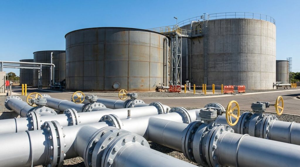
Municipal water distribution infrastructure relies on synchronized level control arrays to maintain continuous regional supply pressure.
Booster Set Integration Parameters
Industrial storage tanks connected to high-capacity booster pumps require carefully synchronized level control valves. Sudden valve closures can cause upstream booster pumps to deadhead, leading to rapid motor overheat and seal failure. Integrating mechanical delayed-action valves helps prevent pump short-cycling by allowing a wide differential between opening and closing levels. This setup ensures consistent pump run times, which extends the service life of high-horsepower motor components.
Redundant Protection Valve Arrays
Critical municipal reservoirs utilize multiple redundant valves to protect against single-point failure risks. Installing a high-performance non-return valve downstream of the booster set prevents backflow during pump shutdown cycles. Combining an equilibrium float valve with a pilot-operated backup ensures that the tank cannot overflow even during mechanical linkage failures. This multi-barrier design protects surrounding infrastructure from water damage and maintains system reliability.
Engineering Selection Matrix for Cold Water Level Control
The table below provides comparative technical guidelines for selecting level control mechanisms based on material performance and typical industrial applications.
| Design Classification | Primary Construction Materials | Applicable Manufacturing Codes | Operational Pressure Range (CWP) | Operational Temperature Limits | Ideal Application Environment |
|---|---|---|---|---|---|
| Mechanical Equilibrium (Straight Arm) | ASTM B62 Bronze / ASTM A351 CF8M | BS 1212-1 / ASME B16.34 | 0.5 to 10.0 Bar | Designed for fluid systems up to 60°C | High-capacity municipal reservoirs with balanced supply |
| Mechanical Equilibrium (Drop Arm) | ASTM B62 Bronze / ASTM A351 CF8M | BS 1212-1 / ASME B16.34 | 0.5 to 10.0 Bar | Designed for fluid systems up to 60°C | Raised valve chambers requiring air gap backflow compliance |
| Delayed Action Float (K-Type) | ASTM A351 CF8M / Gunmetal | BS 1212-1 / ISO 5208 | 1.0 to 12.0 Bar | Designed for fluid systems up to 40°C | Systems vulnerable to seat erosion and water hammer |
| Hydraulic Pilot Operated | ASTM A216 WCB / ASTM A351 CF8M | ASME B16.34 / API 598 | 1.0 to 16.0 Bar | Designed for fluid systems up to 80°C | Large-scale multi-tank industrial booster installations |
Frequently Asked Questions on Tank Valves
How does supply line pressure fluctuation affect equilibrium ball valve shutoff performance?
Equilibrium valves mitigate upstream fluctuations. The balanced pilot design of an equilibrium level valve allows upstream line pressure to act simultaneously on both sides of the valving element. This pressure equalization minimizes the physical leverage required from the float arm. Consequently, the valve maintains consistent shutoff parameters and prevents seat weeping even during sudden municipal pressure spikes.
Why are delayed action float valves preferred over standard mechanical float valves in systems with booster pumps?
Delayed action systems prevent pump short-cycling. Progressive mechanical float valves close slowly, resulting in a prolonged throttling phase that restricts flow and causes seat erosion. Delayed action systems remain fully open until the fluid reaches a predefined high level, then shut off rapidly. This wide operational differential reduces booster pump start-stop cycles, extending motor and pump life.
What are the essential maintenance intervals for an industrial cold water level control valve?
Routine mechanical inspection is recommended biannually. In municipal and commercial systems, level control valves should undergo functional testing and seal inspections every six months. Technicians must check the pivot point linkages for signs of corrosion and verify that the physical air gap remains unobstructed. Elastomeric seals and float balls should be replaced based on local water hardness and wear parameters.
Can equilibrium drop-arm valves prevent backflow in Category 5 municipal water installations?
Drop-arm valves enable backflow compliance when properly configured. While a drop-arm valve is not a mechanical backflow preventer, its physical structure allows the outlet to be mounted high above the overflow level. This configuration is critical for maintaining a Type AB air gap, which is a key requirement for Category 5 fluid networks. Correct installation ensures physical separation between the municipal inlet and the potential contaminants inside the reservoir.
Choosing Ruitoflow for Industrial Systems
Effective flow management in commercial and municipal cold water storage requires selecting the correct combination of hydraulic balance, material grade, and regulatory compliance. Rather than relying on standard commercial utility fixtures, modern water storage networks demand high-integrity components that withstand transient pressures and corrosive chemistry. Choosing the correct structural design—whether a balanced equilibrium linkage or a delayed action system—preserves downstream infrastructure and minimizes total cost of ownership.
As a leading high-performance industrial valve manufacturer, RUITO specializes in delivering robust, engineered fluid control systems designed to meet ASME, API, and ISO specifications. Our specialized technical division is available to assist engineering teams with precise material specification, custom dimensions, and fluid dynamics analysis. To optimize your next municipal or commercial liquid storage project, contact our design specialists to review your pipeline layouts and request a valve quote today.