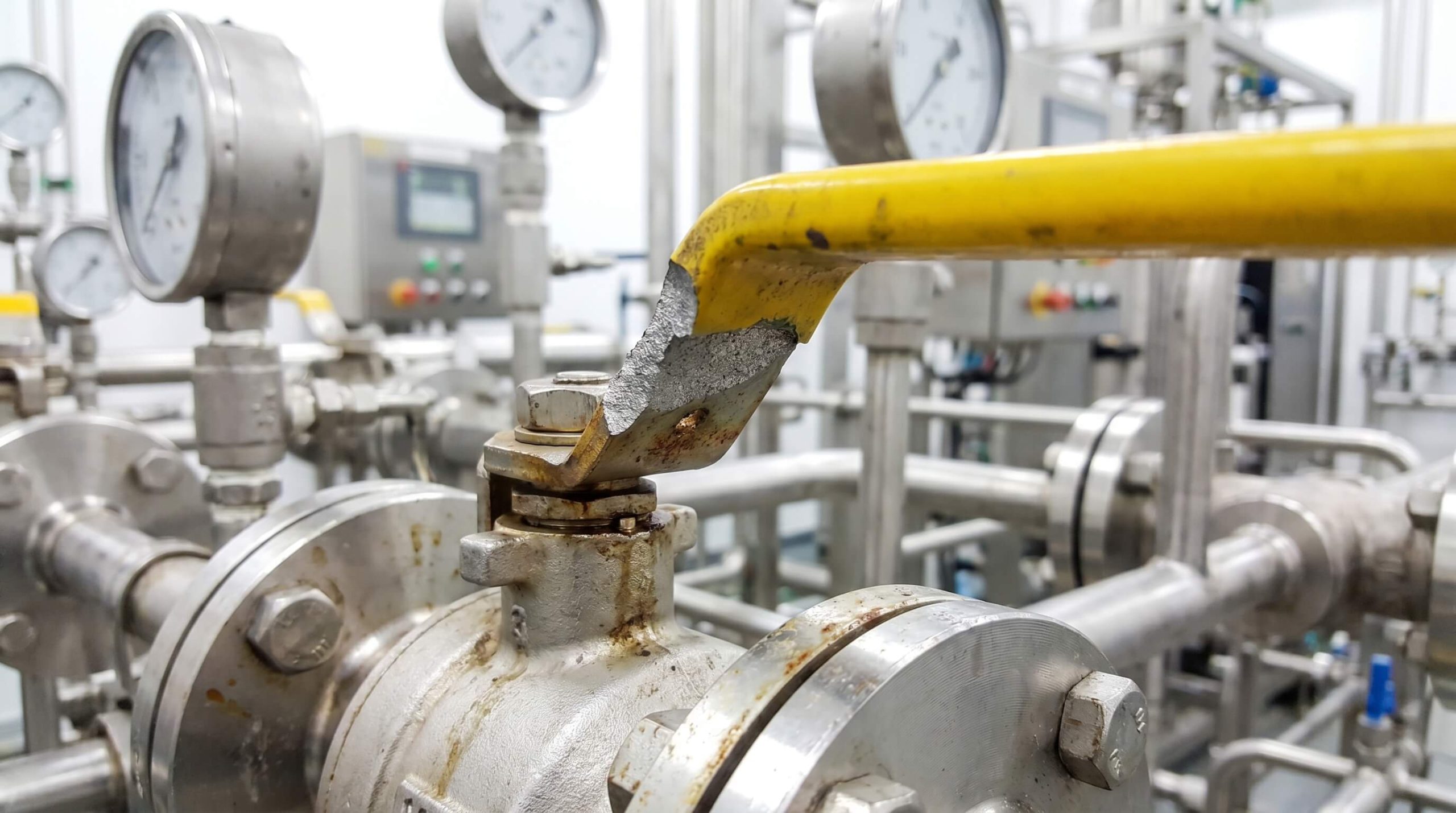
When an industrial ball valve handle broke off during operation, the primary solution is to safely isolate the pipeline, depressurize the system, and use parallel-jaw tools to rotate the stem before installing a high-durability replacement lever. In high-pressure chemical facilities and refining plants, the sudden failure of a manual override lever is rarely an isolated mechanical issue. Instead, it frequently points to deeper systemic issues, such as media crystallization, polymer seat degradation, or localized galvanic corrosion within the handle-stem interface.
For maintenance teams managing critical process pipelines, resolving a sheared lever is about restoring immediate system control while diagnosing why the torque threshold of the component was exceeded. By understanding the mechanical dynamics and material limits of industrial ball valves, facility operators can prevent costly piping repairs, protect upstream equipment, and maintain safe, continuous operations.
Why Your Ball Valve Handle Broke Off in Service

Mechanical failures of quarter-turn manual operators usually stem from high breakaway torque, galvanic corrosion, or advanced material fatigue. When a standard handle is designed, the manufacturer calibrates its length and thickness to easily overcome the standard breakaway torque of the internal ball-and-seat interface. However, when process conditions change or the valve remains stationary for extended periods, the mechanical forces required to operate the valve rise significantly.
Mechanical Over-Torquing and Scale Accumulation
When particulate matter, crystallized process media, or mineral scale accumulates within the valve cavity, the friction between the ball and seat increases. If an operator attempts to cycle the valve under these conditions, the required operating torque can easily exceed the shear strength of the handle adapter. This situation is frequently exacerbated by the unauthorized use of extension pipes or “cheater bars,” which multiply the mechanical torque beyond the valve’s designed safety limits. In these scenarios, when a ball valve handle broke off, it is usually a symptom of a seized internal ball rather than a simple defect in the lever itself.
Galvanic Corrosion and Material Thinning
Dissimilar metals in direct contact often initiate localized galvanic corrosion, significantly degrading the mechanical integrity of the handle connection. For instance, pairing a zinc-plated carbon steel lever with a stainless steel stem in a humid or coastal environment establishes an active electrochemical cell. The less noble carbon steel or zinc serves as a sacrificial anode, suffering rapid material loss and thinning. Under standard quarter-turn operation, the weakened interface fails catastrophically long before the stem itself experiences any plastic deformation.
UV Exposure and Polymer Fatigue
Many lightweight utility valves utilize reinforced nylon or low-grade die-cast zinc alloys to reduce manufacturing costs. When these materials are subjected to persistent outdoor ultraviolet radiation or cyclic thermal expansion, their molecular structure degrades. Polymer handles undergo micro-cracking and embrittlement, while zinc die-cast materials suffer from intergranular corrosion under high humidity. The resulting reduction in tensile strength ensures that even a minor increase in stem operating torque can trigger a sudden, catastrophic mechanical fracture.
Safety Procedures for Pressurized Pipelines
Implementing structured safety shutdown protocols is mandatory before attempting any manual stem manipulation or component replacement on a live process line. The moment a valve handle fails, the line must be treated as unstable, particularly if the valve is stuck in a partially open position. Technicians must immediately identify the corresponding process loop on the facility’s Piping and Instrumentation Diagrams (P&IDs).
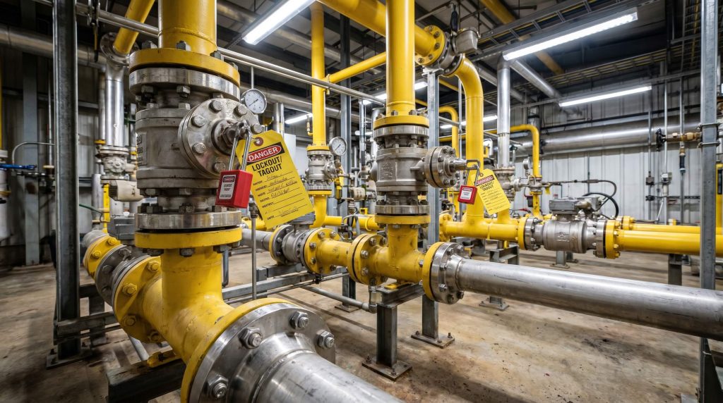
System Isolation and Lockout-Tagout Protocols
Upstream pumps must be powered down, and neighboring isolation valves must be manually closed and locked out using certified safety padlocks and warning tags. No technician should perform mechanical work on a damaged valve assembly without verifying that the energy pathways feeding the line are completely isolated. Unlike standard gate valves, which utilize multi-turn stems and slow closing times, quarter-turn valves can cycle rapidly, inducing water hammer if operated improperly under pressure.
Complete Line Depressurization
Trapped process fluid must be drained safely to minimize the risk of media blowout and catastrophic stem seal leakage during emergency manual operations. Any residual line pressure exerts axial forces against the valve stem packing, which can be disturbed if lateral forces are applied to the stem without a proper handle assembly. Maintenance crews should open downstream drain valves or vent ports to bleed off the trapped process fluid into a safe containment vessel. Inline transmitters and pressure gauges must be monitored continuously until they display a stable, zero-pressure state.
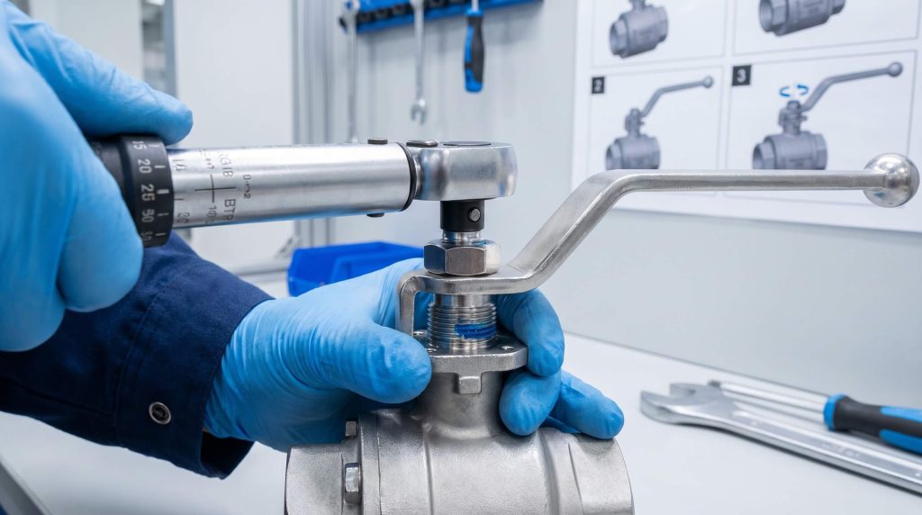
What to Do When a Ball Valve Handle Broke Off
Manipulating a bare valve stem requires the use of specialized parallel-jaw tools to prevent surface deformation and preserve the integrity of the stem seal. When a ball valve handle broke off and immediate shut-off is required to prevent process contamination or environmental release, operators often reach for standard pipe wrenches or serrated pliers. These tools can cause permanent damage to the valve stem if used incorrectly.
Avoiding Pipe Wrenches and Serrated Tools
Standard pipe wrenches and pliers feature hardened, serrated teeth that bite into metal to achieve grip. While effective on rough piping, these tools can easily gouge and score the precision-ground surfaces of a valve stem. Such surface defects destroy the smooth profile required by the valve’s packing rings, causing localized gaps that eventually lead to severe fugitive emissions. Technicians should only use flat-jaw wrenches, parallel-jaw pliers, or custom stem adapters that distribute force cleanly across the stem flats.
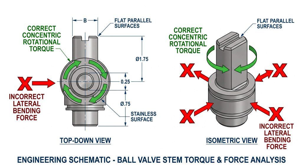
Minimizing Lateral Stem Loads
Applying force to only one side of the stem introduces a significant bending moment, compressing the packing gland on one side while opening a micro-gap on the other. This lateral load can cause immediate leakage of hazardous chemicals or gases if any residual line pressure remains. To prevent this, operators must apply pure, concentric rotational torque, ensuring the force is directed solely around the stem’s central axis to maintain seal concentricity.
Engineering Analysis of Handle Materials
Selecting the correct metallic or non-metallic handle alloy requires evaluating the service environment’s chemical aggressiveness, maximum operating temperature, and required structural torque. In industrial piping systems, handle materials must withstand high mechanical stress and resist environmental degradation over long service cycles. While carbon steel and polymer handles are common in light utility lines, heavy chemical and coastal installations demand high-performance alloys.
Handle Material Performance Comparison
The table below details the performance characteristics of various handle materials under standard industrial operating parameters.
| Material Specification | Yield Strength (MPa) | Corrosion Resistance (pH Range) | Maximum Operating Temp (°C) | Relative Cost Index | Primary Failure Mode |
|---|---|---|---|---|---|
| ASTM A240 316 Stainless | 290 – 320 | 1.0 – 14.0 (Excellent) | 600°C | High | Stress corrosion cracking (extreme conditions) |
| ASTM A240 304 Stainless | 205 – 240 | 2.0 – 12.0 (Good overall) | 450°C | Medium-High | Chloride pitting in marine environments |
| Carbon Steel (Zinc Plated) | 250 – 350 | 6.0 – 9.0 (Poor in Acid/Chloride) | 200°C (Coating limits) | Low | Atmospheric oxidation, galvanic thinning |
| Aluminum Alloy (Anodized) | 150 – 270 | 4.0 – 8.5 (Moderate) | 150°C | Medium | Thread stripping, alkaline degradation |
| Zinc Alloy (Zamak 3/5) | 200 – 250 | 5.0 – 11.5 (Poor in acid) | 120°C | Low-Medium | Intergranular corrosion, “white rust” cracking |
| Reinforced Nylon/Polymer | 50 – 90 | 1.0 – 14.0 (Chemical dependent) | 90°C | Low | UV embrittlement, thermal creep fatigue |
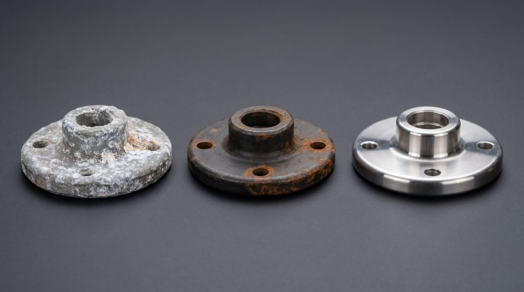
Chemical Resistance and Alloy Selection
ASTM A240 316 stainless steel contains molybdenum, which dramatically improves its resistance to localized pitting and stress corrosion cracking compared to 304 stainless steel. In contrast, cost-effective zinc-plated carbon steel relies heavily on its superficial coating. Once that layer is breached by mechanical wear or acidic washdowns, raw carbon steel oxidizes rapidly, leading to mechanical thinning and eventual handle failure under normal operating loads.
Step-by-Step Replacement Instructions
Replacing a damaged valve handle involves extracting failed fasteners, cleaning the stem flats, and torquing the new lever to the manufacturer’s exact specifications. This procedure should only be performed once the pipeline segment has been verified as completely isolated and depressurized.
Extracting Broken Fasteners
If the ball valve handle broke off because of a seized fastener, the remaining bolt segment or rusted nut must be removed without damaging the stem threads. Technicians should apply a professional-grade penetrating lubricant to the thread interface and allow it to work for 15 to 30 minutes. If the bolt head has sheared flush with the stem, a left-hand drill bit or a specialized screw extractor should be used at low speeds to cleanly pull the thread remnant out.
Cleaning and Preparing Stem Flats
After removing the fastener remnants, the stem flats must be inspected for wear and corrosion. Use a fine stainless steel wire brush and a compatible solvent cleaner to remove scale, rust, and old paint from the mounting surfaces. Check the stem flats for any signs of torsional twisting; if the flats are out of alignment, the stem itself has yielded under torque and must be replaced to prevent future slippage.
Securing and Calibrating the New Lever
Slide the new handle onto the cleaned stem flats, ensuring a snug fit with no rotational play. Apply a medium-strength anaerobic thread-locking compound to the threads of the retaining bolt or nut. Tighten the fastener using a calibrated torque wrench to the manufacturer’s recommended installation torque, and execute multiple manual cycles to verify correct alignment with the internal ball.
Preventing Future Handle Failures
Designing manual valve stations with strict torque limits and adopting pneumatic actuators minimizes physical strain on the valve components. To prevent mechanical over-stress, the lever length must be calculated so that an operator cannot exceed the valve’s Maximum Allowable Stem Torque (MAST).
Understanding Maximum Allowable Stem Torque
The MAST represents the physical limit before the stem suffers plastic deformation or catastrophic shear. It is mathematically calculated based on the minimum stem diameter and the shear yield strength of the material:
$$\text{MAST} = \frac{\pi \cdot d^3 \cdot \tau_y}{16}$$
By keeping the manual handle short enough, plants prevent operators from using excessive leverage that could damage the stem or packing. If a valve requires more torque to operate than a standard lever can provide, the system requires diagnostic attention rather than a longer handle.
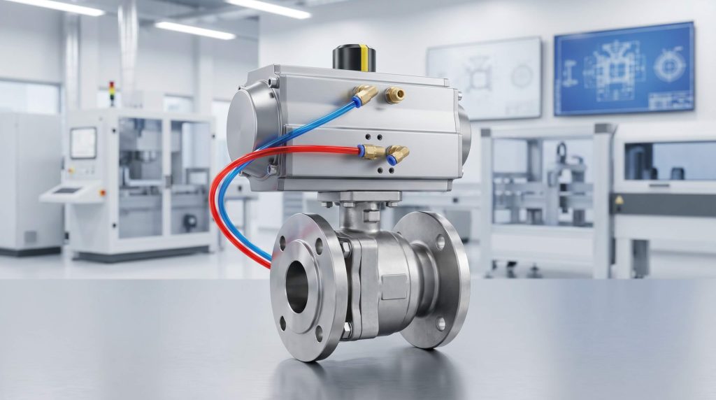
Transitioning to Automated Actuation
For high-cycle or high-torque applications, replacing manual levers with pneumatic actuated valves provides a highly reliable, long-term solution. Actuators apply pure, balanced torque directly to the stem, completely eliminating the lateral bending moments associated with manual operation. In contrast to manual setups, automated systems utilize torque-limiting controls to prevent mechanical damage if an obstruction occurs. This is also why high-torque processes often favor high-performance butterfly valves or automated ball valves over manual overrides to maintain continuous, safe process control.
Identifying Severe Internal Valve Damage
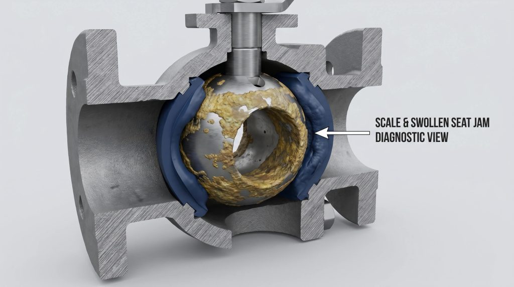
When a manual lever fails, it often points to severe internal problems such as chemical attack, seat swelling, or mineral scale encrustation. If a new handle requires excessive force to cycle immediately after installation, the valve seats have likely swelled or trapped debris.
Elastomer Swelling and Chemical Incompatibility
Certain elastomer and fluoropolymer seat materials expand when exposed to incompatible chemical compounds, increasing the sealing preload force against the ball and seizing the assembly. In these situations, forcing the valve will only cause another failure. Technicians must inspect the media compatibility charts to ensure the valve’s internal seat materials are designed for the specific process chemical.
Stem Packing Wear and Scoring
If fluid is weeping from the packing gland even after tightening the packing nut, the stem itself may be worn, out-of-round, or physically scored. If the sealing surfaces are compromised, replacing the handle will not stop fugitive emissions. In such cases, plants must replace the entire unit with heavy-duty alternatives like industrial globe valves for throttling or high-integrity ball valves designed for aggressive service.
FAQ Section
Can I use a standard pipe wrench to operate a valve with a broken handle?
No, using standard pipe wrenches on a valve stem is highly discouraged except in extreme, immediate emergencies. Pipe wrenches feature sharp, hardened steel teeth that bite into metal, which will easily gouge, score, or deform the flat profiles of the stem. This surface damage will quickly destroy the internal PTFE stem packing as the stem is rotated, leading to localized packing leaks. If a wrench must be used in an emergency, select an adjustable flat-jaw wrench and apply force concentrically.
What is the typical lifespan of an industrial stainless steel valve handle?
A high-quality ASTM A240 stainless steel handle typically matches the service life of the valve itself, often exceeding ten to fifteen years. Unlike zinc-plated carbon steel or plastic-coated handles, stainless steel resists atmospheric moisture, salt spray, and mild chemical exposure without losing its mechanical properties. However, in extremely aggressive chemical environments—such as marine splash zones—even stainless steel must be inspected periodically for localized pitting.
How does galvanic corrosion occur on a ball valve handle assembly?
Galvanic corrosion occurs when a less noble handle material, such as zinc-plated carbon steel, is directly paired with a noble stainless steel stem in a humid or corrosive environment. The moisture acts as an electrolyte, establishing a galvanic cell where the handle behaves as an anode and sacrifices itself to protect the noble stainless steel stem. This results in rapid thinning and weakening of the handle’s connection socket, culminating in sudden mechanical shear under standard operational force.
Does a broken handle mean the internal ball is seized?
Not in all cases, but a broken handle is a strong indicator that internal operating friction has exceeded safety limits. While mechanical fatigue or corrosion can cause a handle to break under normal operating loads, the vast majority of failures occur when operators attempt to force a valve that is partially stuck. This is often caused by debris accumulation behind the seats, polymer crystallization, or seat swelling due to chemical incompatibility.
What are the advantages of replacing manual levers with pneumatic actuators?
Replacing manual levers with pneumatic actuators eliminates human over-torque errors, provides balanced concentric forces, and enables automated process control. Pneumatic actuators utilize controlled air pressure to stroke the valve, applying balanced torque without inducing harmful lateral bending moments on the stem. Additionally, they prevent operators from using unauthorized leverage tools and protect the internal valve components through torque-limiting features.
Conclusion and Prevention Checklist
A sheared valve lever is a critical operational warning sign that points to elevated stem torque, corrosion, or incorrect material specification. While temporary override tools can restore flow control during a production shift, long-term system integrity depends on engineering-led material selection, calculating strict leverage limits, and evaluating automated upgrades. By transitioning from manual overrides to high-durability alloy components or automated control loops, plants can minimize maintenance hazards and ensure uninterrupted production.
Core Action Checklist for Maintenance Managers:
- [ ] Isolate and Depressurize: Prioritize safety by ensuring complete line isolation and pressure relief before performing any mechanical maintenance on the valve.
- [ ] Use Parallel-Jaw Tools: Avoid pipe wrenches; utilize machined, parallel-jaw tools to protect the precision-ground surfaces of the valve stem.
- [ ] Upgrade Material Specs: Replace standard carbon steel or plastic handles with ASTM A240 316 stainless steel in highly corrosive or coastal environments.
- [ ] Calculate Leverage Limits: Ensure manual handle lengths are designed to prevent operators from exceeding 50% of the stem’s MAST value.
- [ ] Consider Automation: Transition critical, high-cycle, or hard-to-reach manual lines to automated integrated flow control solutions to eliminate physical over-torque risks and enable precise remote management.