
Installing a check valve before the ball valve is typically the optimal piping sequence for standard pump discharge lines to facilitate downstream isolation and simplified inline maintenance. However, selecting the correct check valve before or after ball valve configuration often presents a frustrating engineering puzzle for pipeline designers who must balance asset protection against severe water hammer risks and unexpected system downtime. Operating a processing facility with an incorrect or unverified valve sequence accelerates seat degradation, compromises safety barriers, and forces expensive emergency shutdowns. To resolve these operational challenges, Ruitoflow provides precision-engineered flow solutions designed to stabilize high-pressure piping manifolds. This engineering guide analyzes the hydraulic tradeoffs and mechanical design criteria governing both installation sequences, enabling procurement managers and engineering teams to make highly informed, standard-compliant pipeline layout decisions.
Introduction to Ball and Check Valve Integration
Establishing a highly reliable flow loop within process piping systems requires a comprehensive understanding of how downstream pressure isolation and automatic backflow prevention mechanisms interact. While each valve class possesses a distinct mechanical design and functional profile, their physical proximity means that the hydraulic wake of one directly influences the operating lifespan and sealing integrity of the other. Consequently, the relative placement of these components is not merely a drafting detail but a critical process decision that directly impacts lifecycle costs.
Defining the Functional Roles of Ball and Check Valves
In typical industrial process loops, ball valves are deployed as the primary means of manual or automated isolation, offering quarter-turn operation and robust structural integrity. Their spherical design minimizes flow restriction when fully open, though they are inherently ill-suited for continuous flow throttling due to localized seat erosion. These isolation units are designed to withstand full differential pressures over extended periods of inactivity without suffering from significant mechanical creep.
Conversely, industrial check valves operate as self-actuating safety devices that prevent reverse fluid migration without requiring external electrical or pneumatic actuation. By utilizing pressure differentials across the internal disc or piston, these valves seal dynamically as soon as upstream head pressure falls below the spring tension or gravity-assisted seating limit. Integrating both valves into a single pipeline spool provides a robust dual-barrier safety configuration that safeguards upstream machinery.
The Core Engineering Dilemma of Component Sequencing
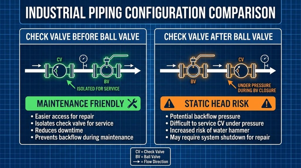
The central challenge in configuring inline control systems is determining whether the dynamic backflow barrier should precede or follow the primary isolation valve. Placing the check valve first safeguards the downstream isolation seat from high-velocity transient reverse flows but complicates scheduled valve maintenance. Alternatively, installing the check valve downstream exposes it to static line pressures but simplifies localized servicing of the pump discharge.
Engineers must evaluate the specific physical behaviors of the process fluid, such as density, velocity, and solid content, alongside maintenance access protocols. Choosing an incorrect layout often induces high-frequency disk flutter, accelerated seat degradation, and severe piping vibration. Achieving a balanced design requires looking beyond simple flow schematics and evaluating transient hydraulic behaviors under various emergency shutdown scenarios.
Scenario A: Check Valve Installed Before Ball Valve
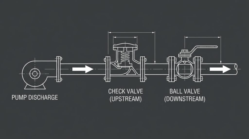
Configuring the pipeline with the non-return valve upstream of the isolation mechanism is a highly favored engineering layout for single-pump continuous process lines. Under this arrangement, fluid exiting the pump discharge nozzle passes directly through the check valve before moving through the manual isolation valve and into the main system header. This sequence provides distinct operational benefits regarding valve servicing while minimizing long-term exposure to backpressure under nominal operating conditions.
Upstream Placement in Pump Discharge Lines
In continuous-flow networks, the upstream placement of the check valve positions it as the immediate receiver of high-velocity fluid leaving the pump impeller. The velocity profile at this point is frequently characterized by high turbulence, which can exert uneven dynamic forces across the check valve disc. Positioning the valve here allows the downstream quarter-turn ball valves to remain isolated from the highest turbulent energies when operating in the fully open state.
This sequence is particularly effective in high-pressure municipal water distribution, wastewater management, and chemical processing facilities where single-pump loops predominate. The check valve acts as a mechanical buffer, preventing high-velocity backflow columns from striking the ball valve’s delicate polymer or elastomeric seats during sudden shutdowns. Consequently, the downstream ball valve experiences a much more stable pressure transition during normal process cycles, ensuring high operational reliability.
Advantages for System Maintenance and Safety
The paramount advantage of placing the check valve upstream of the isolation ball valve is the ease and safety of scheduled maintenance. When the check valve’s internal springs, discs, or hinge pins require inspection or replacement, the downstream ball valve can be closed. This action completely isolates the check valve from the high static head pressure of the downstream header network.
This design allows maintenance crews to depressurize and open the check valve body without draining the entire downstream piping network or halting parallel headers. It significantly reduces the volume of process fluid that must be flushed, lowering chemical disposal costs and minimizing environmental risks. Additionally, this layout permits the safe installation of bleed and drain valves within the isolated spool, in full alignment with plant safety standards.
Risks of Pressure Surge and Vibration Exposure
While maintenance-friendly, this layout exposes the check valve to intense mechanical vibration and hydraulic pulsations exiting the pump. If the spatial distance between the pump discharge nozzle and the check valve is insufficient, the turbulent velocity profile will induce rapid, high-frequency disk oscillation. This continuous chattering accelerates the wear of the internal hinge pins, bushings, and seats, which can lead to premature mechanical failure.
Furthermore, a check valve positioned too close to the pump may slam shut violently during sudden power interruptions, creating localized water hammer. The resulting pressure wave travels backward, potentially cracking the pump casing or damaging upstream flanged connections. To mitigate these risks, piping designers must incorporate adequate straight pipe runs to allow the flow velocity profile to stabilize before it enters the check valve.
Scenario B: Check Valve Installed After Ball Valve
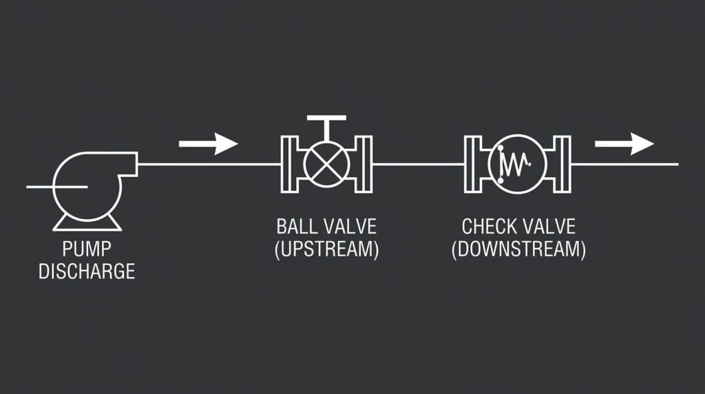
The alternative layout places the isolation ball valve immediately after the pump discharge, with the check valve positioned downstream, closer to the main header line. While this layout is less prevalent in standard single-pump installations, it is frequently specified in complex multi-pump parallel manifolds and standby pump configurations where backpressure management is the primary operational concern during maintenance windows.
Downstream Configuration for Inline Protection
In parallel pumping systems where multiple pumps discharge into a common manifold, a downstream check valve protects the idle pump loop. When Pump A is operating and Pump B is on standby, the check valve on Line B remains closed to prevent fluid from backflowing into the standby assembly. Placing the check valve downstream of the ball valve isolates both the pump and the ball valve from continuous header backpressure.
This layout is highly beneficial when the primary risk is downstream line rupture or fluid back-migration from high-head distribution networks. By isolating the ball valve from continuous high-pressure backflow, this configuration prevents slow, high-pressure seepage through the ball valve seats during standby periods. It ensures that the pump remains completely protected from reverse rotation caused by backward fluid flow.
Advantages for Valve Servicing and Replacement
From a pump-servicing perspective, placing the ball valve upstream provides a reliable primary barrier directly at the pump’s discharge flange. When the pump assembly requires major repairs, seal replacements, or complete swap-outs, the ball valve can be closed to isolate the pump. This allows the pump to be disconnected and serviced safely without risking fluid leakage from the upstream line.
Furthermore, this configuration prevents high-head backpressure from acting on the pump casing during extensive maintenance turnarounds. It allows operators to service the pump in a completely depressurized environment, even if the downstream check valve experiences minor seat leakage. This layout is especially useful in facilities handling non-hazardous fluids where pump wear is significantly higher than valve wear.
Disadvantages Regarding Static Head Backflow
The critical drawback of this layout is that servicing the check valve requires a complete shutdown and depressurization of the downstream header. Because the check valve is positioned downstream of the isolation ball valve, closing the ball valve only isolates the pump, leaving the check valve exposed to full header pressure. To perform any maintenance on the check valve, operators must drain the entire downstream distribution network.
To bypass this severe operational limitation, engineering contractors must install a secondary isolation valve downstream of the check valve. This creates a double-block-and-bleed layout, which significantly increases the spatial footprint, structural weight, and procurement costs of the piping assembly. Consequently, this configuration is generally avoided in single-pump systems unless redundant isolation is mandated by strict process safety regulations.
Key Technical Variables in Placement Decisions
Selecting the most effective valve sequencing requires a rigorous assessment of process variables, piping geometries, and fluid behaviors. Designers cannot rely on a single layout for all systems, as high pressures, variable velocities, and corrosive or particulate-laden media introduce distinct physical stresses. A detailed analysis of these variables is necessary to prevent premature valve fatigue and optimize system performance.
Fluid Media, Pressure Ratings, and Flow Velocity
The physical properties of the process fluid heavily influence both component selection and relative positioning. For instance, abrasive slurries or high-viscosity fluids can cause suspended solids to settle in valve cavities, jamming internal check mechanisms. In these challenging services, utilizing self-cleaning isolation systems like high-performance butterfly valves or specialized gate valves is common, and check valves must be placed where turbulence helps clear particulate deposits.
Pressure ratings, ranging from ASME Class 150 to Class 2500, dictate the required wall thicknesses and flange specifications of the valve housings. High-pressure loops generate massive kinetic forces during transient shutdown events, meaning that flow velocities must be carefully regulated. If fluid velocity exceeds nominal design limits (typically 2.5 m/s), the shockwave generated by a closing check valve can cause structural damage to downstream joints.
Piping Geometry and Water Hammer Risk Mitigation
Water hammer is a destructive pressure wave caused by the sudden deceleration of a moving fluid column when a valve closes abruptly. The magnitude of this pressure surge is directly proportional to the length of the fluid column and its velocity. Placing the check valve upstream of the ball valve minimizes the length of the trapped fluid column, thereby reducing the amplitude of transient shockwaves.
Piping geometry, including elbows, reducers, and tees, alters the fluid’s velocity profile and introduces localized turbulence. Installing a check valve immediately downstream of an elbow is highly discouraged, as the asymmetrical velocity profile causes the valve disc to open unevenly. This uneven force induces severe mechanical wear on the hinge pin, leading to premature leakage and potential mechanical binding of the check mechanism.
Industry Standards and Piping Layout Best Practices
Adhering to recognized global standards ensures that pipeline designs are safe, reliable, and compliant with regulatory mandates. Standard-setting bodies such as ASME, API, and ISO provide detailed design rules that establish minimum wall thicknesses, pressure-temperature ratings, and physical spacing criteria. Integrating these best practices into the layout phase minimizes design errors and streamlines the plant commissioning process.
ASME B31.3 and API RP 520 Layout Guidelines
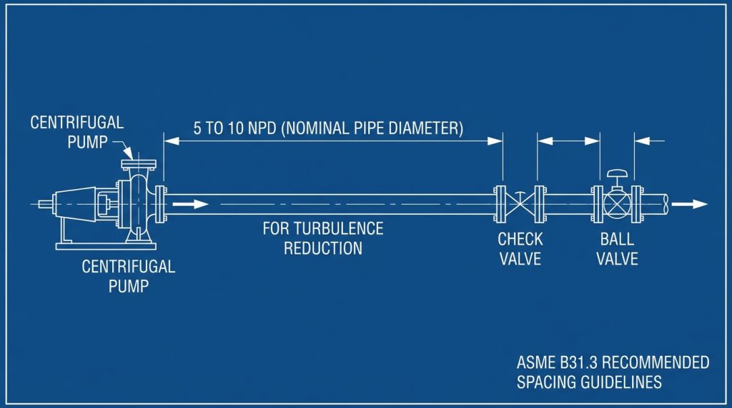
According to major process piping codes such as ASME B31.3, isolation and safety systems must be arranged to limit overpressure hazards and facilitate safe maintenance. Standard practice for pump discharge lines recommends placing the check valve between the pump and the isolation valve. This alignment is codified because the check valve, as a dynamic device with moving parts, is classified as a wearing component requiring more frequent maintenance than a manual ball valve.
Additionally, API RP 520 Part II outlines design guidelines for pressure-relieving systems, emphasizing that valves must be positioned to prevent excessive pressure drops. API 6D testing standards also establish strict leakage criteria for pipeline valves. Ensuring that both the ball and check valves comply with these strict testing protocols is vital for maintaining the structural safety and environmental compliance of high-pressure fluid networks.
Horizontal vs. Vertical Orientation Rules
While ball and butterfly valves can typically operate consistently in any physical orientation, check valves rely heavily on gravity or spring tension to function correctly. Swing check and lift check valves are designed for horizontal pipelines, with their bonnets facing upward to ensure symmetrical disc closing. If installed in vertical lines, swing checks must only be used where the flow direction is upward, as gravity must assist the closing action.
Vertical-downward flow configurations are highly problematic and should generally be avoided for standard swing check valves, as the disc can remain floating, causing backflow. In these challenging vertical-down layouts, specialized spring-assisted silent check valves are required to ensure rapid, positive closure. Piping engineers must carefully verify the intended flow direction and spatial constraints before selecting specific check valve models for procurement.
Engineering Selection and Procurement Guidelines
Procuring the correct valve combination requires close cooperation between engineering designers, project managers, and certified manufacturers. Sourcing high-quality components made from compliant material grades is essential for preventing premature pipeline degradation and ensuring long-term operational safety. Procurement teams must look beyond initial cost and evaluate the total lifecycle value of the valve assembly.
Specifying the Right Valve Metallurgy and Trim
Achieving high-integrity sealing requires matching the valve metallurgy to the specific chemical properties and temperatures of the process media. For standard non-corrosive water or hydrocarbon services, carbon steel bodies conforming to ASTM A216 WCB are highly effective and economical. In contrast, highly corrosive or cryogenic chemical lines require stainless steel grades such as ASTM A351 CF8M or duplex alloys to prevent localized pitting and erosion.
Sealing seat materials must also be carefully selected based on the operating temperature range. Soft seats like reinforced PTFE (RPTFE) provide reliable sealing but are limited to moderate temperatures. For high-temperature steam or abrasive slurry services, metal-to-metal seated valves utilizing hard-facing alloys like Stellite are necessary to withstand mechanical wear and thermal expansion without compromising sealing performance.
Minimizing Cavitation and Turbulence Risks
Cavitation is a destructive physical process that occurs when localized pressure drops below the fluid’s vapor pressure, causing vapor bubbles to form and collapse violently. This action deforms metal surfaces, leading to rapid valve erosion and structural failure. To minimize cavitation risk, piping designers must ensure that fluid velocities remain within standard laminar parameters and that check valves are placed away from turbulence zones.
Best engineering practices suggest maintaining a straight pipe run of at least 5 to 10 nominal pipe diameters (5D to 10D) between the pump discharge and the check valve inlet. Additionally, a straight run of at least 3 nominal pipe diameters (3D) should separate the check valve from the downstream ball valve. This layout ensures a stable velocity profile, preventing uneven forces on the check valve disc and extending the lifespan of the entire system.
Engineering Comparison Matrix
The decision-matrix below highlights the key engineering tradeoffs between the two placement scenarios based on physical piping configurations and operational parameters.
| Evaluation Parameter | Scenario A: Check Valve Upstream (Pump -> Check -> Ball) | Scenario B: Check Valve Downstream (Pump -> Ball -> Check) |
|---|---|---|
| Primary Suitability | Single-pump configurations and continuous process loops. | Parallel pumping systems and manifolds with standby units. |
| Maintenance Accessibility | Excellent. Downstream ball valve isolates header pressure for check valve service. | Poor. Requires full downstream header depressurization or extra isolation valves. |
| System Downtime | Minimal; check valve can be serviced while parallel headers remain active. | Substantial; requires broad system shutdown unless bypassed. |
| Pump Backflow Protection | Optimal; immediate seating prevents rotor spinning upon pump shutdown. | Moderate; protects the pump but leaves the ball valve exposed to pressure surges. |
| Piping Spacing Footprint | Moderate; requires standard straight runs to stabilize turbulent pump discharge. | Compact; but can concentrate structural weight on piping flanges. |
| Standard Compliance | Aligns fully with standard ASME B31.3 layout recommendations. | Requires special process justification under standard piping codes. |
High-Value Engineering FAQs
FAQ 1: Is a check valve before or after ball valve layout better for slurry applications?
Answer: Generally, the check valve before ball valve configuration is superior for slurry applications. Placing the check valve upstream of the ball valve ensures that the turbulent flow exiting the pump keeps solid particulates in suspension around the check disc. If the ball valve is placed first and left closed, solids will rapidly settle in the dead space of the downstream check valve body, jamming the hinge mechanism and preventing tight backflow sealing upon restart.
FAQ 2: Can a wafer-type check valve be bolted directly to a flanged ball valve?
Answer: No, bolting a wafer check valve directly to a flanged ball valve is highly discouraged in professional piping design. Wafer-style check valves require radial clearance for their internal dual plates or swing discs to open fully into the pipeline. Bolting them directly to a ball valve flange restricts this movement, causing the check disc to strike the ball or the exit neck, which results in flow restriction and severe mechanical damage.
FAQ 3: How does thermal expansion affect fluid trapped between a closed ball valve and a check valve?
Answer: Typically, fluid trapped between a closed ball valve and a downstream check valve experiences rapid thermal expansion under ambient temperature variations. This localized heating can generate extreme hydrostatic pressure within the isolated spool, leading to flange gasket blowouts, seat deformation, or piping rupture. Incorporating a small pressure bypass or bleed valve is highly recommended in these setups.
FAQ 4: Which ASME standard governs the design and testing of these valve bodies?
Answer: Primarily, ASME B16.34 establishes the standard pressure-temperature ratings, wall thicknesses, and dimensional tolerances for cast and forged valve bodies. Additionally, API 6D and API 598 govern the exact testing procedures, including high-pressure hydrostatic and low-pressure pneumatic seat testing, which are required to verify the sealing integrity of industrial valves.
Conclusion
Optimizing process piping layouts requires a careful assessment of whether to position the check valve before or after ball valve isolation systems. For the vast majority of single-pump discharge lines, placing the check valve upstream of the ball valve is the superior layout, offering unmatched maintenance accessibility, high pump protection, and reliable water hammer mitigation. This layout allows operators to service the check valve safely without draining the main header, reducing overall plant downtime and maximizing process security.
As a premier industrial valve manufacturer, RUITO FLOW CONTROLS delivers heavy-duty, certified flow solutions engineered to withstand demanding operating pressures and aggressive media. Our advanced manufacturing facilities utilize strict testing protocols compliant with API 598 and API 6D standards, ensuring high-integrity performance and long-term durability. For custom engineering configurations or comprehensive project support, contact our engineering team today to consult with our technical sales specialists.