A butterfly valve drawing symbol visually represents flow control mechanisms within industrial schematics. Designing complex pipelines frustrates many engineers when component marks lack absolute clarity. Misinterpreted diagrams cause massive fabrication delays and blown budgets. Standardized graphical notation provides absolute certainty for your whole team. Mastering the butterfly valve drawing symbol prevents expensive misunderstandings entirely. Professionals demand accurate blueprints.

1. What Is The Standard Butterfly Valve Drawing Symbol?
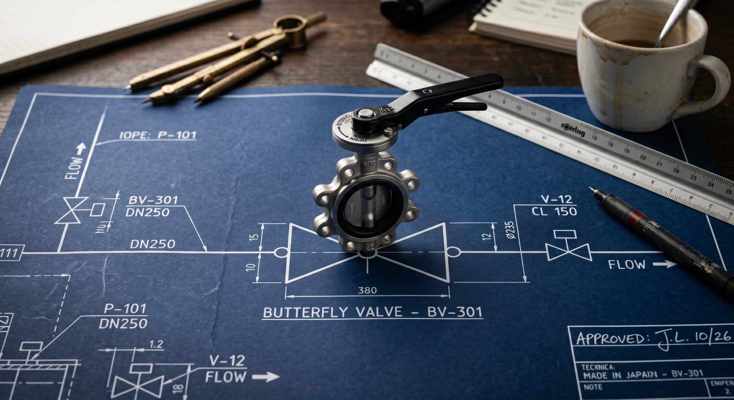
The basic butterfly valve drawing symbol features two converging triangles meeting at a central point. We integrate the butterfly valve drawing symbol within all technical schematics constantly. This distinct bowtie shape differentiates this specific component from standard gate or globe variants instantly. Engineers recognize this graphic immediately during rapid schematic reviews.
Why Does Geometry Matter?
Geometric precision reduces cognitive load for busy piping designers. Here is the deal: clear shapes accelerate your entire drafting workflow immensely.
- Converging lines indicate fluid restriction points.
- Central nodes represent rotating disc elements.
- Parallel outer strokes denote flanged connections clearly.
Key Takeaway: Memorizing this primary graphic prevents critical installation mistakes across your manufacturing facility. Your team works much faster when everyone understands system blueprints perfectly.
| Feature | Visual Form | Mechanical Meaning |
|---|---|---|
| Triangles | Bowtie outline | Flow restriction |
| Node | Center dot | Rotating shaft |
| Borders | Vertical lines | Pipe connection |
Analyzing these components reveals how drafters pack massive mechanical data into a minimal footprint.
2. How To Read A P\&ID Butterfly Valve Drawing Symbol?
Reading a P\&ID butterfly valve drawing symbol requires understanding adjacent instrumentation lines and modifier marks. You must identify specific actuator attachments resting above the main bowtie graphic. These tiny additions dictate whether the mechanism operates manually or automatically.
What Do The Modifiers Mean?
Modifiers change the fundamental operational definition of the component entirely. You might be wondering: how do these tiny marks affect actual field operations?
- A simple T-line indicates a manual handwheel actuator.
- A square box with an ‘M’ denotes motor operation.
- A half-circle signifies a pneumatic diaphragm setup.
Key Takeaway: Accurately interpreting these secondary markings guarantees proper hardware selection during the procurement phase. Your maintenance crew relies heavily on these specific P\&ID details.
| Actuator Mark | Graphic Addition | Operation Method |
|---|---|---|
| T-Line | Top perpendicular bar | Manual turning |
| M-Box | Square containing M | Electric motor |
| Half-Circle | Dome above center | Pneumatic air |
Reviewing these actuator marks prevents selecting incompatible control systems for your fluid network.
3. Why Use A Specific Butterfly Valve Drawing Symbol?
Using a specific butterfly valve drawing symbol establishes a universal engineering language across different global teams. A standardized butterfly valve drawing symbol eliminates dangerous guesswork from complex construction projects. Contractors across different continents interpret the exact same mechanical meaning effortlessly.
How Does Standardization Help?
Standardization keeps massive industrial projects on schedule and under budget constantly. What is the real story? Unified drafting languages save companies millions in rework costs.
- Drafting errors drop significantly when using approved libraries.
- New engineers onboard much faster with standard charts.
- Regulatory audits proceed smoothly with recognized notations.
Key Takeaway: Adhering strictly to established notations protects your project from catastrophic misinterpretations. You protect your baseline profit margins by enforcing strict drafting rules.
| Benefit Category | Direct Impact | Cost Saving |
|---|---|---|
| Training | Faster onboarding | High |
| Compliance | Fewer audit failures | Medium |
| Construction | Reduced rework | Massive |
Evaluating these benefits shows exactly why massive corporations mandate strict drafting guidelines globally.
4. What Actuators Match The Butterfly Valve Drawing Symbol?
Several distinct actuators pair seamlessly with the foundational butterfly valve drawing symbol on modern schematics. You will frequently encounter hydraulic cylinders attached to the central rotating shaft notation. Each power source requires a distinct secondary graphic placed directly above the main icon.
How Do Power Sources Look?
Different power sources dramatically alter the final schematic appearance. This is where it gets interesting: power symbols often overlap with electrical diagrams.
- Hydraulic lines use a distinct square with fluid indicators.
- Solenoid setups feature a small zig-zag line.
- Gear operators utilize a small circular gear icon.
Key Takeaway: Recognizing these specific power indicators helps your team plan electrical and pneumatic routing accurately. Your facility requires coordinated infrastructure to support these varied actuator types.
| Power Source | Schematic Indicator | Infrastructure Need |
|---|---|---|
| Hydraulic | Fluid square | Pressurized oil |
| Solenoid | Zig-zag line | Electrical wire |
| Gearbox | Gear icon | Manual access |
Mapping these power requirements early prevents costly infrastructure upgrades late in the construction cycle.
5. Can A Butterfly Valve Drawing Symbol Vary By Region?
A butterfly valve drawing symbol sometimes exhibits minor stylistic differences depending on the regional standard applied. You might notice slight variations in the butterfly valve drawing symbol when reviewing European DIN standards versus American ANSI formats. These subtle changes rarely alter the core bowtie geometry completely.
What Are The Regional Differences?
Regional differences mostly affect the surrounding piping connection indicators rather than the main body. Ready for the good part? Modern CAD software automatically translates these regional differences for you.
- ANSI diagrams often use solid lines for flanges.
- DIN schematics might utilize varied line weights.
- JIS formats occasionally alter the central node size.
Key Takeaway: Maintaining awareness of these regional quirks prevents confusion when collaborating with international manufacturing partners. You secure seamless global operations by understanding these minor graphical deviations.
| Standard | Region | Notable Quirk |
|---|---|---|
| ANSI | North America | Solid flange lines |
| DIN | Europe | Varied line weights |
| JIS | Japan | Modified node size |
Comparing these global formats highlights the resilience of the foundational bowtie design across all borders.
6. How Does A 3D Butterfly Valve Drawing Symbol Work?
A 3D butterfly valve drawing symbol provides depth and spatial orientation within complex modeling software environments. You use a 3D butterfly valve drawing symbol to check for physical interference with adjacent piping structures. These advanced models contain massive amounts of metadata regarding weight and material specifications.
Why Transition To 3D Modeling?
Three-dimensional drafting solves physical space limitations before actual construction begins. Here is the kicker: spatial awareness prevents contractors from installing components backwards.
- Drafters rotate models to verify handle clearance.
- Software calculates exact fluid pressure drops automatically.
- Procurement teams extract material lists directly from the model.
Key Takeaway: Upgrading to multidimensional drafting tools drastically reduces physical clashes during field assembly. Your engineering department achieves higher precision using these advanced spatial representations.
| Model Type | Primary Function | Data Output |
|---|---|---|
| 2D Wireframe | Basic layout | Material list |
| 3D Surface | Clearance check | Spatial volume |
| 3D Solid | Stress analysis | Weight metrics |
Reviewing these modeling tiers proves that multidimensional drafting outpaces traditional flat drawings completely.
7. What Errors Occur With A Butterfly Valve Drawing Symbol?
Drafting mistakes involving a butterfly valve drawing symbol usually stem from improper scaling or missing actuator tags. We occasionally see the butterfly valve drawing symbol drawn backwards relative to the intended fluid direction. Such errors cause massive headaches during the final system commissioning phase.
How To Prevent Common Drafting Mistakes?
Rigorous peer review catches the majority of spatial and proportional drawing mistakes quickly. What is the real story? Automated software checks now eliminate many human drafting errors instantly.
- Always verify the flow direction arrow matches the valve orientation.
- Double-check that the actuator size matches the pipe diameter.
- Confirm flange connections align perfectly with adjacent pipes.
Key Takeaway: Implementing strict quality control checklists saves your fabrication team from correcting expensive layout mistakes. You protect your project timeline by catching these simple graphical errors early.
| Error Type | Visual Symptom | Field Consequence |
|---|---|---|
| Reversal | Pointing upstream | Flow disruption |
| Scaling | Too small | Wrong part ordered |
| Alignment | Disconnected lines | Weld failure |
Tracking these common failures helps drafting managers design better training programs for junior engineers.
8. How To Draw A Basic Butterfly Valve Drawing Symbol?
Drawing a basic butterfly valve drawing symbol by hand requires only a straightedge and precise angle measurements. You start your butterfly valve drawing symbol by sketching a horizontal centerline representing the main fluid pipe. Accuracy remains paramount even when sketching preliminary concepts on scrap paper.
What Are The Exact Drawing Steps?
Following a structured method produces clean and readable schematics every single time. This is where it gets interesting: muscle memory makes drawing these icons incredibly fast over time.
- Draw two identical triangles pointing towards each other.
- Ensure the points touch exactly on the pipe centerline.
- Add vertical lines at the wide bases for flanges.
Key Takeaway: Mastering manual sketching allows engineers to communicate complex ideas rapidly during sudden field meetings. Your ability to sketch accurately builds immediate trust with onsite fabrication crews.
| Step | Action | Result |
|---|---|---|
| 1 | Centerline | Flow path established |
| 2 | Triangles | Valve body formed |
| 3 | Vertical bars | Connections defined |
Practicing these simple steps builds foundational drafting skills required for advanced schematic creation.
9. Where To Find A CAD Butterfly Valve Drawing Symbol?
Locating a reliable CAD butterfly valve drawing symbol saves drafters hundreds of hours of manual design work. The best butterfly valve drawing symbol libraries exist within verified manufacturer databases or premium engineering portals. Downloading pre-made blocks guarantees exact proportional accuracy for your final blueprints.
How To Choose The Right Block Library?
Selecting a high-quality block library prevents corrupted files from crashing your expensive design software. Ready for the good part? Many top-tier manufacturers offer these precise digital assets completely free of charge.
- Verify the file format matches your specific CAD version.
- Check that the block includes all necessary metadata tags.
- Ensure the visual style matches your internal company standards.
Key Takeaway: Leveraging existing digital assets allows your engineering team to focus on system design rather than icon creation. You dramatically accelerate project delivery timelines by utilizing verified component libraries.
| Source Type | Quality | Cost |
|---|---|---|
| Manufacturer | Excellent | Free |
| Premium Portal | Very Good | Paid subscription |
| User Forum | Variable | Free |
Auditing these digital sources guarantees your team only uses safe and accurate drafting components.
10. How To Verify Your Butterfly Valve Drawing Symbol?
Verifying a butterfly valve drawing symbol involves cross-referencing the schematic against the master material list thoroughly. You must confirm every butterfly valve drawing symbol perfectly matches the physical hardware intended for installation. This final check prevents catastrophic failures during the initial system pressurization tests.
What Is The Final Audit Process?
A rigorous final audit requires an independent engineer to review the completed schematics line by line. Here is the deal: fresh eyes catch subtle graphical mistakes that the original drafter missed completely.
- Trace every fluid path from origin to destination manually.
- Verify all actuator marks match the electrical control schematics.
- Confirm all pressure ratings align with the chosen graphical symbol.
Key Takeaway: Executing a strict verification protocol secures your facility against unexpected leaks or pressure drops. Your commitment to accurate documentation protects both your workers and your heavy machinery.
| Verification Step | Focus Area | Goal |
|---|---|---|
| Line Tracing | Flow continuity | Prevent dead ends |
| Cross-Reference | Electrical plans | Match power needs |
| Rating Check | Metadata | Ensure safety limits |
Completing this audit process delivers ultimate peace of mind before any physical construction begins.
Wrapping Up
Standardized graphical notations drastically reduce engineering friction and prevent costly fabrication errors across your facility. Implementing strict drafting rules keeps your industrial projects aligned with international safety standards constantly. Clear blueprints empower your workforce to build complex systems faster and with far greater accuracy. We supply premium flow control components designed specifically for rigorous industrial environments. Let our expertise support your next massive pipeline project from the initial draft to the final pressure test. Feel free to contact us today to upgrade your fluid control infrastructure.
FAQ
Q1: Can I use a generic valve symbol instead of a specific one?
You cannot safely substitute a generic icon for a specific component mark. Generic marks cause dangerous confusion regarding flow control capabilities and actuator requirements during installation.
Q2: What is the best software for generating these specific P\&ID schematics?
AutoCAD and SolidWorks remain the industry standards for generating precise pipeline diagrams. These platforms offer massive pre-built libraries containing perfectly scaled fluid control icons.
Q3: How do I know if the schematic symbol requires a manual or automatic actuator?
You look directly above the central bowtie shape for specific modifier markings. A simple “T” indicates manual operation, while boxes or domes represent motorized or pneumatic power.
Q4: Can I modify the standard graphical icon to fit a crowded blueprint?
You must never alter the fundamental geometry of a standardized engineering icon. Shrinking the overall scale is acceptable, but deleting lines destroys the core mechanical meaning entirely.
Q5: What is the best way to train new drafters on these specific notations?
You should provide comprehensive cheat sheets detailing every recognized graphical variation. Consistent repetition and strict peer reviews build their proficiency rapidly and permanently.