Understanding how ball valve works is essential for ensuring precise flow control, bubble-tight shutoff, and reliable operation in modern industrial piping systems. In high-pressure chemical processing and manufacturing facilities, plant operators routinely grapple with the catastrophic risks of fluid leakage, pressure drops, and sudden downtime. A minor sealing failure or valve seizure can compromise entire process loops, resulting in costly material loss and environmental hazards. Integrating precision-engineered ball valves into these demanding processes provides a robust solution, shielding downstream equipment while maintaining structural and functional pipeline safety under severe operational stress.
Core Engineering Principles: How Ball Valve Works
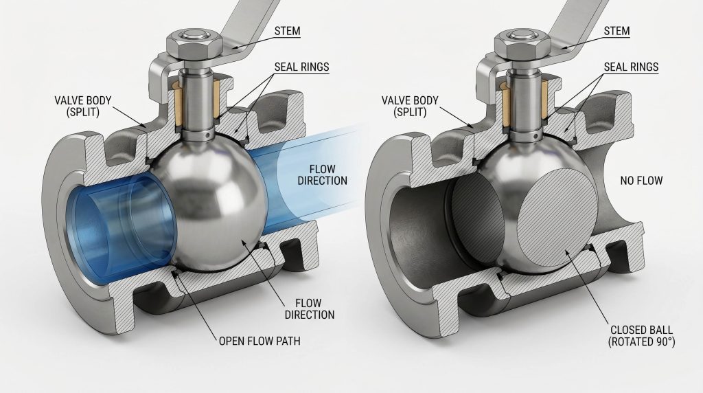
At its core, a ball valve works by rotating a spherical ball with a bored-out flow passage 90 degrees to either allow or block fluid flow. This operational movement is classified as quarter-turn rotary action, meaning the valve changes its state from fully open to fully closed with a single 90-degree turn of the stem. When the valve is in the open position, the bored-out passage, or bore, is aligned parallel to the pipeline, enabling fluid to stream through with minimal flow resistance. When the operator or actuator rotates the stem 90 degrees, the solid portion of the spherical ball is positioned perpendicular to the fluid stream, blocking the passage and arresting the line pressure.
The sealing capability of this mechanism relies on continuous contact between the polished surface of the ball and the surrounding seat rings. As the ball rotates, the seats maintain a tight barrier around the bore, preventing process media from bypassing the closure element. The rate of fluid flow through the valve is governed entirely by the percentage of bore alignment with the pipeline. While primarily designed for quick-acting isolation, specialized ball shapes can be adapted to modulate flow rates, though standard round-bore valves are typically reserved for full isolation.
This quarter-turn design offers significant performance advantages over multi-turn alternatives like gate or globe valves. The rapid cycle speed allows for immediate isolation in critical processes, making them indispensable for emergency shutdown systems. Furthermore, the simple mechanical movement minimizes wear on the internal components, contributing to lower operational torque and an extended service life under normal conditions.
Internal Components of an Industrial Ball Valve
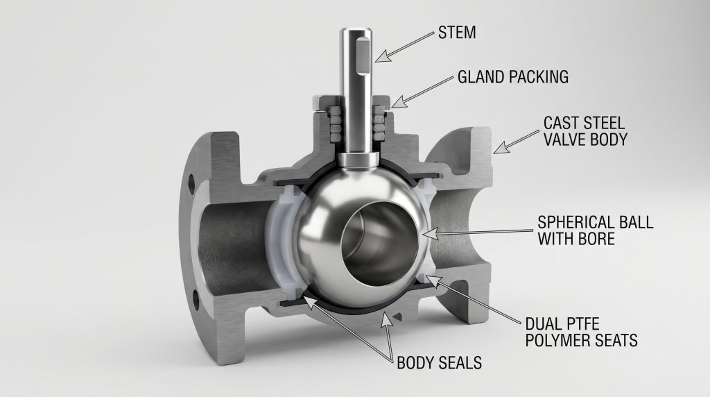
An industrial ball valve comprises several critical components that work in unison to maintain pressure boundary and seal integrity. The mechanical performance of these valves relies heavily on the precise interface between moving parts and static barriers. Each component is engineered to handle dynamic mechanical stresses while preventing process media from escaping into the environment. Understanding these individual elements is crucial for selecting the correct valve specification for highly demanding systems.
The Spherical Ball and Flow Bore
The ball is the central rotary closure element containing a machined cylindrical port or flow bore through its center. Its spherical surface is highly polished to minimize frictional wear against the surrounding seat materials during rotation. The flow bore itself can vary in diameter to match or restrict the pipeline’s flow area depending on the application. This geometry dictates the flow capacity and turbulence levels within the pipeline.
The Stem and Actuation Interface
The stem links the internal spherical ball to the external actuation device, translating mechanical torque into rotational movement. It is typically designed with anti-blowout features to ensure it remains securely in place under high internal pipeline pressures. Dynamic seals around the stem prevent process media from leaking along this moving interface. Proper alignment of the stem prevents uneven wear on both the stem seals and the main ball.
The Seats and Gland Packing
Valve seats provide the sealing interface between the static valve body and the dynamic spherical ball. These seats are pre-loaded during assembly to maintain a continuous contact barrier, preventing fluid bypass when the valve is closed. Gland packing is compressed around the upper stem assembly to act as a primary barrier against fugitive emissions. These packing materials must withstand high cycle rates and temperature fluctuations to prevent environmental leakage.
Floating vs Trunnion Mounted Ball Valve Mechanics
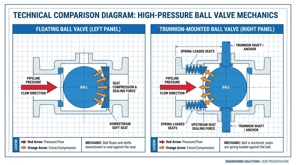
The primary mechanical difference lies in how the ball is supported and how sealing forces are distributed under pipeline pressure. In a floating ball valve design, the ball is suspended on the stem and has some axial freedom of movement. Under upstream line pressure, the ball shifts slightly downstream, pressing against the downstream seat to compress the polymer seal and achieve a bubble-tight shutoff. This self-sealing mechanism is highly effective but increases operating torque as pressure rises, since the downstream seat absorbs the entire fluid load.
Conversely, a trunnion-mounted ball valve anchors the ball securely on a vertical axis using upper and lower trunnion plates or bearings. Under pressure, the ball cannot shift downstream; instead, floating, spring-loaded seat rings are pushed against the stationary ball by upstream fluid pressure and mechanical springs. This design isolates the operating torque from the line pressure, making it optimal for high-pressure, large-diameter systems such as oil and gas transmission pipelines.
Key Takeaway: Floating ball designs utilize pipeline pressure to push the ball downstream to achieve a seal, making them cost-effective for smaller lines. In contrast, trunnion-mounted designs anchor the ball vertically and use spring-loaded seats, reducing operational torque and seal wear in high-pressure or large-scale systems.
Full Bore vs Reduced Bore Flow Optimization
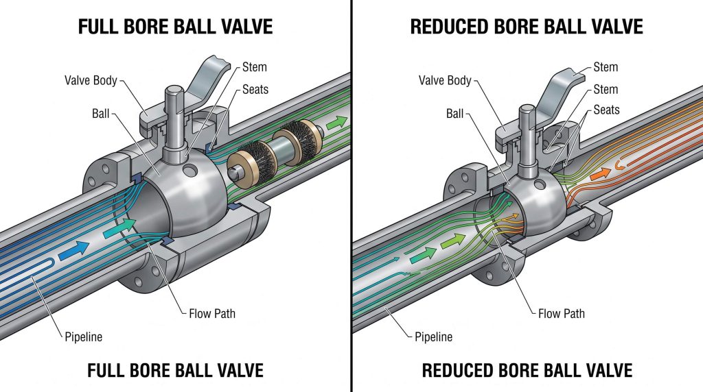
Selecting between full bore and reduced bore ball valves depends on the required flow rate, pressure drop, and pigging capabilities. In a full bore ball valve, the internal diameter of the ball’s flow path matches the inner diameter of the pipeline. This design eliminates flow restriction, keeping friction losses and pressure drop across the valve virtually identical to a straight piece of pipe. These characteristics are essential for pipelines that undergo mechanical cleaning or inspection with pipeline pigging tools.
In a reduced bore ball valve, the flow path through the ball is typically one to two sizes smaller than the inlet and outlet connections. This restricts flow, increases velocity, and creates a measurable pressure drop, but allows for a smaller, lighter, and more cost-effective valve body. While full-bore designs match the flow area of heavy-duty gate valves, their high structural weight means engineers often switch to lightweight high-performance butterfly valves in large-diameter low-pressure utility lines where a minimal pressure drop is still required but budget limits apply.
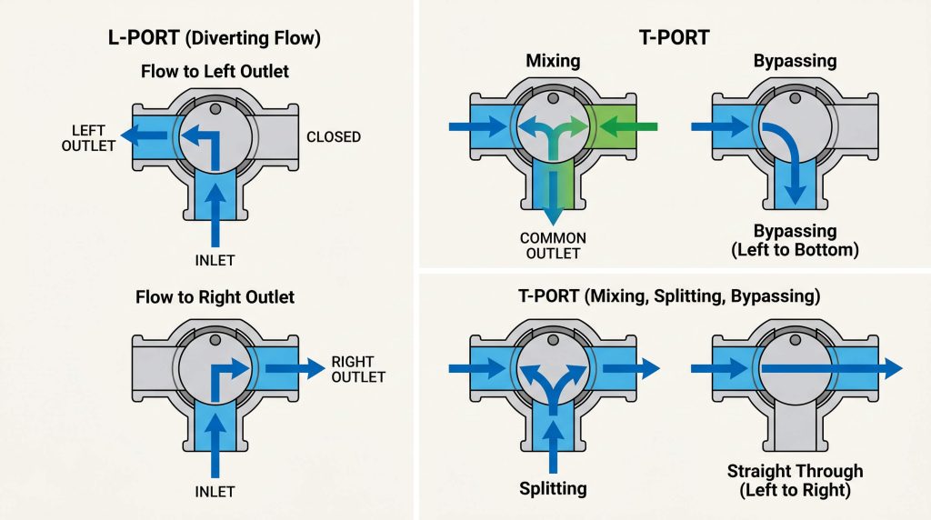
Multi-Port Flow Routing in 3-Way Ball Valves
Multi-port ball valves redirect fluid paths across three or more ports using specialized L-port or T-port ball designs. An L-port ball design is primarily used to divert flow from a single inlet to one of two outlets, and it cannot connect all three ports simultaneously. This design is highly efficient for switching between storage tanks or alternative process lines.
A T-port ball design allows for more complex flow routing, such as mixing two different inlet streams, splitting a single stream into two outlets, or allowing straight-through flow while bypassing the third port entirely. These multi-port configurations significantly reduce the total valve count, piping connections, and footprint in fluid-routing systems. Selecting the correct multi-port layout within the range of precision-engineered ball valves simplifies process flow design and reduces installation costs.
Soft Sealing vs Metal Sealing Seat Technologies
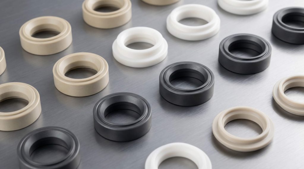
Operating temperature, pressure, and media abrasiveness are the primary drivers when choosing between soft seats and metal seats. Soft seats, typically made from polymers like PTFE, RPTFE, PEEK, or Devlon, provide an excellent bubble-tight seal under rated pressures and low-to-moderate temperatures. However, soft polymer seats are limited by temperature and can be easily eroded by abrasive particles or high-velocity dry gas.
For severe service applications, metal-to-metal hard seating is required. Chromium carbide or tungsten carbide coatings are applied to metallic seat rings and the ball surface. These valves withstand extreme temperatures and handle severe slurries, though they require high-precision grinding to maintain reliable shutoff. In severe abrasive slurries where even metal-seated ball valves face premature erosion, engineers may select specialty plug valves or robust metal-seated configurations to maintain process control.
| Sealing Seat Type | Sealing Performance | Temperature Limits | Media Compatibility | Frictional Torque | Typical Applications |
|---|---|---|---|---|---|
| Soft Seats (PTFE/PEEK) | Designed for bubble-tight, zero-leakage shutoff under rated pressure. | Limited to low-to-moderate operating temperatures. | Highly compatible with clean fluids, chemicals, and gases. | Low frictional torque, requiring smaller actuators. | Clean utility lines, water treatment, low-pressure gases. |
| Metal Seats (Carbide Coatings) | Minimizes leakage risk under high pressure, though small bypass may occur. | Suitable for high-temperature and thermal-shock services. | Excellent resistance to abrasive slurries, solids, and steam. | High frictional torque, requiring larger actuation systems. | Mining slurries, high-temperature steam, crude oil refining. |
Key Takeaway: Choosing between soft and metal seats requires balancing the leak-rate tolerance against the severity of the process environment. While soft seats deliver superior, bubble-tight shutoff in clean utility services, metal seats are mandatory for preserving sealing integrity under high-temperature or highly abrasive slurries.
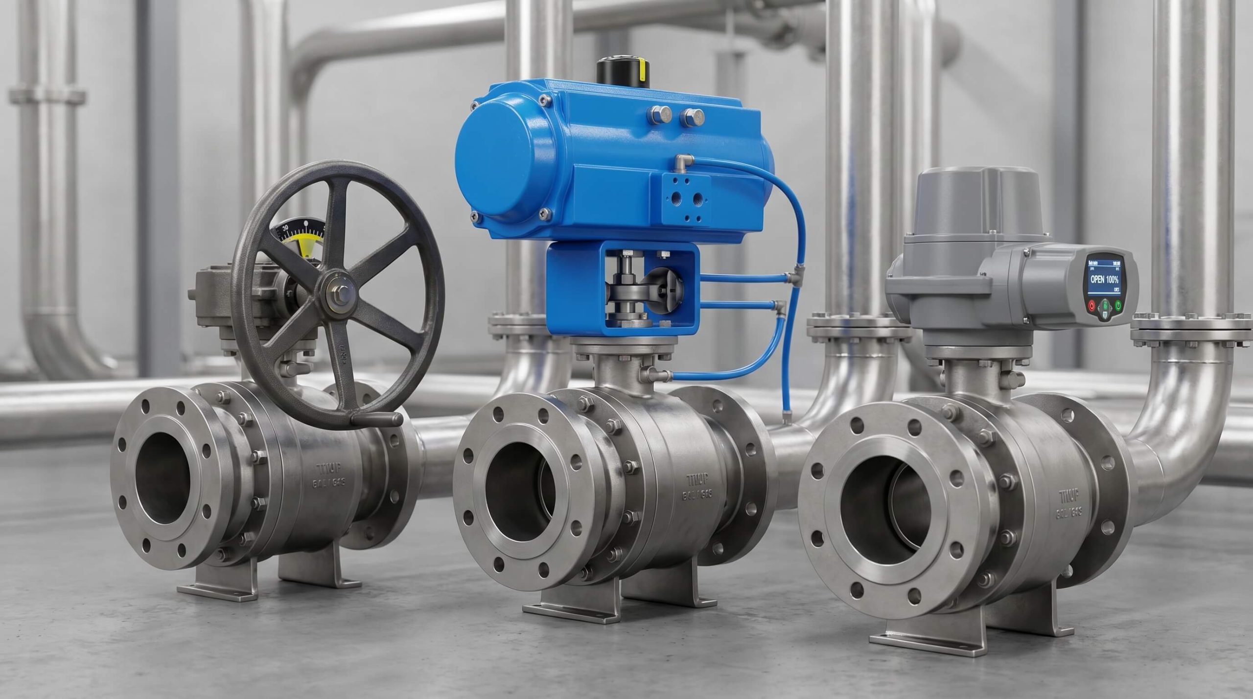
Industrial Ball Valve Actuation and Automation
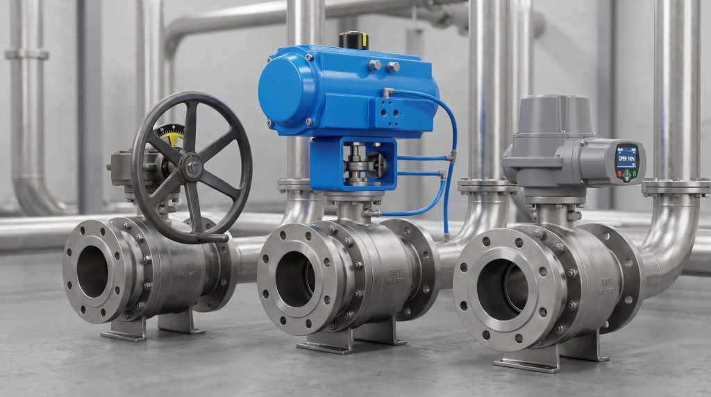
Automated ball valves utilize pneumatic, electric, or hydraulic actuators to enable remote control and safety shutdown functionality. Pneumatic actuators, using either rack-and-pinion or scotch yoke mechanisms, are the industry standard for fast, reliable emergency shutdown (ESD). Scotch yoke actuators are particularly suited for trunnion-mounted valves because they deliver a torque curve that matches the high breakaway torque required to unseat the ball under full differential pressure.
Electric actuators are ideal for precise, slow-moving automation and process modulation where compressed air lines are unavailable. Hydraulic actuators are selected for heavy-duty applications requiring immense torque output, such as large-diameter pipelines in offshore installations. Incorporating automated limit switches, solenoid valves, and smart positioners allows the ball valve to function as a dynamic element within modern distributed control systems (DCS).
FAQ
At what pipeline pressure should I switch from a floating ball valve to a trunnion design?
Transitioning to a trunnion-mounted configuration is generally recommended for pipelines operating at Class 600 or higher, or for larger diameter valves in Class 150 and 300. This is because high fluid pressure acting on a floating ball generates immense force, compressing the downstream seat and creating excessive torque that can damage the seat polymer and require oversized, costly actuators.
Can standard ball valves be used for continuous throttling or flow control?
Standard round-port ball valves are not designed for continuous throttling and should primarily be used for isolation. Operating a standard ball valve in a partially open position concentrates high-velocity flow and turbulence on the exposed edges of the seats, leading to rapid erosion and undermining the valve’s long-term sealing capabilities.
How does a fire-safe design protect pipelines during thermal emergencies?
A fire-safe ball valve utilizes a secondary metal-to-metal sealing mechanism that activates if the primary soft seat is destroyed by high heat. Under normal operating conditions, the soft polymer seat provides bubble-tight isolation, but in a fire, the soft material melts, allowing the ball to shift and seat directly against a machined metal shoulder to restrict fuel supply to the fire.
Which parameters are most critical when drafting procurement specifications for ball valves?
Specifications must prioritize media composition, maximum operating pressure, design temperature ranges, and the required actuation type. Neglecting to define these exact parameters often leads to rapid seat degradation, mismatched actuator sizing, or catastrophic leakage when the wrong sealing polymer or mechanical construction is supplied.
Conclusion
Selecting the appropriate ball valve configuration requires evaluating maximum pipeline pressure, temperature limits, media abrasiveness, and pigging requirements. From floating polymer-seated valves in utility services to metal-seated trunnion-mounted valves in severe pipeline transmission, matching the valve mechanics to the process environment prevents premature failure and maintains system safety. Rather than relying on absolute claims of zero maintenance, pipeline operators must partner with a realistic, high-quality manufacturer that provides certified pressure testing, material traceabilities, and verified engineering configurations.
Ensuring your piping system is designed with the appropriate ball, seat, and actuation package prevents unexpected plant shutdowns and safeguards downstream assets. Partner with a reputable industrial valve manufacturer like Ruitoflow to secure customized engineering support, certified quality testing, and robust delivery schedules tailored to your project’s technical specifications.