Knowing how to fix a ball valve in industrial systems requires a systematic approach of isolating the system, depressurizing the line, identifying the specific failure point—whether it is a worn stem packing, damaged seat, or actuator misalignment—and replacing only the affected sealing components rather than the entire valve body. In high-pressure chemical processing, power generation, or municipal water distribution lines, a minor valve failure can quickly escalate into a plant-wide emergency. A dripping stem or an internal bypass leak is not merely a operational nuisance; it represents costly product loss, safety hazards for field operators, and potential environmental compliance violations. Implementing a structured diagnostic and repair protocol allows maintenance engineers to quickly restore bubble-tight shutoff, extending the service life of high-performance industrial ball valves while avoiding the unnecessary lead times and capital expenses associated with complete piping modifications.
Diagnostic Protocols for Valve Leaks
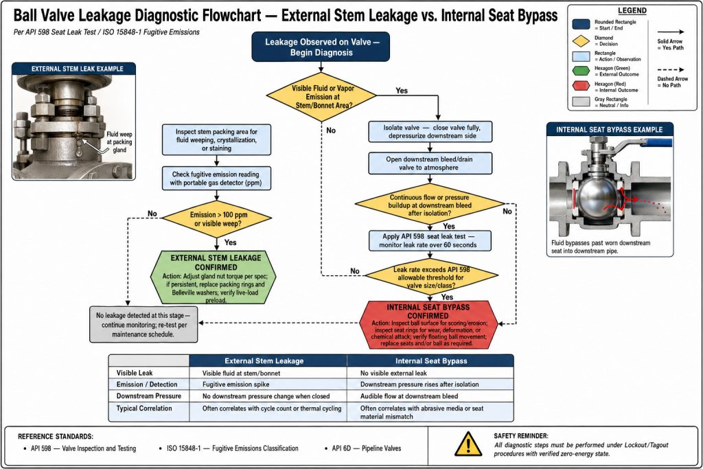
Identifying the specific nature of a leak—whether external past the stem or internal across the valve seats—is the critical first step before initiating any repair. Field technicians must systematically evaluate physical symptoms under operating pressures to isolate the point of failure.
This structured diagnostics phase ensures that maintenance teams do not waste valuable downtime replacing components that are still fully functional.
Stem Packing Leakage Identification
External leakage manifesting around the gland flange or operating lever indicates a compromise in the stem packing or O-ring integrity. This usually occurs when cyclical thermal expansion or high stroke frequency deforms the soft sealing elements over long operating campaigns. Technicians can confirm this visually by searching for product accumulation, salt crusting, or localized corrosion around the valve bonnet.
Internal Seat Bypass Detection
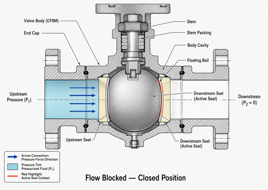
Internal bypass occurs when process media continues to flow downstream even though the valve is fully rotated to the closed position. This is diagnosed using ultrasonic leak detection equipment or downstream temperature differentials on either side of the valve body. If a temperature drop or localized acoustic signature is detected downstream of a closed valve, it indicates that fluid is slipping past the seats.
Steps on How to Fix a Ball Valve Stem Leak
When determining how to fix a ball valve that is leaking from the operating handle, technicians must evaluate whether the packing gland simply needs adjustment or if the sealing rings require replacement. Applying precise torque during this process prevents premature stem galling and ensures an effective seal.
Addressing stem leaks promptly protects the surrounding actuator and prevents fugitive emissions from escaping into the atmosphere.
Adjusting the Packing Gland Nut
Many modern industrial valves feature an adjustable packing gland nut designed to compress the packing rings against the stem and stuffing box. Tightening the gland nut clockwise in small increments—typically one-twelfth to one-sixth of a turn—re-establishes the radial compression required to stop minor external leaks. Care must be taken not to over-tighten, as excessive torque increases operating friction and can cause premature actuator wear.
Replacing Worn Stem Seals
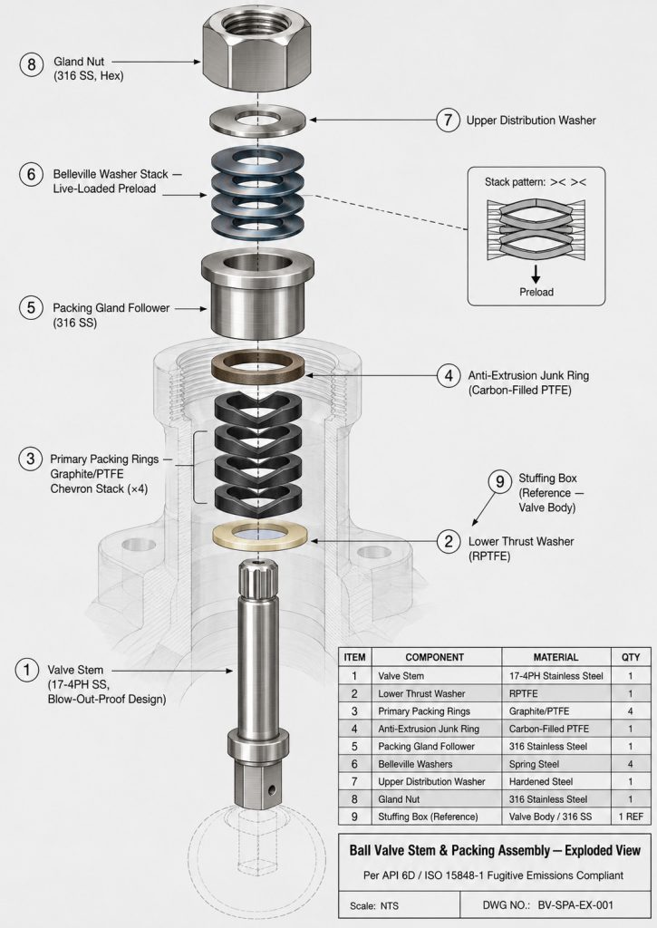
When gland adjustment no longer halts leakage, the packing rings or stem O-rings must be fully replaced. The process requires isolating the line, removing the handle or actuator, backing off the packing nut, and using a specialized packing extractor tool to remove the old seals without scratching the metal stem. New packing rings, typically composed of PTFE, TFM, or graphite for high-temperature service, are then carefully stacked and compressed into place.
Replacing Damaged Seats to Stop Bypass
Stopping internal bypass leakage requires disassembling the valve body and replacing the degraded PTFE or metal seats that fail to maintain a tight seal against the ball surface. This corrective action is essential for maintaining process control and protecting downstream equipment.
Replacing the seats is often combined with a thorough inspection of the ball surface to ensure no abrasive wear has occurred.
Body Disassembly and Ball Removal
For split-body or three-piece flanged ball valves, the body bolts must be loosened and removed to access the internal cavity. Once the body halves are separated, the ball can be rotated to the fully closed position and gently lifted out of the seat pockets. The ball must be immediately inspected for surface scratches, pitting, or abrasive wear that would prevent a tight seal.
Installing New Seat Rings
Old, deformed, or scorched seat rings must be pried out of their body recesses using non-marring brass tools to prevent damaging the stainless steel valve body. The cavity must be thoroughly cleaned of any scale, corrosion, or polymer build-up before the new seats are pressed into place. It is critical to ensure that the seat profiles are properly aligned and that any cavity pressure relief channels face the correct direction.
Restoring Motion to Stuck Actuators

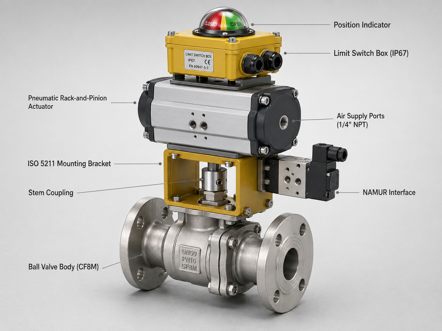
Resolving a stuck or difficult-to-turn ball valve requires clearing internal debris accumulation, lubricating the stem journal, or recalibrating the torque output of the actuator. When automating systems with pneumatic ball valves, ensuring proper torque alignment between the actuator and stem is critical.
A stuck valve can disrupt automated safety loops, making immediate intervention necessary to maintain safe plant operations.
Clearing Debris and Media Build-Up
Process fluids that carry suspended solids, polymers, or highly viscous compounds can cause media to build up in the cavity behind the ball. This build-up increases friction, making manual or automated operation exceptionally difficult. Flushing the valve with a compatible solvent or disassembling the valve to clean the cavity often restores smooth rotation.
Actuator Alignment and Recalibration
Stiffness is frequently caused not by the valve itself, but by mechanical misalignment between the valve stem and the actuator drive shaft. This misalignment creates a side-load on the stem packing, leading to high torque spikes and eventual leakage. Loosening the mounting bracket bolts, cycling the valve to find its natural center, and re-torquing the mounting hardware solves this issue.
Troubleshooting Parameters and Torque
Executing a successful repair relies on adhering to precise torque parameters and selecting sealing materials that match the process system’s pressure and temperature demands. Utilizing the incorrect materials or improper torque settings can lead to catastrophic rapid failure upon system restart. For complex distribution lines utilizing three-way ball valves, verifying port alignment during reassembly is equally critical and knowing how to fix a ball valve according to its design specification prevents future failures.
| Component | Common Issue | Diagnostic Standard | Rectification Strategy | Typical Torque / Material Guide |
|---|---|---|---|---|
| Stem Packing | External Leakage | Bubble test (soap solution) or visual moisture around gland. | Adjust gland nut or replace packing rings. | Tighten to hand-tight plus 1/4 turn, or follow manufacturer torque limits. |
| Valve Seats | Internal Bypass | Acoustic monitoring or downstream thermal tracking. | Disassemble body and install new seat rings. | Select soft (PTFE/RPTFE) or hard (PEEK/Metal) based on media temperature. |
| Body Gasket | Joint Leakage | Visual drop or weeping at body split connection. | Replace spiral-wound gasket or O-ring; re-torque bolts. | Tighten body bolts in star pattern to nominal standard torque. |
| Stem Journal | High Torque / Jamming | Actuator stall or high manual resistance. | Flush valve cavity or realign stem-to-actuator coupling. | Apply compatible silicone or hydrocarbon grease to stem journals. |
Key Takeaway: Always perform a low-pressure hydrostatic test on a repaired valve before reintroducing it to high-pressure service to confirm seat and stem integrity.
Gland Nut Torque Guidelines
Over-tightening the gland nut can deform the packing rings and cause permanent deformation, which ironically leads to more severe leaks later on. Technicians must apply torque incrementally, monitoring the force required to turn the valve. If a torque wrench is available, it should be adjusted to the manufacturer’s specific settings, which typically correspond to the minimum force required to achieve a seal under test pressures.
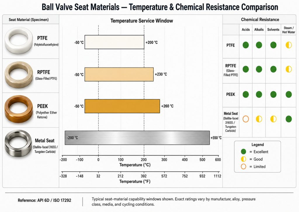
Seat Material Selection Criteria
When replacing seats, matching the material to the system parameters is critical for ensuring longevity. Standard Virgin PTFE is excellent for general chemical compatibility at moderate temperatures, whereas Reinforced PTFE (RPTFE) offers superior wear resistance under higher pressures. For extreme temperatures or abrasive slurry services, advanced materials such as PEEK or metal-to-metal seats must be used.
Safety Protocols for Valve Maintenance
Performing maintenance on any pressurized line requires absolute adherence to Lockout/Tagout (LOTO) and verified dual-isolation depressurization procedures. Failure to secure the system properly can lead to sudden high-pressure releases of hazardous media.
Establishing a double block and bleed system is highly recommended when working on critical process lines.
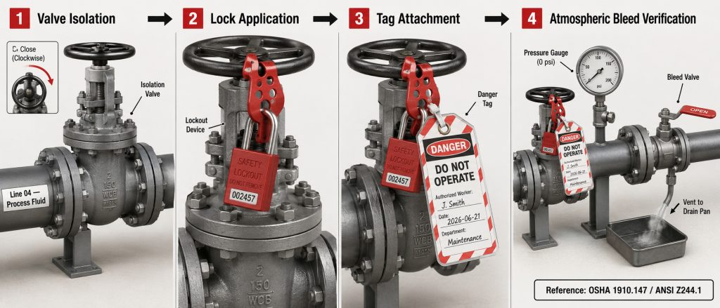
Isolation and Depressurization Steps
- Step 1: Isolate the target valve by closing the nearest upstream and downstream block valves.
- Step 2: Apply personal Lockout/Tagout (LOTO) padlocks and warning tags to all isolation valve actuators.
- Step 3: Open intermediate bleed valves or drain ports to safely discharge trapped pressure from the isolated piping spool.
- Step 4: Verify that the pressure gauge reads zero before loosening any body bolts on the target valve.
Post-Maintenance Testing Procedures
Once the repairs are complete, the valve must be tested before being placed back into regular service. This involves performing a shell test and a seat closure test, ideally using low-pressure air or nitrogen to check for bubbles at the stem and seats. If the valve passes these initial integrity tests, it can be slowly reintroduced to full system pressure while technicians monitor for any signs of thermal or mechanical settling.
Frequently Asked Questions
Is it more cost-effective to learn how to fix a ball valve or replace it?
It depends on the valve’s size and pressure class, with larger or high-pressure valves being much more cost-effective to repair. For small, low-cost utility valves under two inches, the labor cost of disassembly often exceeds the price of a replacement unit. However, for large flanged, high-performance, or exotic alloy ball valves, replacing worn seats and seals can save up to 70% of the cost of buying a new valve, making repair the preferred B2B strategy.
Can a soft-seated ball valve be repaired while still under full system pressure?
Absolutely not, as performing any maintenance on a pressurized valve is an extremely dangerous safety violation. The internal line pressure will violently eject the stem or packing components once the gland nut is loosened, leading to severe injury and uncontrolled fluid release. The line must always be fully isolated, depressurized, and drained before attempting any repairs.
How can you determine if an internal leak is caused by seat wear or ball scratching?
A visual inspection after disassembly is the only definitive way to distinguish between seat degradation and a damaged ball. Seat wear typically presents as uniform thinning, deformation, or tearing of the polymer ring. In contrast, a damaged ball will show distinct linear scratches, pitting, or gouges on its spherical surface, which act as micro-channels for fluid bypass even if brand-new seats are installed.
What are the primary warning signs that a ball valve is beyond repair and must be scrapped?
A valve is beyond repair when there is severe body erosion, cracked metal casings, or deep gouging on the internal sealing surfaces of the body itself. If the valve body’s metal-to-metal joint surfaces or stuffing box walls are corroded or deformed, installing new soft parts will not stop leaks. In these scenarios, complete valve replacement is the only safe and reliable option.
Comprehensive Valve Integrity and Long-Term Performance
Successfully repairing an industrial ball valve relies on utilizing high-quality sealing components, adhering strictly to safety standards, and matching the replacement parts to the specific demands of your process environment. Regular maintenance, including minor packing adjustments and cavity flushes, can significantly prolong the operational life of your valves, ensuring consistent system pressure and preventing costly unscheduled downtime.
For plants and facilities looking to optimize their fluid control infrastructure, Ruito provides engineered-to-order flow solutions designed to withstand high-cycle and highly corrosive applications. To discuss custom seat materials, actuator upgrades, or to procure highly durable valve assemblies for your system, please contact Ruito’s engineering team to receive a tailored technical consultation.