
In heavy industrial facilities, municipal utility networks, and automated process lines, managing fluid flow requires deep knowledge of quarter-turn isolation equipment. Knowing how to open a ball valve properly is a fundamental skill for field operators, maintenance technicians, and piping engineers. While the basic mechanics of rotating a lever may seem straightforward, doing so safely within high-pressure, high-velocity piping networks requires a thorough understanding of fluid dynamics, pressure differentials, and mechanical limits. Missteps during standard valve operation can cause severe downstream hydraulic shocks, unexpected mechanical failures, or seat degradation.
Selecting high-performance flow control equipment from a qualified industrial ball valve manufacturer is the first step toward long-term system integrity. Once installed, these valves must be operated and maintained according to strict engineering standards to prevent downtime and protect downstream instrumentation. This comprehensive technical guide details the mechanical procedures, safety precautions, and troubleshooting steps needed to open manual, geared, and automated ball valves in industrial systems.
1. Visual Position Identification and Internal Flow Dynamics
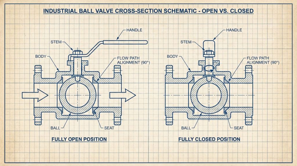
Before adjusting any valve, field personnel must verify its current mechanical position. Because ball valves are quarter-turn isolation devices, their internal design features a spherical ball with a cylindrical bore drilled through the center. This ball rotates on a vertical stem between two resilient or metallic seats. The orientation of the bore relative to the pipeline axis determines whether the valve is open or closed.
Lever and T-Handle Indicators
For standard manual valves, the orientation of the lever or T-handle serves as a visual indicator of the internal flow path:
- Parallel Orientation: When the handle is aligned parallel to the pipeline run, the internal bore matches the flow path, indicating that the valve is open.
- Perpendicular Orientation: When the handle is turned perpendicular (90 degrees) to the pipeline, the solid metal face of the ball faces the incoming media, indicating that the valve is closed.
Cross-Sectional Geometry of Open vs. Closed States
In a fully open position, the internal bore of the ball aligns precisely with the pipe’s inside diameter. If the valve is a full-port design, this alignment creates an unobstructed, straight-through flow path with minimal pressure drop, which helps reduce turbulent flow and localized erosion.
In the fully closed position, the ball rotates exactly 90 degrees, positioning its solid surface against the seats. System pressure presses the ball against the downstream seat, creating a tight, reliable seal.
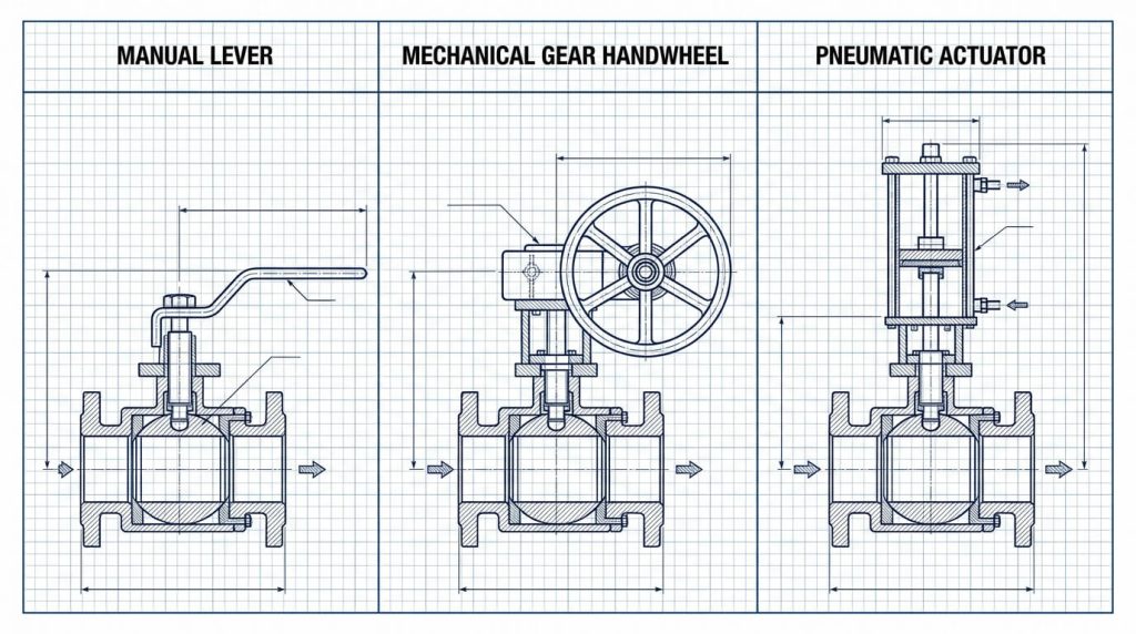
Actuator Visual Beacons and Indicators
On automated or actuated valves where manual levers are absent, operators must rely on physical indicator beacons. These high-visibility mechanical indicators are typically mounted directly to the top of the pneumatic or electric actuator stem:
- A colored indicator or arrow showing “OPEN” (typically green) or “CLOSED” (typically red) confirms the position of the internal ball.
- In digital systems, electronic limit switches transmit real-time valve position signals directly to the control room, providing remote verification.
2. Step-by-Step Protocols for Operating Manual Ball Valves
Operating a manual ball valve involves more than just a quick turn of the lever. In large-diameter or high-pressure systems, opening a valve too quickly can cause sudden pressure waves that stress the piping network. For applications requiring slow, highly controlled throttling, process designs may specify multi-turn equipment like a standard gate valve rather than a quick-opening quarter-turn valve.
Pre-Operation Inspection Checklist
Before attempting to open any manual isolation valve, operators should complete a basic physical inspection:
- Debris and Corrosion Check: Inspect the stem, lever, and travel stops for heavy dirt, scale, or visible corrosion that could hinder rotation.
- Packing Gland Verification: Visually check the stem packing gland for any evidence of process media weeping or leakage.
- Upstream Pressure Readings: Check upstream and downstream pressure gauges to identify any significant differential pressure across the valve.
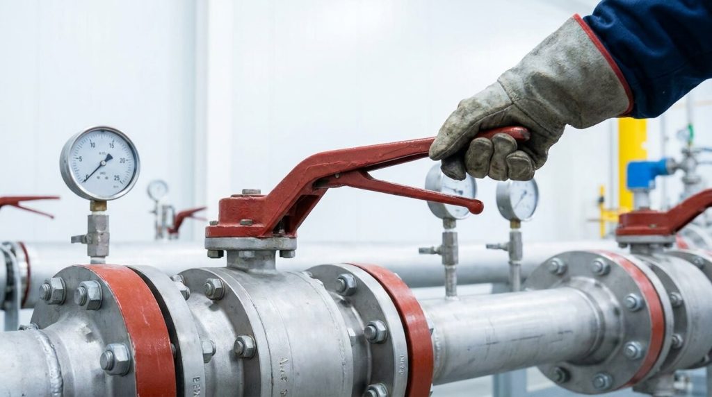
Manual Lever and T-Handle Operation
To open a lever-operated ball valve, use the following procedure:
- Grip Firmly: Place a secure grip on the outer end of the lever to maximize mechanical leverage.
- Rotate Slowly Counter-Clockwise: Turn the handle counter-clockwise in a slow, controlled motion. Avoid sudden, jerking movements that can cause rapid pressure spikes downstream.
- Engage Travel Stops: Continue rotating until the handle contacts the built-in mechanical travel stops on the valve bonnet.
- Verify Alignment: Confirm that the lever is fully parallel to the pipeline axis, indicating that the internal port is completely open.
Gear Operator Handwheel Mechanics
For larger valve sizes, manually turning a standard lever may require more physical effort than is safe for an operator. In these installations, mechanical gear operators are used to reduce the required manual input torque:
- Check the Indicator: Locate the position indicator pointer on top of the gearbox housing.
- Rotate Counter-Clockwise: Turn the handwheel counter-clockwise. Gearbox operators require multiple full turns of the handwheel to complete the 90-degree internal rotation.
- Avoid Over-Tightening: Rotate the handwheel until the indicator points to “OPEN.” Stop turning as soon as you feel mechanical resistance; forcing the wheel past its limit can damage the internal gearing.
3. Operating Actuated and Automated Ball Valves
In modern processing plants, automated actuators are used to manage valves remotely, handle high-torque requirements, and enable automated safety shutdowns. These systems use compressed air, electricity, or hydraulic fluid to turn the valve stem.
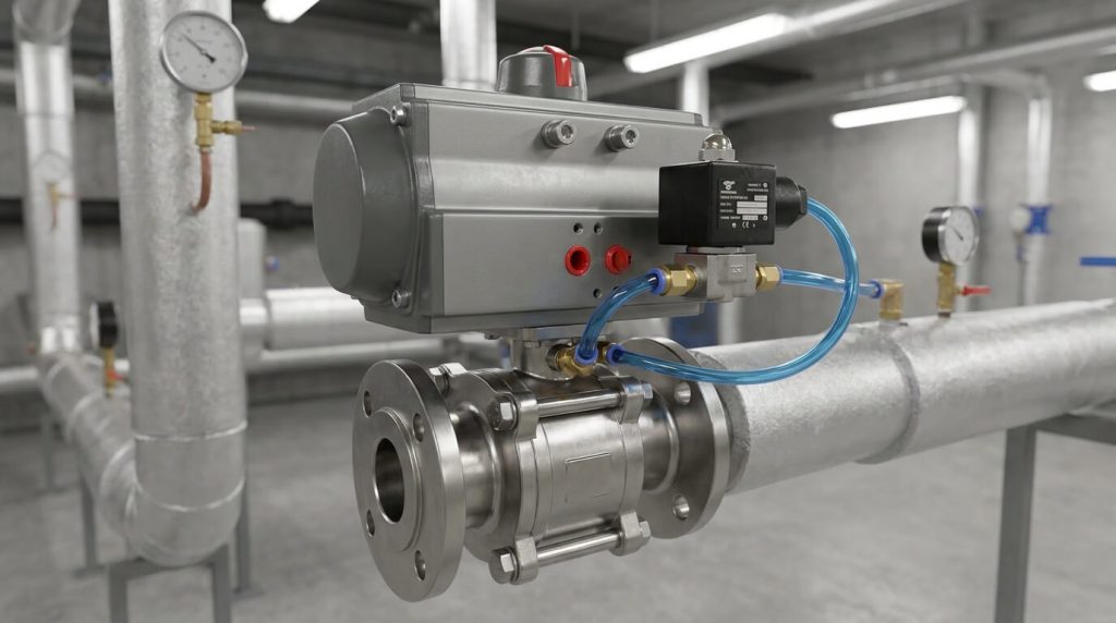
Pneumatic Rack-and-Pinion Actuators
Pneumatic actuators are widely used for rapid, reliable quarter-turn operation. They typically use a rack-and-pinion design powered by clean, dry instrument air:
- Double-Acting Actuators: These units use pressurized air to drive pistons in both directions. To open the valve, an electrical signal energizes an attached solenoid valve, routing air to the opening chamber and venting the closing chamber.
- Spring-Return (Fail-Safe) Actuators: These configurations use air pressure to compress internal heavy-duty springs during the opening stroke. If control air pressure is lost, the compressed springs expand, automatically returning the valve to its designated fail-safe position (either fully open or fully closed, depending on safety design).
Electric and Hydraulic Actuation Control Loops
For high-precision installations or locations without access to compressed air, electric or hydraulic actuators are used:
- Electric Actuators: These systems use electric motors combined with high-ratio gearboxes to turn the valve stem. Internal limit switches shut off power once the valve reaches its fully open or fully closed position, protecting the motor from damage.
- Hydraulic Actuators: These actuators use pressurized hydraulic fluid to deliver the high torque required for very large valves in high-pressure installations. They provide smooth, consistent movement and can handle significant process loads.
4. Safety Protocols: Preventing Water Hammer and Managing Differentials
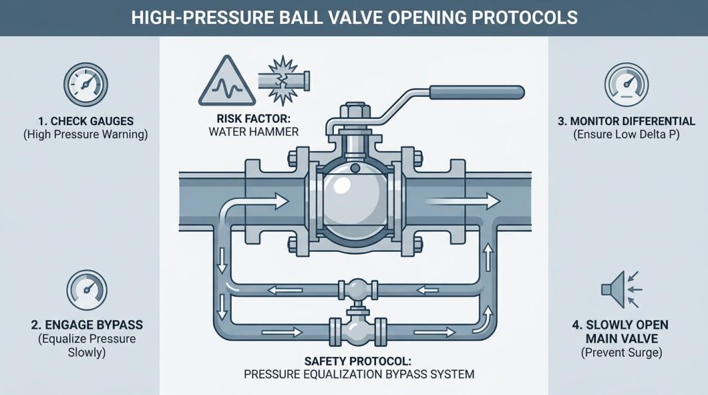
Operating high-pressure process systems requires careful safety protocols to prevent pipeline damage and protect plant personnel. Rapidly opening a valve under high differential pressure can cause downstream failures due to sudden fluid velocity waves. In industrial facilities like chemical processing lines, operators must wear chemical-resistant safety gear and follow Lockout/Tagout (LOTO) procedures before making any process adjustments.
Preventing Water Hammer Shock
Water hammer is a high-pressure surge that occurs when a fluid in motion is forced to change direction or stop suddenly. When a ball valve in a liquid system is opened too quickly, it can cause a rapid rush of fluid that impacts downstream components:
- Control Opening Speed: Always open isolation valves slowly, especially in liquid lines.
- Allow Pressure to Equalize: Opening the valve gradually lets downstream pressure build incrementally, dissipating kinetic energy safely and preserving pipeline integrity.
Managing High-Pressure Differentials
When a valve remains closed under high pressure, a substantial pressure differential ($\Delta P$) builds across the ball, pushing it tightly against the downstream seat. This increases the friction between the ball and the seat, requiring much higher torque to open the valve:
- High Operational Torque: Attempting to force a valve open under a high pressure differential can damage the soft seats or even shear the valve stem.
- Utilize Bypass Equalization Loops: Installing a small bypass line with a secondary valve allows operators to slowly route fluid around the closed main valve. Once downstream pressure equalizes with upstream pressure, the main valve can be opened with minimal resistance.
5. Valve Selection Criteria and Operating Torque Analysis
Choosing the right valve and operating mechanism depends on pipeline diameter, operating pressure, and the speed required for process control. While manual levers are cost-effective for smaller lines, large-diameter systems require mechanical gear assist or automation to overcome fluid forces. For critical municipal networks, such as water and wastewater treatment facilities, choosing the correct configuration ensures long-term operational safety and compliance with environmental regulations.
In some application scenarios, a multi-turn design like a butterfly valve or a specialized globe valve may be considered alongside or instead of a ball valve, depending on space limitations, pressure ratings, and flow-throttling requirements.
Technical Performance and Mechanism Comparison
The table below outlines key technical characteristics, pressure considerations, and size guidelines for various ball valve configurations.
| Operating Mechanism | Torque Capacity Range | Typical Opening Speed | Primary Safety Advantage | Compatible Valve Sizes | Design Standards |
|---|---|---|---|---|---|
| Manual Lever | Low (typically limited to $<150 \text{ Nm}$) | Very Fast (approx. $1 – 2 \text{ seconds}$) | Direct, tactile feel for mechanical obstruction | DN15 to DN100 (subject to pressure limits) | ASME B16.34, API 608 |
| Gear Operator | Moderate to High ($150 \text{ to } >5,000 \text{ Nm}$) | Slow (requires multiple handwheel turns) | Minimal risk of water hammer from rapid opening | DN150 to DN300 (depending on torque requirements) | ASME B16.34, API 6D |
| Pneumatic Actuator | High ($50 \text{ to } >10,000 \text{ Nm}$) | Fast ($<1 \text{ to } 5 \text{ seconds}$, adjustable) | Fail-safe spring return options for emergency shutdowns | DN50 to DN600+ (highly adaptable) | ISO 5211, EN 15714-3 |
| Electric Actuator | Very High ($30 \text{ to } >20,000 \text{ Nm}$) | Slow to Moderate ($10 \text{ to } 60 \text{ seconds}$) | Adjustable electronic torque limits prevent stem damage | DN50 to DN900+ (ideal for remote control) | ISO 5211, EN 15714-2 |
Note: Torque values and pressure classes are typical industry estimates and may vary based on specific seat materials, media types, and manufacturer designs.
6. Troubleshooting and Maintaining Stuck or Seized Ball Valves
Over time, exposure to harsh media, temperature swings, or lack of regular use can cause isolation valves to bind or seize. If a valve is stuck, applying excessive force is not the solution and can easily damage the stem or internal components. Operators should follow a systematic process to identify the cause of the resistance before attempting further rotation.
Mitigating Thermal Binding and Particulate Scale Buildup
In high-temperature applications, thermal expansion can cause the metal ball to expand slightly faster than the surrounding body, resulting in binding. Additionally, mineral scale or particulate buildup can wedge itself between the ball and the resilient seats:
- Temperature Equalization: Allow high-temperature systems to cool slightly to relieve thermal binding before attempting to operate the valve.
- Flushing the Line: If particulate scale is the cause, flushing the pipeline with clean fluid or a compatible solvent can help dislodge debris trapped around the seats.
Stem Packing Adjustment and Lubrication Guidelines
Stiff stem packing is a common cause of high operating torque and manual handle stiffness:
- Apply Lubrication: Apply a compatible penetrating lubricant directly to the stem gland area to help free up seized threads.
- Adjust the Packing Nut: If the valve remains stiff, the packing nut may need a slight adjustment to relieve excessive compressive force. This adjustment must be done carefully, keeping in mind system pressure limits and local safety guidelines to prevent leakage.
- Follow a Routine Cycling Schedule: Regularly exercising idle valves helps prevent media stagnation and mineral scale buildup, keeping the valve operating smoothly.
Frequently Asked Questions
Can a standard manual ball valve be opened partially to regulate flow?
No, standard ball valves are generally not recommended for throttling or flow regulation.
Operating them in a semi-open state exposes the soft elastomeric or thermoplastic seats to continuous, high-velocity fluid flow. This can lead to rapid seat erosion, localized turbulence, and physical wear, which will eventually compromise the valve’s ability to provide a tight, bubble-tight shutoff.
Why does an idle industrial ball valve become difficult to open over time?
Idle valves often experience increased operating torque due to mineral scale buildup, chemical corrosion, or media stagnation.
When a valve remains in one position for long periods, particulates in the process fluid can settle into the valve cavity and around the seats, increasing friction. This scale buildup increases the force required to turn the ball stem, sometimes causing the valve to seize if it is not cycled regularly.
What are the primary safety risks of opening a ball valve too rapidly?
The main risk is the generation of water hammer or rapid downstream pressure shocks.
Opening a quarter-turn valve too quickly allows a sudden surge of high-velocity fluid to enter empty downstream piping. When this fluid hits bends, closed valves, or air pockets, it can generate massive pressure spikes that can damage piping joints, blow out gaskets, or rupture instrumentation.
How does a double-acting pneumatic actuator open a ball valve compared to a spring-return model?
A double-acting actuator requires pressurized air for both the opening and closing strokes, whereas a spring-return model uses air for one stroke and mechanical springs for the other.
In a double-acting unit, compressed air is actively routed to one side of the internal pistons to open the valve and to the opposite side to close it. A spring-return (or “fail-safe”) actuator uses compressed air to compress heavy-duty internal springs during the opening stroke; if air pressure or control power is lost, the springs automatically expand to return the valve to its safe position.
Conclusion
Safe, reliable flow control depends on choosing the right valve design, conducting regular inspections, and using proper operating techniques. Understanding the differences between manual, geared, and actuated valve configurations allows operators to prevent pipeline shocks and extend seat life.
Selecting the proper valve specification is critical to system safety and uptime. RUITO’s engineering team has extensive experience in manufacturing high-quality, standard-compliant industrial valves. Contact our industrial valve experts today to request full CAD drawings, standard-compliant datasheets, or a detailed custom quote for your pipeline project.
Adhering to recognized standards, such as ASME B16.34 for pressure-temperature ratings and API 6D for pipeline specifications, is essential for high-performance fluid control. When selecting materials like ASTM A216 WCB cast carbon steel or ASTM A351 CF8M stainless steel, engineers must match the material’s properties with the temperature, pressure, and chemical characteristics of the process fluid. Proper valve commissioning, combined with regular training on quarter-turn valve operation, helps ensure that field technicians handle equipment safely and prevent premature mechanical failures.