A ball valve trunnion design anchors the ball and moves the seats to seal, while a floating design uses line pressure to press a slightly movable ball against the downstream seat. When a pipeline package moves toward a larger bore, a higher differential pressure, automated shutdown duty, or cavity-bleed requirements, choosing by valve size alone can produce excessive operating torque, an unsuitable relief path, or the wrong isolation arrangement. This guide compares the two industrial ball valve designs by sealing mechanics, torque, cavity behavior, standards, cost, and service conditions so engineers and procurement teams can specify the design that fits the duty.
How the Ball Valve Trunnion Design Works
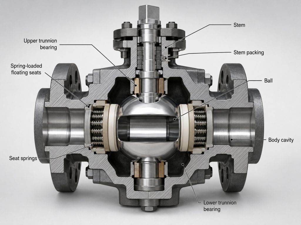
The ball valve trunnion arrangement restrains the ball with upper and lower supports, so the seats provide the controlled movement needed for sealing. Springs establish initial seat contact at low differential pressure, while line pressure can add piston force behind the upstream seat; the exact response depends on whether the manufacturer uses single-piston-effect, double-piston-effect, or another qualified seat design.
Supported Ball and Moving Seats
The supports carry much of the pressure load that would otherwise push a floating ball into the downstream seat. This can make operating torque more predictable as bore and differential pressure increase, but it does not remove friction from seats, bearings, stem packing, or deposits in the cavity.
The term “trunnion” describes the ball support, not a complete performance rating. Body construction, seat geometry, seal materials, bore, end connections, and the actuator still have to be evaluated as one assembly.
Low-Pressure and Pressure-Assisted Sealing
Seat springs help maintain contact when line pressure is low. As differential pressure develops, the applicable seat geometry converts pressure into additional sealing force; too little contact can permit leakage, while excessive contact raises torque and wear.
How a Floating Ball Valve Seals
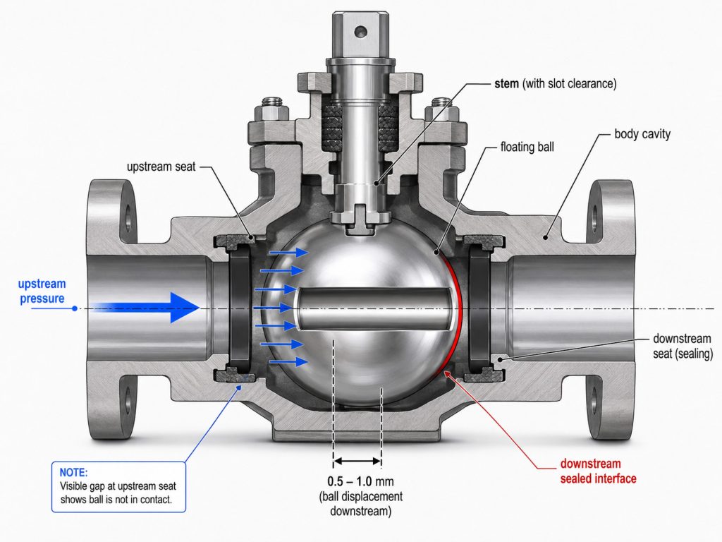
A floating ball valve seals mainly by allowing upstream pressure to load the ball against the downstream seat. The actual displacement is small, but the resulting seat force can rise substantially with differential pressure and ball projected area.
Body-Held Seats and Downstream Sealing
In a conventional floating design, both seats are retained by the body and the ball is not supported by a lower trunnion. Initial seat preload supports low-pressure shutoff, while pressure-assisted loading strengthens contact on the downstream side.
This architecture often means fewer components, a compact envelope, and lower initial cost. Downstream-seat and actuator loads may rise with size, pressure, friction, or long static periods.
What “Floating” Does Not Mean
The ball does not drift visibly through the body cavity during normal operation. “Floating” refers to the small pressure-driven movement that develops sealing contact, not an uncontrolled or loose component.
For a broader explanation of the quarter-turn mechanism, internal parts, and bore options, RUITO’s guide to how a ball valve works provides useful context.
Trunnion and Floating Valve Differences That Matter
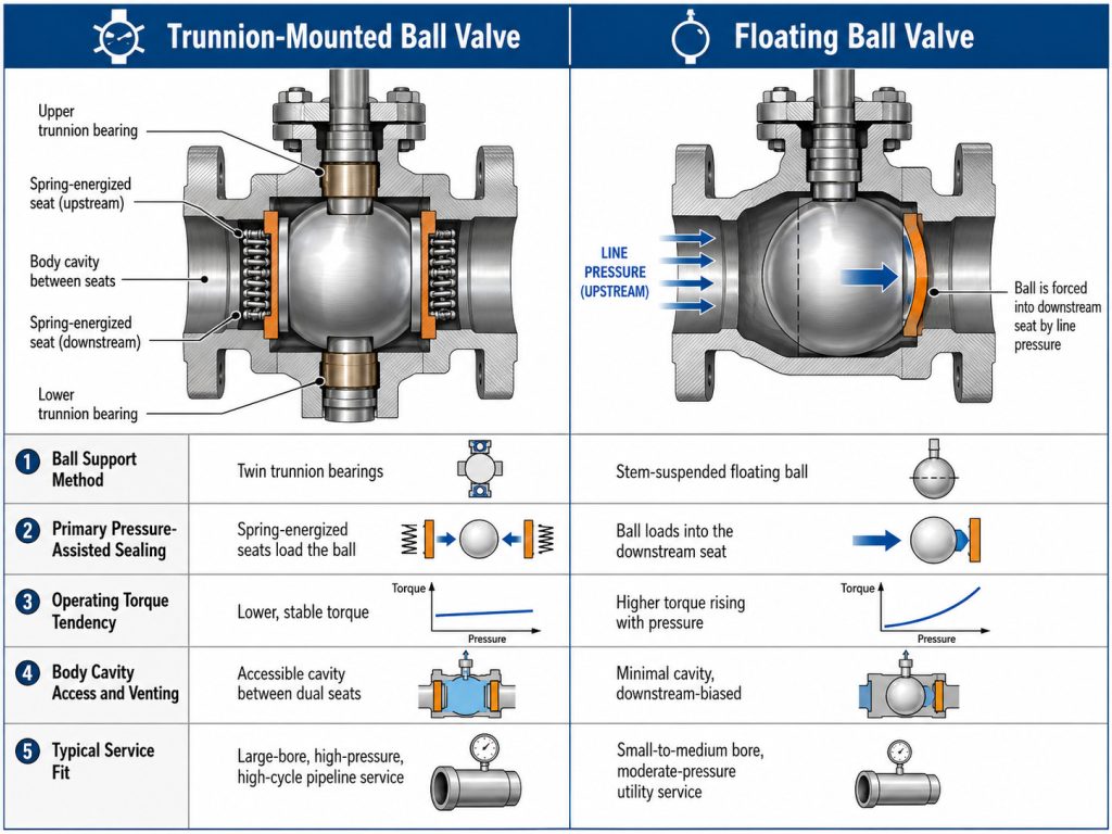
The decisive difference is the pressure-load path: a trunnion valve transfers load through ball supports and moving seats, whereas a floating valve transfers more load through the ball into the downstream seat. The following table turns that mechanical distinction into project decisions.
| Decision factor | Trunnion-mounted design | Floating design | Project implication |
|---|---|---|---|
| Ball support | Ball is restrained by trunnion supports | Ball can move slightly between body-held seats | Changes seat loading and torque behavior |
| Primary pressure-assisted seal | Commonly the upstream seat, depending on seat design | Commonly the downstream seat | Confirm sealing direction with the valve drawing |
| Torque tendency | Often more manageable as pressure area grows | Can rise sharply as pressure forces the ball into the seat | Size the actuator from validated torque data |
| Cavity access | Commonly accommodates a body bleed and defined relief strategy | Conventional designs generally keep the cavity connected to line pressure | Do not infer isolation capability from external appearance |
| Seat arrangements | Can use single- or double-piston-effect seats | Usually uses fixed seat carriers with ball movement | Specify required failure and relief behavior |
| Construction and maintenance | More components, bearings, springs, and seals | Fewer components and simpler disassembly | Compare lifecycle work, not purchase price alone |
| Typical fit | Large-bore, high-differential-pressure, automated, or cavity-managed duty | Compact process or utility isolation where cavity verification is not required | Treat these as tendencies, not size cutoffs |
| Standard scope | Design can fall within pipeline-valve standards | Design can also fall within pipeline-valve standards | ISO 14313:2025 applies to ball valves in ASME Classes 150, 300, 600, 900, 1500, and 2500; class alone does not choose the support design |
The table shows why “trunnion equals high pressure” is incomplete. Bore, differential pressure, seats, actuator margin, cavity requirements, and maintenance access can change the result.
Pressure, Bore, Torque, and Actuation
Choose the support design and actuator together because pressure load, bore area, seat friction, and operating condition determine the required torque. A trunnion arrangement often limits pressure-driven ball movement, while a floating arrangement may remain economical and practical when the resulting seat load is manageable.
Differential Pressure Is More Useful Than Line Pressure Alone
Actuator sizing should consider the maximum differential pressure during opening or closing, not merely normal operating pressure. Break, run, closing, and emergency cases can impose different demands.
Ask the supplier for torque values tied to the offered size, pressure class, seat material, temperature, medium, and differential-pressure direction. If an automated assembly stalls, the diagnostic path should separate valve friction from actuator supply and coupling problems; RUITO’s discussion of a ball valve stuck on an automated actuator outlines those checks.
Full Bore, Reduced Bore, and Pipeline Function
A full-bore requirement may be driven by pigging, cleaning, pressure-loss limits, or process continuity rather than by the trunnion label itself. Reduced-bore valves can lower envelope and cost in suitable services, but the project must evaluate velocity, pressure drop, erosion, and pig passage.
Face-to-face interchangeability is a separate specification issue. ASME B16.10-2022 covers face-to-face and end-to-end dimensions to support interchangeability for a given valve material, type, size, rating class, and end connection.
Seats, Cavity Pressure, and Isolation Functions
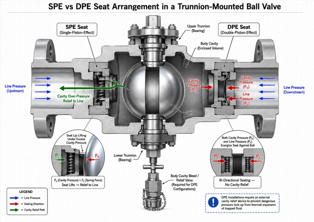
Seat design and cavity-pressure management matter more than the trunnion label when an isolation philosophy requires bleed verification or thermal relief. A supported ball enables several seat arrangements, but each arrangement produces a different response to line pressure and trapped cavity pressure.
Single- and Double-Piston-Effect Seats
A single-piston-effect seat can be arranged to seal from line pressure and release excess cavity pressure when the cavity-to-line differential overcomes the seat load. A double-piston-effect seat can add sealing force from either side of the seat, which can improve isolation redundancy but may require a separate cavity-relief provision.
These descriptions are functional, not universal. Confirm the relief direction and upstream-downstream seat combination from the section drawing and project specification.
DBB Is a Specified Function, Not a Nickname
Do not assume every trunnion valve provides double block and bleed, and do not treat DBB and double isolation and bleed as interchangeable. The purchase specification should identify the governing definition, pressure direction, seat arrangement, body bleed connection, test sequence, and acceptable leakage criterion.
Seat material also changes friction, temperature capability, chemical compatibility, and debris tolerance. RUITO’s article on ball valve PTFE seat behavior explains creep, thermal cycling, wear, and filled-composite considerations without turning one material into a default for every service.
Where Each Design Usually Fits
Trunnion-mounted valves are usually favored when the project needs controlled torque at a large pressure area, defined cavity management, frequent automation, or a documented isolation function. Floating valves are often a strong fit where compactness, simpler maintenance, and lower acquisition cost matter and the pressure-induced seat load remains acceptable.
Typical Trunnion Applications
Transmission lines, compressor or pumping stations, emergency shutdown points, and piggable headers often justify a supported ball and engineered seat system. In oil and gas flow-control applications, the decision should still be tied to the medium, pressure-temperature envelope, solids, corrosion allowance, operating frequency, shutdown time, and governing pipeline specification.
Trunnion construction can suit abrasive service when paired with appropriate hard-facing, seats, coatings, and debris management. Those features are optional, not automatic.
Typical Floating Applications
Floating valves commonly serve process skids, utilities, instrument connections, and general isolation duties where the bore and differential pressure permit acceptable torque. They can be manual or automated and can offer bidirectional shutoff when the manufacturer rates the valve for that duty.
Avoid using an arbitrary size threshold. A demanding small valve may justify trunnion support, while a larger floating valve may remain suitable under a specific manufacturer’s rating and service conditions.
Standards and Tests to Put on the Datasheet
The datasheet should name the applicable design, dimensional, testing, and emissions requirements rather than asking only for a “standard ball valve.” That wording keeps the valve support design connected to measurable acceptance criteria.
Design and Dimensional References
The current ISO 14313:2025 pipeline-valve standard is Edition 3, published in June 2025; it defines requirements for design, manufacturing, materials, welding, quality control, assembly, testing, documentation, and process control, and supplements API 6D, 25th Edition from 2021. API’s own 25th Edition announcement confirms that the specification defines manufacturing requirements for valves used internationally.
For pressure-temperature ratings and construction requirements, ASME B16.34-2025 covers dimensions, tolerances, materials, nondestructive examination, testing, and marking for specified flanged, threaded, welding-end, wafer, and flangeless valves. The purchase order should state the project-required edition rather than silently substituting the latest website listing.
Pressure Testing and External Leakage
ISO 5208:2015, Edition 4, addresses examinations and tests for pressure-boundary integrity, closure tightness, and structural adequacy of the closure mechanism. It also states that a product standard takes precedence where its requirements differ, so the datasheet should identify both the product standard and the agreed leakage acceptance.
For volatile air pollutants or hazardous fluids, ISO 15848-1:2015, Edition 2 with a 2017 amendment, provides type-testing and classification procedures for external leakage from stem or shaft seals and body joints. Fire testing, antistatic continuity, low-temperature qualification, and material traceability should be added only when the service or project specification requires them.
A Practical Selection Workflow
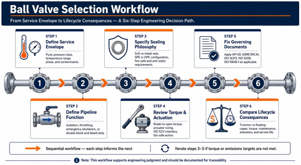
Select the design by resolving the service, isolation function, seat behavior, torque, standards, and lifecycle constraints in that order. A familiar pressure class is not a substitute for engineering fit.
- Define the service envelope. Record the medium, composition, solids, design and operating pressure, design and operating temperature, maximum differential pressure, flow direction, and cycling frequency.
- Define the pipeline function. State whether the valve is for routine isolation, emergency shutdown, pigging, throttling, venting, or verified cavity bleed. Ball valves intended primarily for isolation should not be assigned modulating duty without an appropriate control design.
- Specify the sealing philosophy. Identify soft or metal seats, chemical compatibility, required shutoff direction, cavity-relief path, and any DBB or DIB definition that governs acceptance.
- Review torque and actuation. Require configuration-specific torque data, actuator sizing assumptions, supply conditions, operating time, fail action, mounting interface, and environmental protection.
- Fix the governing documents. List the required editions of the design, pressure-temperature, dimensional, testing, emissions, fire, and project standards, plus the required documentation.
- Compare lifecycle consequences. Evaluate access for packing adjustment, seat or seal replacement, cavity draining, spare parts, actuator removal, inspection, and safe depressurization alongside purchase cost.
Key Takeaway: Choose a ball valve trunnion design when its supported ball, seat architecture, and cavity-management options solve a defined project requirement. Choose a floating design when its simpler load path meets the same pressure, torque, isolation, and maintenance requirements with less complexity.
Conclusion
The correct choice is not “trunnion for every difficult service” or “floating for every smaller line.” It is the design whose pressure-load path, seats, cavity behavior, torque, materials, and qualification requirements match the actual duty.
RUITO can review service conditions, drawings, bore and end connections, seat options, actuation inputs, and test standards before configuration is finalized. RUITO’s practical position is that dependable valve selection begins with transparent engineering assumptions—especially seat behavior, cavity relief, and actuator margin—rather than a design label alone. To compare a proposed trunnion and floating valve, share your operating data and specification requirements with RUITO so unresolved assumptions can be identified before selection.
FAQ
Is a trunnion ball valve automatically better at high pressure?
No. Pressure class alone does not determine the better design. Bore, maximum differential pressure, seat load, torque, cavity strategy, materials, operating frequency, and the manufacturer’s validated rating must be reviewed together.
Can a floating ball valve provide bidirectional shutoff?
Yes, many floating valves are designed for bidirectional shutoff. Confirm the rated direction and test basis on the valve datasheet, and do not confuse bidirectional shutoff with a verified body-cavity bleed function.
Does every trunnion valve provide double block and bleed?
No. A trunnion support makes DBB-oriented seat and cavity arrangements possible, but the required function depends on seat piston effects, pressure direction, bleed provision, governing definition, and successful acceptance testing.
Which design normally costs more?
Trunnion construction generally has a higher initial cost because it adds supports, bearings, springs, seals, and machining steps. Lifecycle cost can reverse the comparison when torque, actuator size, downtime, cavity diagnostics, or maintenance access materially affect the service.
What information should a supplier receive before selection?
Provide the medium, pressure-temperature envelope, maximum differential pressure, size and bore, end connections, materials, shutoff direction, seat and cavity requirements, operating frequency, actuator conditions, applicable standards, and documentation needs. These inputs allow the supplier to evaluate a specific configuration instead of relying on a generic valve-type recommendation.