Knowing how to repair a ball valve starts with a disciplined decision: make the valve safe, diagnose the leak path, then repair only the parts the valve design allows you to service. In plant maintenance, the typical problem is a stem seep, a closed valve that still passes flow, or a valve that becomes hard to operate while the line is needed back in service.
A quick strip-down may feel efficient, but it can waste time if the valve body, ball surface, end connection, or application conditions are already beyond a practical repair. If the valve is misapplied or no longer matches the duty, the better discussion may shift from soft-part repair to a correctly specified industrial ball valve for the service.
Start With Repairability, Not the Tool Bag
A ball valve is repairable only when its body construction, parts availability, and service condition allow safe disassembly and reliable resealing. Before removing bolts or handles, confirm the valve type, size, pressure class, seat material, connection style, and whether the valve was designed for field maintenance.
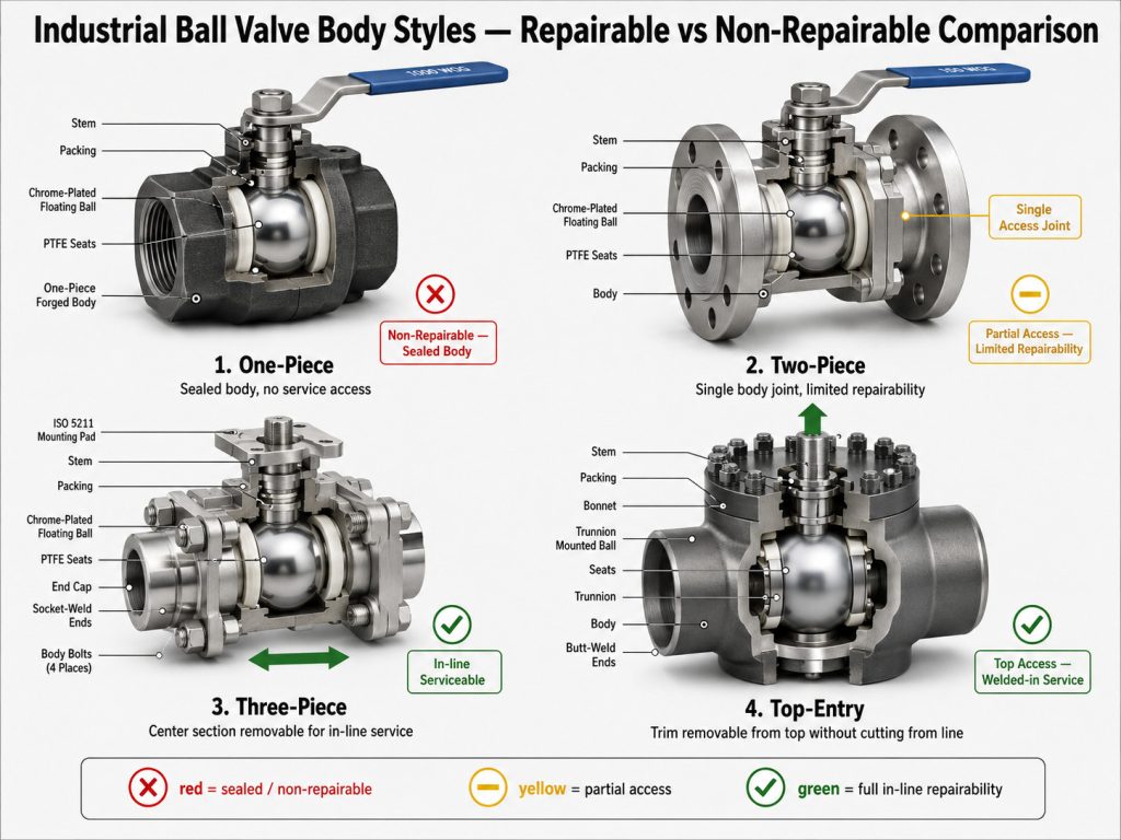
One-piece and sealed bodies
One-piece, crimped, or sealed small valves are often poor repair candidates because the internals are difficult to access without damaging the body or threads. If the valve is low-cost, small bore, or installed in a non-critical utility line, replacement may be more practical than chasing a temporary seal.
Welded-body valves require extra caution. Some welded or fully welded designs are intended for long service life, but not casual field disassembly; repair should follow the manufacturer’s maintenance instructions and the project specification.
Two-piece, three-piece, and top-entry bodies
Two-piece valves may be serviceable, but they usually need removal from the pipeline. Three-piece designs are often easier to maintain because the center section can be accessed after the body bolts are released, provided the line is isolated and the ends remain properly supported.
Top-entry ball valves are designed so internals can be reached from above. That can reduce pipe disturbance, but it does not remove the need for pressure isolation, compatible parts, and post-repair testing.
Diagnose the Leak Before Opening the Valve
The repair path depends on where the valve is failing, not just on the fact that it leaks. A stem leak, body joint leak, seat leak, and actuator-related movement problem each point to different parts and different risks.
A useful first check is to understand how the stem, ball port, and seats interact during opening and closing; the mechanics behind how a ball valve works in industrial piping explain why handle position, ball alignment, and seat loading matter during diagnosis.
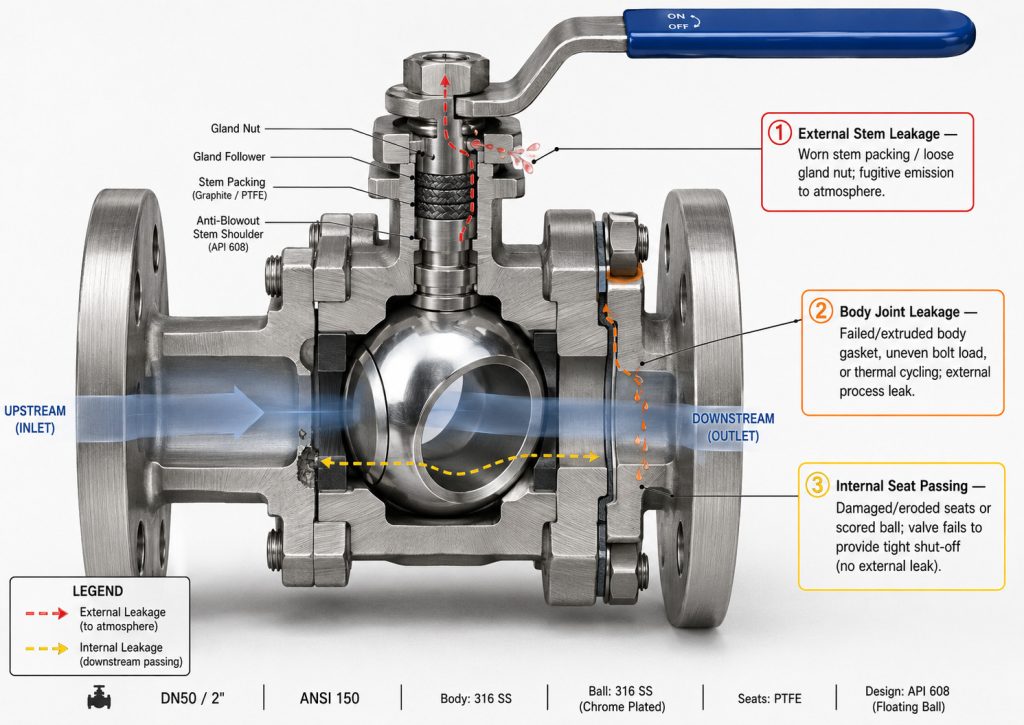
Stem, body, and seat leakage
A stem leak appears around the handle, gland, or packing area. It is usually linked to worn packing, damaged O-rings, stem scoring, over-tightening, or thermal cycling.
A body joint leak appears between bolted body sections or threaded end pieces. A closed valve that still allows downstream flow is usually a seat, ball surface, debris, or alignment problem rather than a stem packing problem.
Hard operation and actuator-related faults
A valve that is hard to turn may have debris in the cavity, damaged seats, corrosion, excessive packing compression, or an actuator that is misaligned or undersized for the service torque. If automation is involved, diagnose the actuator and mounting kit as part of the same failure path, because a ball valve stuck on an automated actuator may not be a body problem.
Forcing the handle is a poor test. It can damage the stem, deform seats, or create a new leak that was not part of the original fault.
Make the Valve Safe to Work On
A ball valve repair should begin with energy control, pressure release, and media control. Even a small valve can retain trapped fluid in the body cavity, and industrial systems may include thermal, chemical, hydraulic, pneumatic, or mechanical stored energy.
In U.S. general industry, OSHA’s 29 CFR 1910.147 lockout/tagout standard covers servicing and maintenance where unexpected energization, startup, or stored-energy release could injure employees; it also identifies a line valve as an energy-isolating device. Local regulations and site procedures may add further requirements.
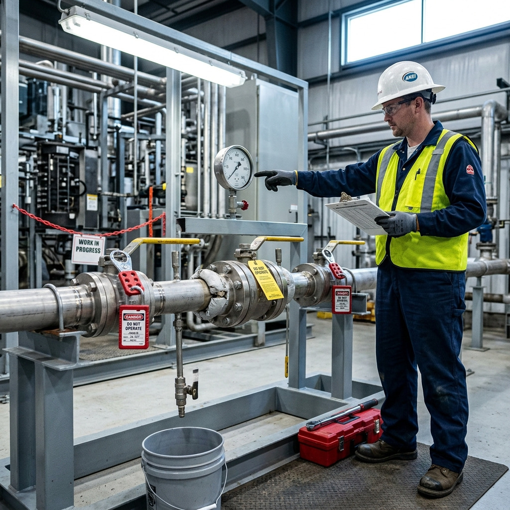
Isolation and stored pressure
Close upstream and downstream isolation points according to the site procedure, lock and tag them where required, then drain and vent the section. Cycle the ball valve only when the system is confirmed isolated and the action is safe for the media and process.
Do not assume a zero line gauge proves the valve body is empty. Some cavities can hold liquid, gas, or residue after the surrounding pipe has been drained.
Cleaning, draining, and media controls
Confirm what the valve has handled before opening it. Steam, hydrocarbons, acids, solvents, slurries, oxygen service, and high-temperature fluids each require different cleaning and handling controls.
Use compatible flushing or cleaning methods only. A solvent that attacks the seat, packing, or elastomer can turn a repair into a repeat failure.
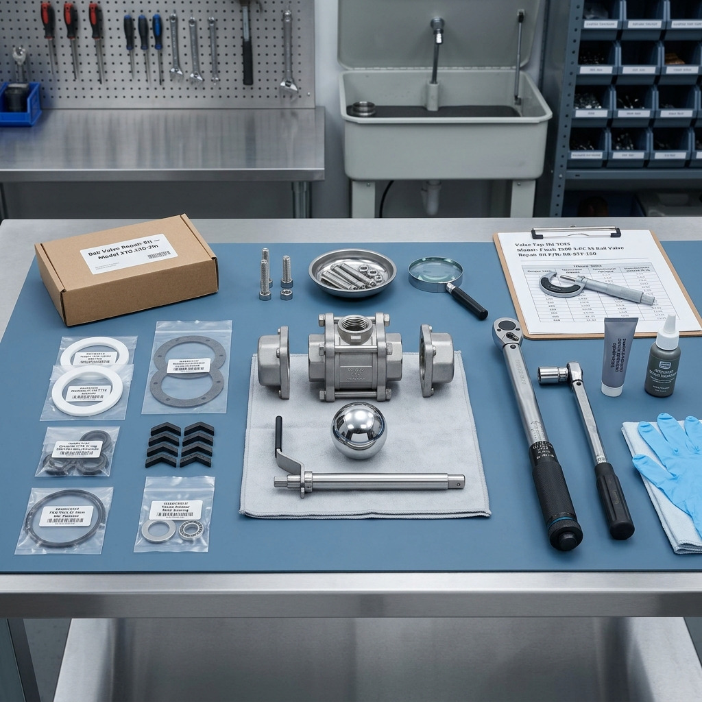
Prepare Parts That Match the Valve and Service
A good repair kit is not just “the same size.” It must match the valve model, body design, seat geometry, stem packing arrangement, material compatibility, and operating conditions.
Generic seats or gaskets can appear to fit but fail under pressure, temperature, cycling, or chemical exposure. The same service factors that shorten the life of a ball valve PTFE seat can make a quick repair fail again if the replacement material is not suitable.
Repair kit and material checks
Confirm the seat material, body seal material, stem packing, thrust washer, and any antistatic or fire-safe design features before ordering parts. Do not replace a soft seat with a different material just because it is available.
For chemical or high-temperature service, check compatibility against the project specification or manufacturer’s published limits. A seal material that works in clean water may not suit solvents, steam, abrasive slurry, or frequent cycling.
Tools and documents
Prepare clean tools, soft-jaw clamping, compatible lubricant, lint-free cleaning materials, and the correct torque information from the valve documentation. Avoid gripping sealing surfaces, polished ball surfaces, or stem sealing areas with hard tools.
Take photos during disassembly. They help confirm handle position, stop plate orientation, packing order, and seat direction during reassembly.
How to repair a ball valve step by step
The safest way to learn how to repair a ball valve is to work from the least invasive action to full soft-part replacement. If a light stem leak can be corrected by controlled packing adjustment, avoid opening the pressure boundary unnecessarily; if the valve passes internally, plan for seat and ball inspection.
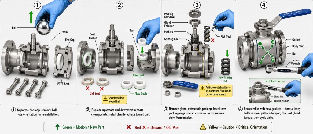
Adjust before you disassemble
For minor stem seepage, tighten the packing gland in small controlled increments only if the valve documentation allows adjustment. The goal is to stop the leak while maintaining smooth operation, not to crush the packing until the handle becomes stiff.
For packing-only symptoms, the adjustment window is narrower than many teams expect, especially on a leaking ball valve stem packing case where over-tightening can raise operating torque.
Replace soft parts cleanly
After isolation and depressurization, remove the handle, gland components, body fasteners, end cap, seats, ball, stem seals, and body gasket according to the valve design. Keep the ball protected; scratches, dents, or embedded particles on the sealing surface can cause internal passing after reassembly.
Install new seats, stem packing, thrust washers, and body seals from a compatible kit. Reusing old soft parts is usually false economy because they have already taken a compression set, chemical exposure, or wear pattern.
Reassemble without distorting the body
Clean the body recesses and sealing faces before reassembly. Tighten body bolts gradually in a cross pattern where applicable, using the manufacturer’s torque values instead of guesswork.
Cycle the valve several times after assembly. Movement should be smooth and consistent; sudden stiffness can indicate over-compressed packing, misaligned seats, debris, or actuator coupling issues.
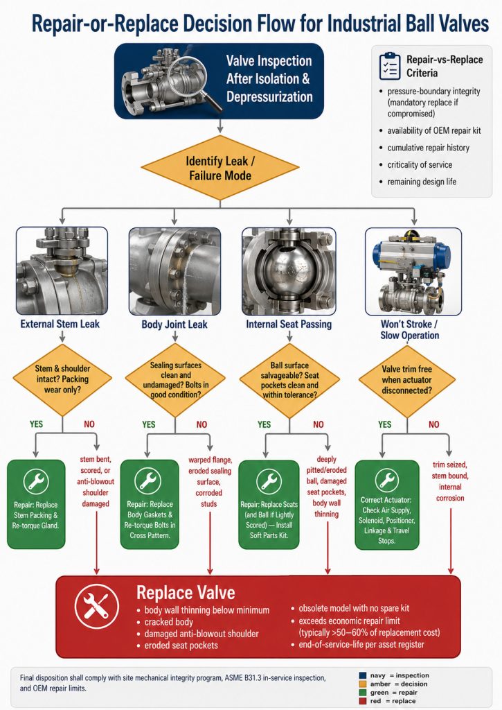
Know When Replacement Is the Better Repair
Repair is not a win if the valve can no longer protect the pressure boundary, close reliably, or match the process conditions. From a manufacturer’s perspective, the most important repair decision is knowing when not to continue.
The table below helps maintenance and procurement teams separate serviceable faults from conditions that should trigger replacement review.
| Finding after inspection | Repair decision | Verification point |
|---|---|---|
| Stem seepage with a smooth stem and serviceable packing area | Adjust or replace packing with compatible parts | Confirm smooth operation and no visible leakage under controlled return-to-service conditions |
| Internal passing with undamaged ball surface | Replace seats and inspect cavity cleanliness | ISO 5208:2015 addresses tests used to establish pressure boundary integrity and verify valve closure tightness and closure mechanism adequacy |
| Cracked body, severe corrosion, damaged threads, or distorted end connection | Replace the valve or pressure-retaining body assembly | ASME B16.34 covers pressure-temperature ratings, dimensions, materials, nondestructive examination, testing, and marking for new flanged, threaded, and welding-end valves |
| Project specification requires formal inspection and testing | Follow the purchase specification instead of relying on informal checks | The API source inspection guide lists API Std 598 examinations and tests such as shell, backseat, low-pressure closure, high-pressure closure, and visual casting examination for standard metallic valves when specified |
The core judgment is simple: repair soft parts when the metal pressure-retaining parts and sealing geometry are still sound. Replace or reselect when the failure points to body integrity, wrong materials, repeated seat damage, or a valve design that cannot be serviced safely.
Test the Repaired Valve Before Return to Service
A repaired valve should be verified before it is treated as reliable again. The level of testing depends on valve size, service criticality, available equipment, project specification, and whether the valve is being returned to the same duty or replaced in kind.
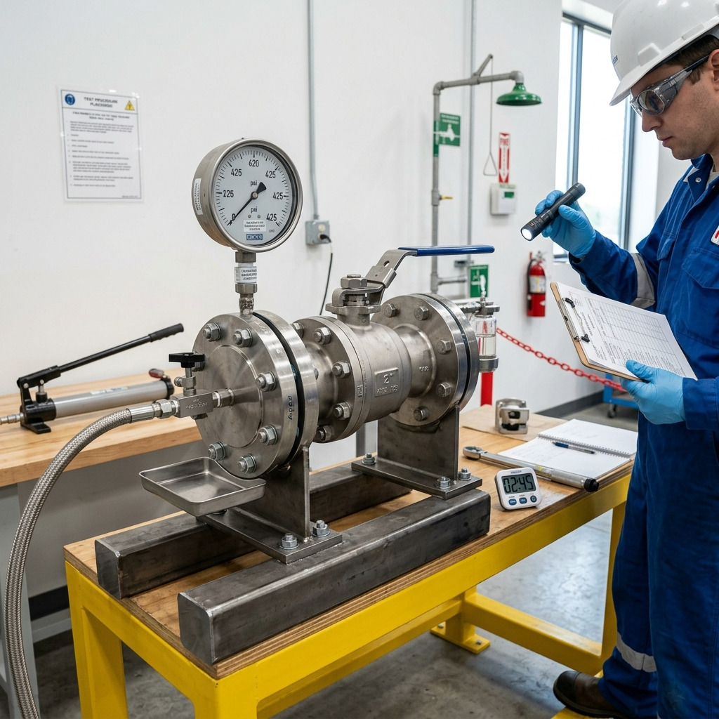
Bench testing
If a bench test is available, use the applicable project standard, pressure limit, test medium, and hold time. Do not assume that a repaired valve should be tested beyond its rated conditions; over-testing can damage soft seats or create a misleading result.
Inspect stem packing, body joints, end connections, and closure performance. A valve that passes a casual visual check but fails closure tightness may still cause process losses after installation.
Controlled field return
When only field verification is practical, pressurize gradually and monitor the repaired areas. Check the stem, body joint, downstream pressure, actuator movement, and handle feel before returning the line to normal operation.
Record what was replaced, what was inspected, and what conditions were observed. That record helps decide whether future failures are maintenance issues, material compatibility issues, cycling issues, or signs that the valve selection should be reviewed.
Conclusion
How to repair a ball valve is not mainly a tool question; it is a safety, diagnosis, materials, and verification question. A successful repair starts with isolation and depressurization, then follows the evidence: packing leak, seat damage, body joint leak, stuck movement, or a valve that should be replaced instead of rebuilt.
RUITO’s position is that repair decisions should protect pressure-boundary integrity first and project cost second, because a cheap seal change is not a saving if the valve no longer matches the duty. If your team is comparing repair, replacement, seat material, valve type, pressure class, or connection options, you can share the operating conditions and drawings to discuss valve specifications with RUITO.
FAQ
Can you repair a ball valve without removing it?
Sometimes, but only if the valve design and fault allow it. Stem packing adjustment or service on some three-piece and top-entry valves may be possible in place, while many two-piece or threaded designs need removal for safe internal repair.
Why does a repaired ball valve still leak internally?
The usual reason is that the ball, seats, or seat pockets were not actually restored. A scratched ball, wrong seat material, debris in the cavity, uneven body compression, or misaligned actuator can let flow pass even after new soft parts are installed.
Can PTFE seats be replaced with metal seats during repair?
Usually no. Metal-seated ball valves require different ball finishing, seat loading, torque, and often different design assumptions, so a soft-seated valve should not be converted casually during maintenance.
How tight should the stem packing nut be?
Tight enough to control leakage while keeping smooth operation. Use the valve manufacturer’s instruction or site maintenance procedure, because unsupported torque guesses can crush packing, increase operating torque, or damage the stem area.
When should procurement choose replacement instead of repair?
Replacement is the better choice when the pressure-retaining body is damaged, the ball surface is deeply scratched, compatible parts are unavailable, or the valve keeps failing because it does not match the media, temperature, cycling, or pressure conditions.