

Engineered for Fire Sprinkler & Commercial HVAC Grooved Piping
Fast mechanical assembly, dependable zero-leakage shutoff, and strict system compatibility across valve ends, groove profiles, couplings, and gaskets.
Send your pipe OD, groove standard, and working pressure — get a factory-matched quotation.
A Grooved Piping System Demands More Than Just an On-Off Butterfly Valve
Valve ends, pipe groove profiles, mechanical couplings, and resilient seals must operate as an interconnected assembly to guarantee leak-free containment and pressure integrity.
Precise Groove Interface Matching
Every grooved end butterfly valve must conform exactly to your pipe outside diameter (OD), groove depth, coupling housing, and gasket profile rather than generic nominal diameter (DN) alone.
Governed by the Lowest Rated Component
Working pressure cannot be determined by the valve casing rating in isolation. The valve body, groove standard, mechanical clamp, and sealing ring must be appraised collectively to establish true boundaries.
Application-Driven Trim Configuration
Fire sprinkler networks, HVAC chilled circuits, and potable utilities possess distinct chemical, thermal, and compliance criteria. Component trims must be configured specifically to your fluid medium.
Uncertain about pipe OD standards, groove profiles, or coupling compatibility?
Consult with Our Piping EngineersSeamlessly Integrating Butterfly Valves into Grooved Piping Networks
From mechanical coupling fit to bi-directional shutoff, combining valve durability with grooved system standards in a single assembly.
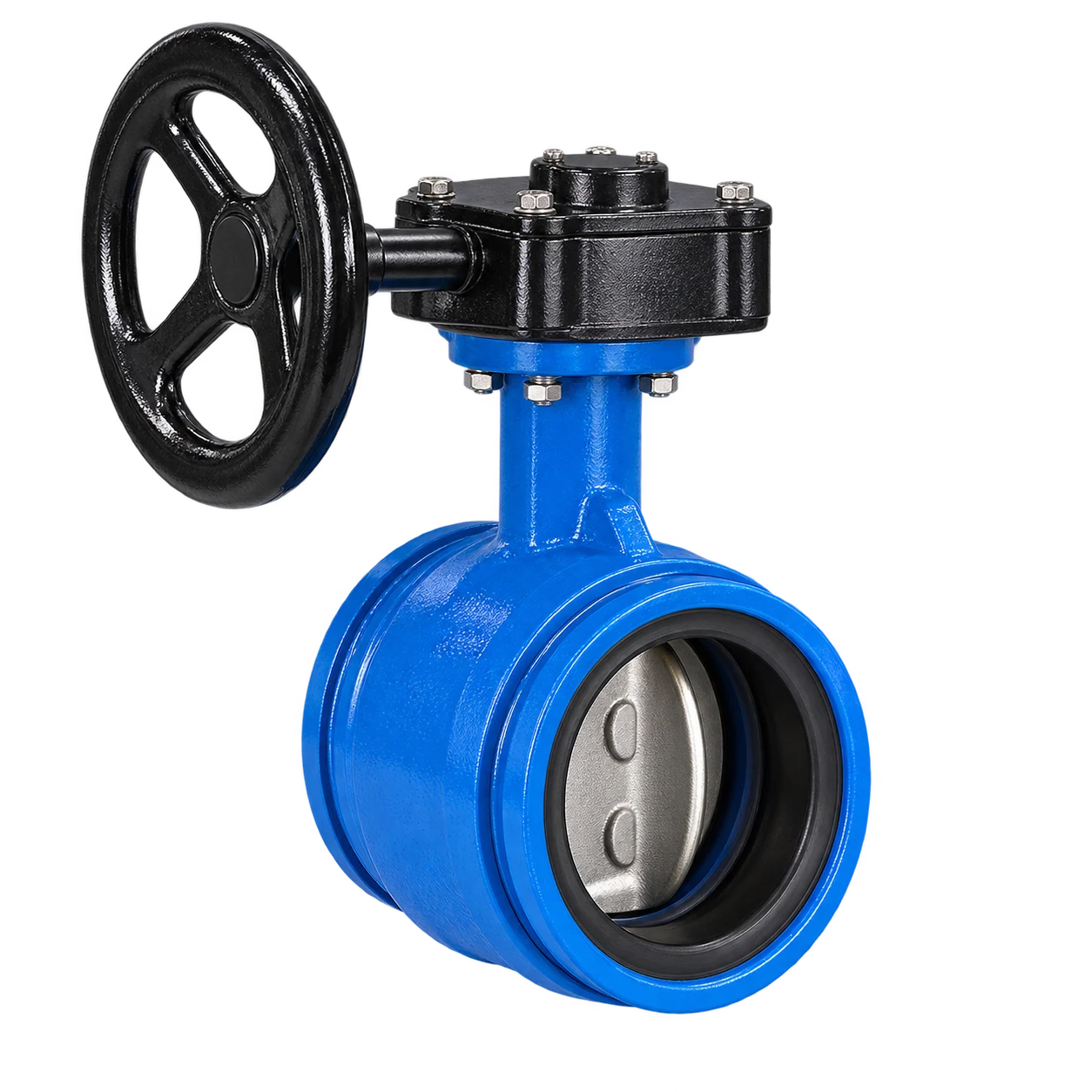
Direct Alignment with Grooved Piping Standards
Precision-machined exterior end grooves accommodate standardized mechanical couplings directly, eliminating flange welding, bolt alignment delays, and gasket slippage.
Tailored for Commercial Water & HVAC Services
Optimized for chilled water, condenser loops, domestic hot water distribution, and low-pressure utility lines with resilient bi-directional zero-leakage shutoff.
Standardized DN50–300 & PN10/PN16 Rating Span
Consistent face-to-face and groove profiles covering nominal diameters DN50 through DN300, certified for non-shock cold working pressures up to 16 bar.
Application-Specific Configuration Verification
Factory-matched trim assemblies including 304/316 stainless disc options, resilient EPDM or NBR seats, and ISO 5211 top flanges for standardized actuation.
Need exact dimensional drawings and coupling interface datasheets?
Download Engineering Value Brief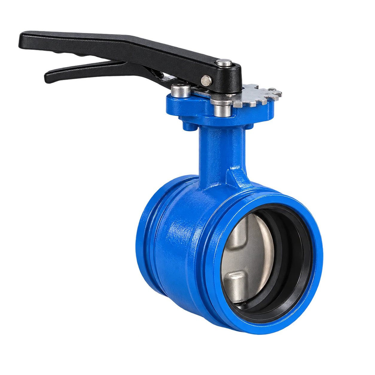
Grooved End Butterfly Valve Engineering Overview
Resilient seated quarter-turn butterfly valve engineered for swift mechanical coupling and reliable fluid isolation.
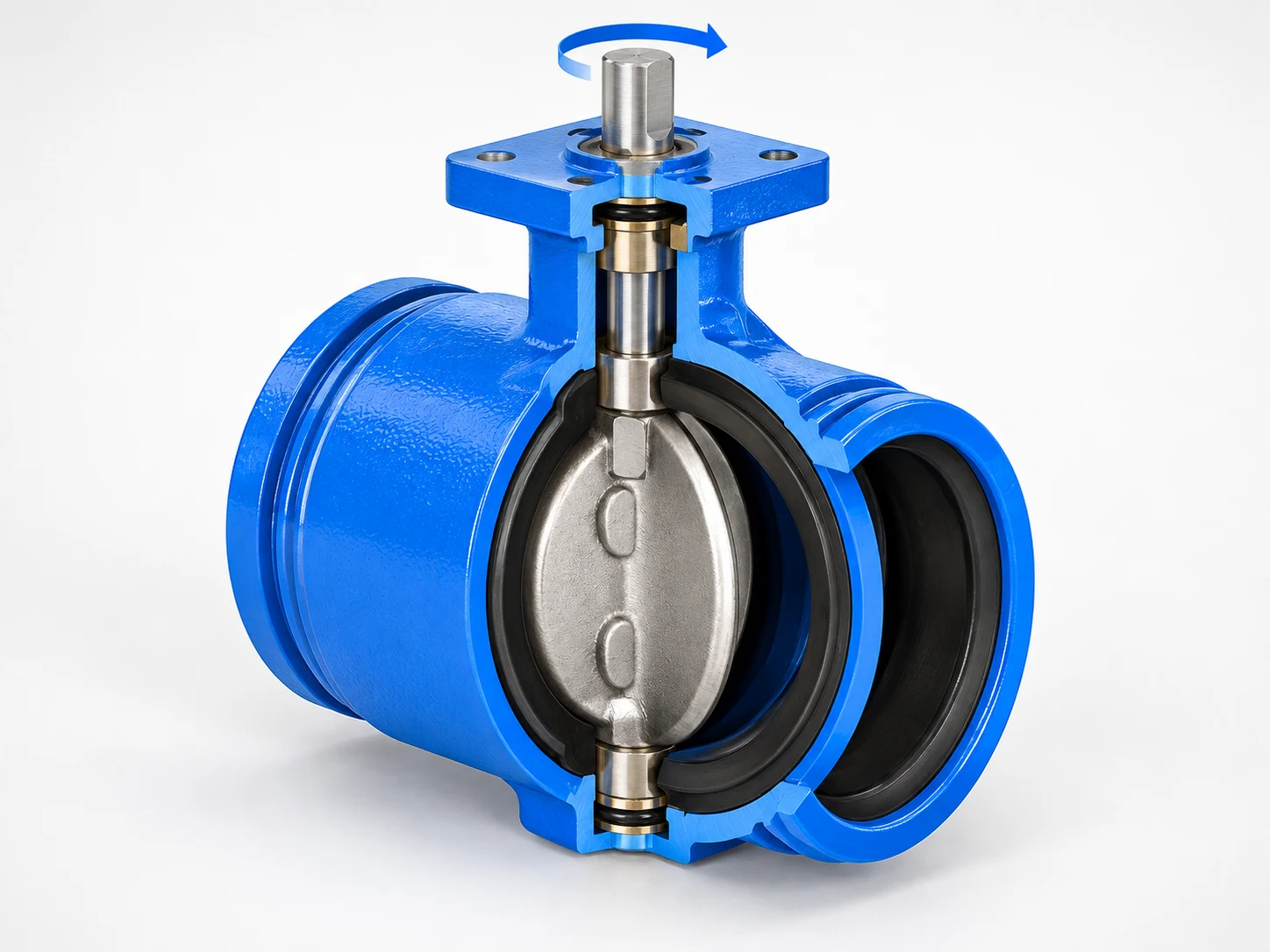
Designed specifically for mechanical piping environments, the RUITO grooved butterfly valve connects directly into grooved piping runs with standard couplings. A concentric disc rotates 90 degrees inside an elastomer-lined body, creating dependable bubble-tight shutoff across DN50–300 spans rated up to PN16 pressure thresholds. To compare other connection styles, explore our butterfly valve range.
Require verified CAD models or valve face-to-face dimensions?
Request Technical Specification SheetEngineered for Water & Fluid Circulating Grooved Systems
RUITO grooved end butterfly valves deliver fast installation and reliable flow isolation across commercial fire protection, building services, and industrial cooling loops.
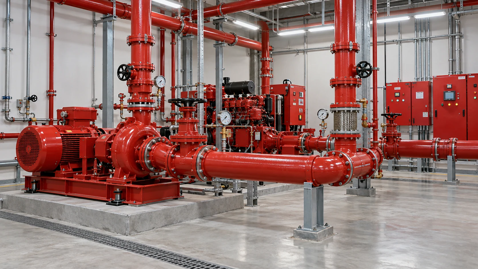
Fire Protection Systems
Non-Freezing Fire WaterEngineered for grooved wet/dry fire sprinkler networks and pump risers. Trims adhere to rigorous market approval standards to guarantee reliable emergency shutoff.
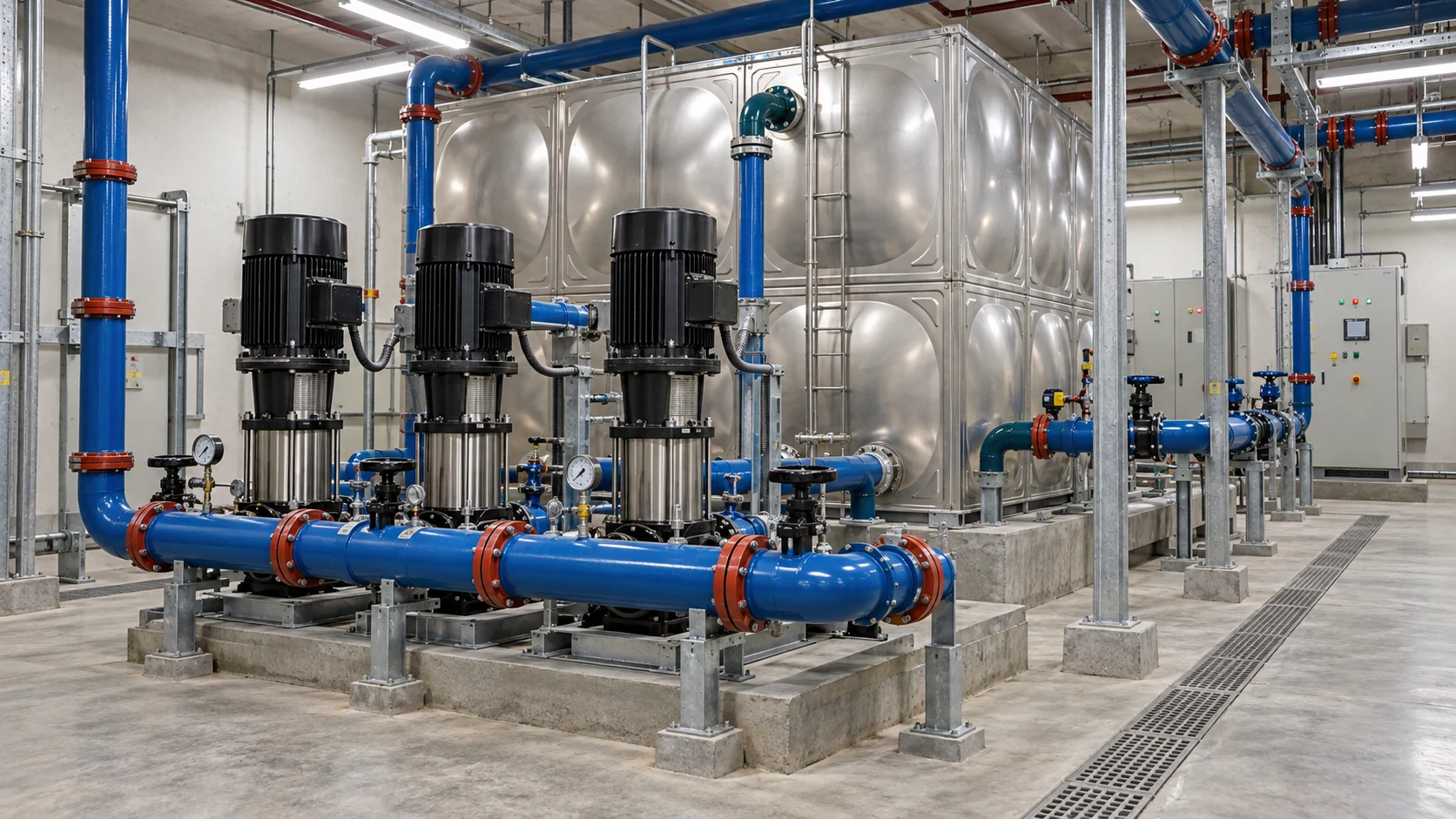
Commercial Building Water
Clean Ambient WaterSeamlessly couples into MEP distribution mains, pump manifolds, and filtration circuits with zero bolt torque alignment delays or gasket pinching.

HVAC / Cooling Circuits
Chilled Water & Glycol (0–40%)Optimized for chiller headers and cooling tower loops. Compatible with inhibited glycol mixtures while sustaining bubble-tight shutoff against thermal cycling.
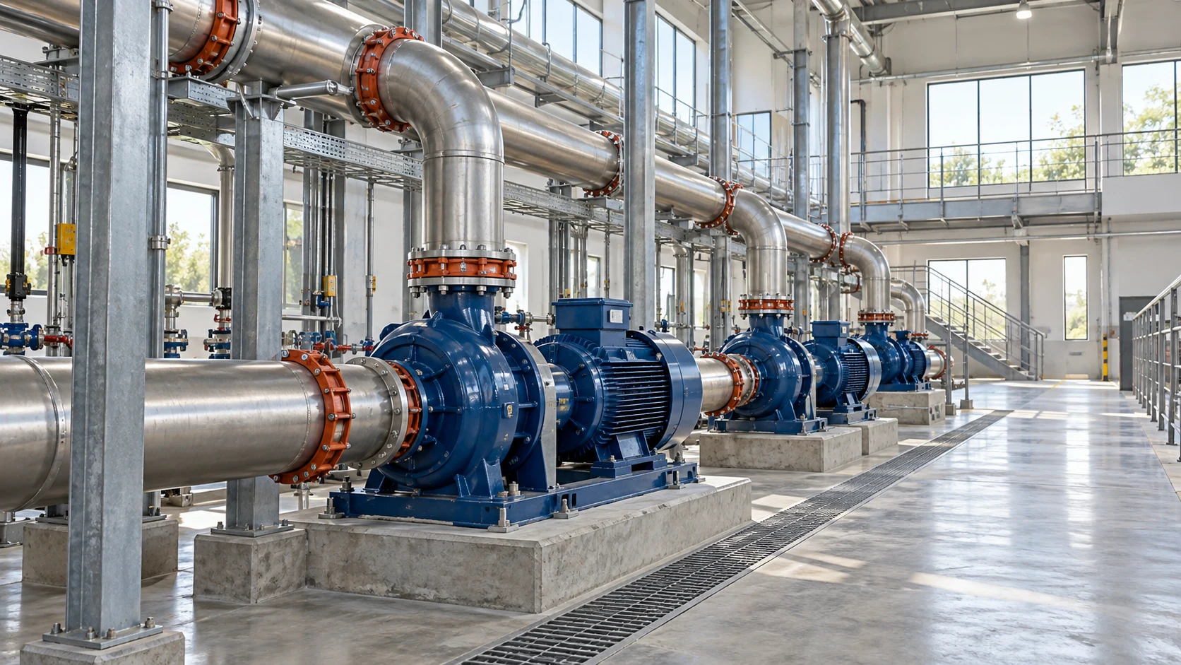
Potable Water Contact
Certified Drinking WaterConfigured with certified hygienic rubber linings and non-toxic internal coatings compliant with municipal drinking water requirements and regulatory health codes.
Have a specific fluid chemical composition or unique project operating medium?
Verify Your Application CompatibilityDefined Sizing, Pressure Ratings & Thermal Boundaries
Grooved end butterfly valve selection requires simultaneous verification of pipeline dimensions, system pressure, and working fluid temperatures without cross-extrapolating maximum thresholds.
Covering primary distribution and utility branch diameters across commercial plumbing, HVAC, and fire pump rooms.
Configured for cold working pressures up to 16 barg, subject to joint coupling and pipe wall schedule ratings.
Optimized for non-freezing clean water, fire fighting mains, and verified low-concentration secondary cooling circuits.
Verified Operating Conditions by Application Domain
Fire Protection & Building Water Mains
Working Temp: 5–60°C | Media: Non-freezing potable/utility water and approved fire extinguishing circuits under verified coupling clamping force.
HVAC Closed Loops & Cooling Towers
Working Temp: 5–60°C | Working Pressure: ≤10 barg
Inhibited aqueous glycol solutions up to 40% concentration. Prior confirmation of pH and inhibitor corrosion chemistry required.
Potable Water Contact Assembly
Working Temp: 5–40°C | Demands certified elastomeric seat compound, non-leaching body coating, and regional municipal health approvals.
System Rating Governed by the Lowest Rated Element
When installed into piping networks, safe working pressure is never determined by valve body testing alone. Operating thresholds must be appraised across all four interconnected components:
Uncertain if your system pressure and temperature exceed rated mechanical limits?
Request System Operating Limits VerificationVerify Every Grooved Interface Detail Before Sizing
Grooved end butterfly valve compatibility must be confirmed based on actual pipe outer dimensions, groove cut profile, coupling housing, and elastomeric gasket—not merely nominal DN diameter.
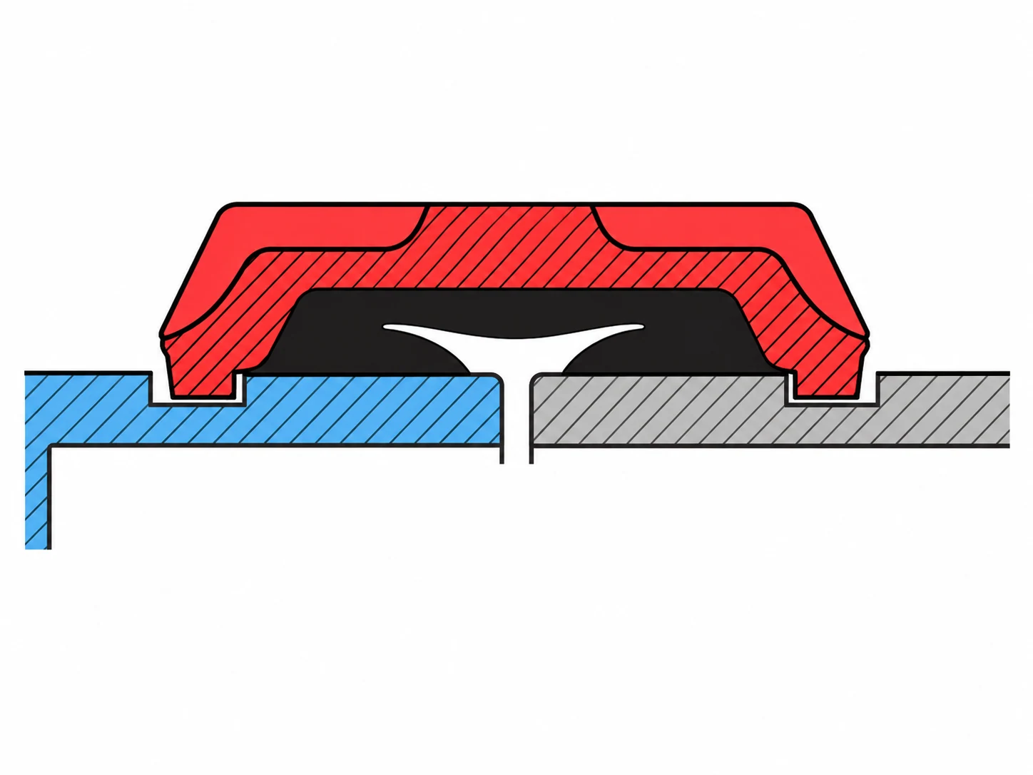
Fig 1. Precision Mechanical Coupling Exploded Alignment: Pipe End → Gasket → Coupling Clamp → Valve Grooved End
Confirm Actual Pipe Outside Diameter (OD)
Provide your exact field pipe outside diameter in millimeters or inches rather than nominal DN/NPS alone. The valve grooved collar must interface precisely with the specific pipe wall standard.
Define Machined or Rolled Groove Profile
Clarify whether pipe ends feature cut grooves or roll grooves per AWWA C606. Differing groove geometry alters seating contact and mechanical coupling engagement depth.
Match Mechanical Coupling Housing Specs
Specify planned rigid or flexible mechanical coupling types and manufacturer series to verify radial key engagement dimensions against the valve exterior grooved shoulders.
Verify Elastomeric Gasket Compound
Select matching EPDM, NBR, or specialized fluorocarbon sealing rings tailored to working media, thermal range, and pipeline chemical additives for hermetic joint integrity.
Unsure about coupling clamping tolerances or pipe wall thickness compatibility?
Submit Piping Groove Drawing for VerificationExplicit Material Grade Configuration for Every Wetted Component
Standard water-service grooved butterfly valves employ ductile iron bodies, CF8M stainless discs and shafts, and resilient EPDM seats to ensure mechanical strength and corrosion resistance.
High-tensile ductile iron pressure casing providing rugged mechanical impact resistance, robust hydraulic hoop strength, and structural stability across piping networks.
Precision-molded elastomer seat liner delivering resilient 360° bubble-tight shutoff against chilled water, domestic utilities, and anti-freeze fire protection systems.
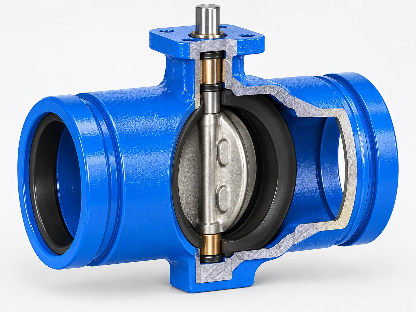
Cast CF8M marine-grade stainless disc offering superior hydrodynamic flow efficiency, erosion prevention, and chemical immunity in treated building water circuits.
Precision-ground two-piece drive stem transmitting high actuation torque smoothly with minimal hysteresis, blow-out proof retention, and zero stem leakage.
Material Selection Governed by Circulating Media
The standard trim combination (Ductile Iron + CF8M + EPDM) is configured specifically for clean water, non-potable building services, and fire fighting circuits. When specifying for glycol loops, exact glycol ratio (0–40%), corrosion inhibitor packages, system pH, and viscosity must be verified prior to approval.
Potable Water Contact Compliance
Projects requiring contact with municipal drinking water mandate certified hygienic rubber formulations, certified epoxy interior coatings, and specific temperature ceilings. Standard industrial water trims cannot be substituted for potable water applications without regional compliance certification.
Need custom trim materials such as Aluminum Bronze disc or NBR seat for specialty fluids?
Request Custom Material SpecificationIntegrating Valve Installation Directly into Grooved Piping Assembly
Built around exterior end grooves, roll/cut groove dimensions, mechanical couplings, and resilient elastomeric gaskets to form a cohesive pipeline joint. For projects using companion flanges rather than grooved couplings, compare wafer butterfly valves and confirm the flange and disc-clearance requirements.
Verify Pipe Outer Diameter & Groove Profile
Clarify pipe OD and AWWA C606 groove geometry prior to hoisting.
Match Mechanical Coupling & Gasket
Ensure housing key conforms to valve groove collar and gasket elastomer matches system fluid.
Complete Valve & Piping Assembly
Position valve disc in partial open orientation to avoid seat pinching during coupling bolt torqueing.
Need step-by-step mechanical room installation and bolt torque guidelines?
Download Grooved Installation GuideMatch Actuation to Dynamic Seating Torque & Closing Differential Pressure
Grooved end butterfly valves accommodate manual levers, worm gear handwheels, pneumatic actuators, and electric motors—sized strictly to operating differential pressure rather than nominal port diameter alone.
Actuation Sizing Governed by System Fluid Dynamics
Operating torque varies dynamically with line pressure, disc position, media velocity, and seat friction coefficient. RUITO provides verified hydrodynamic torque curves.
Lever Operated / Manual Hand Lever
For quick quarter-turn throttling and on/off isolation up to DN150.
Worm Gear Operated / Heavy-Duty Gearbox
Self-locking precision gearbox eliminating water hammer on DN150–300 spans.
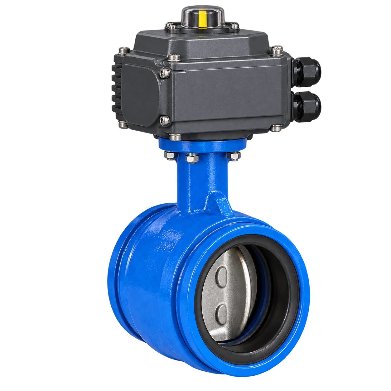
Electric Actuated / Motorized Quarter-Turn
Multi-voltage on/off and modulating 4–20mA feedback automation.
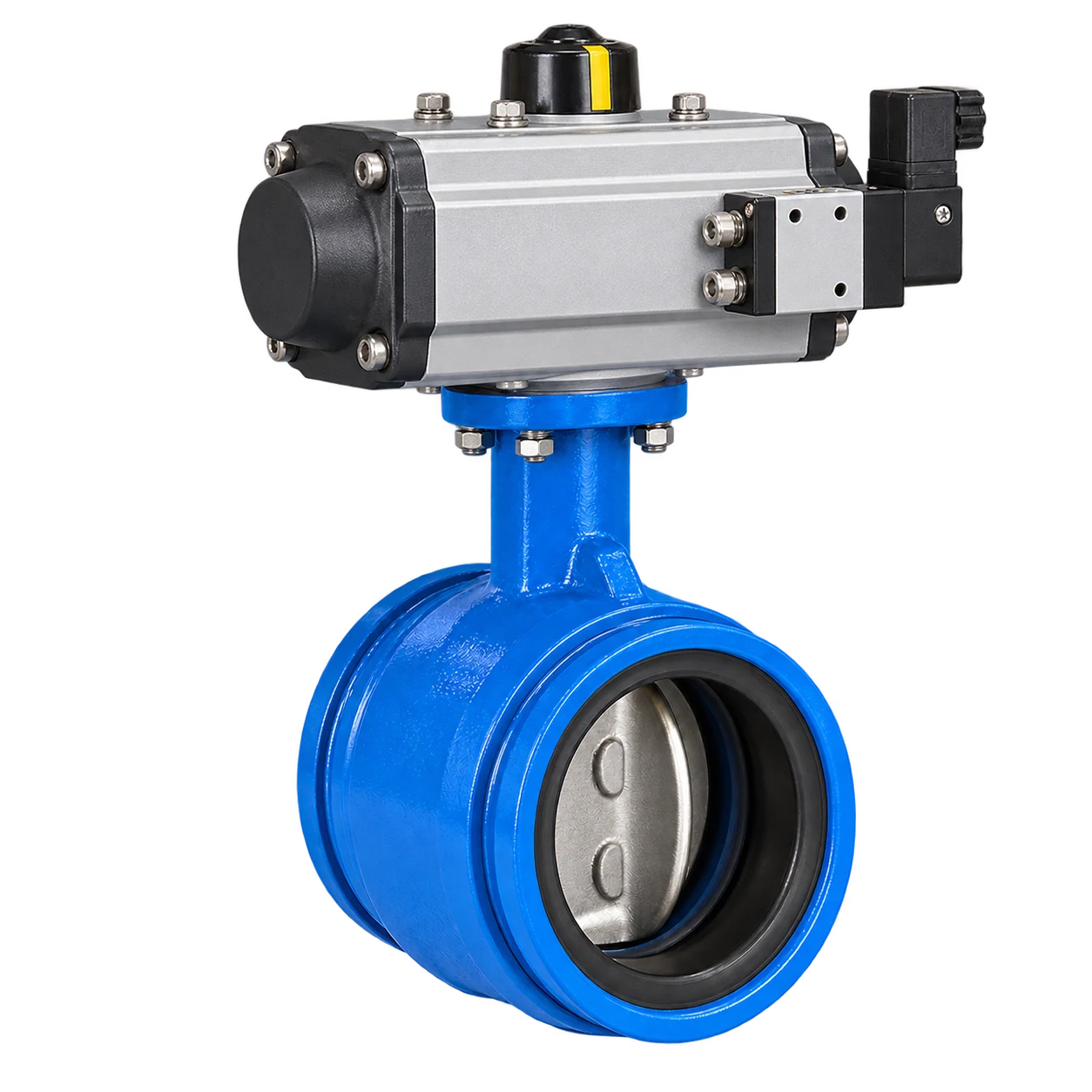
Pneumatic Actuated / Rack & Pinion Cylinder
High-speed double-acting or spring-return failsafe actuation.
Need actuator sizing calculations or ISO 5211 bracket mounting dimensions?
Request Actuation Selection DataEvery Valve Undergoes Rigorous Hydrostatic & Bubble-Tight Inspection
Grooved end butterfly valves are factory proof-tested across shell body integrity and resilient seat closing thresholds per EN 12266-1 and ISO 5208 standards with recorded hold durations. Review RUITO's manufacturing and inspection capabilities when qualifying a supplier for the project.
1.5× nominal rating hydrostatic test verifying body casting, shaft seals, and casing wall integrity.
1.1× cold working pressure verifying 360° elastomer seat seal for zero-drop bubble-tight shutoff.
1.5× PN16 rating validating ductile iron structural strength against hydraulic shock and surge loads.
Bi-directional differential seat shutoff examination matching maximum closing differential pressures.
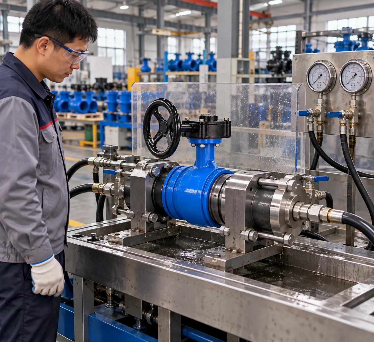
Shell Pressure Test
Hydrostatic Pressure ExaminationValve disc positioned in partially open state. Full test pressure applied into body cavities to detect any porosity, structural weeping, or external casing weeping.
Seat Leakage Test
Bi-Directional Shutoff VerificationDisc closed under rated torque. Hydrostatic pressure applied sequentially in both flow directions with zero allowable seat seepage to confirm hermetic seal.
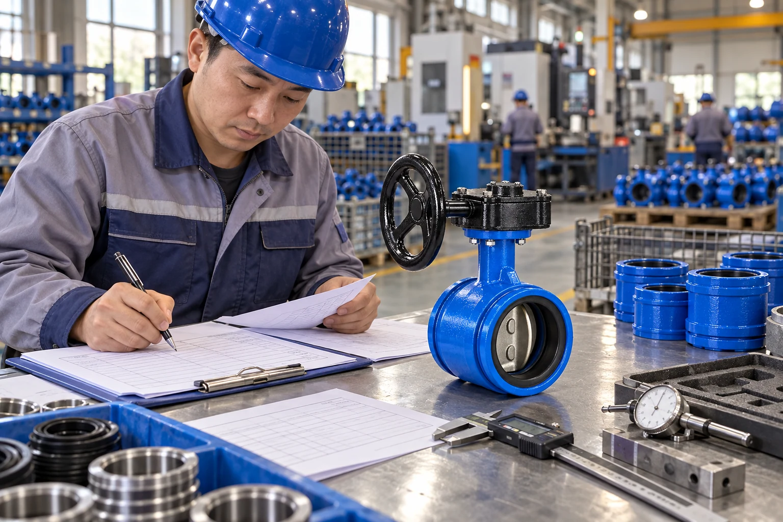
Inspection Record
Certified Test TraceabilityTest parameters, duration holding records, and digital signoffs archived per batch serial numbers for EN 10204 3.1 inspection documentation traceability.
Need hydro-test duration parameters or EN 10204 3.1 inspection certificate samples?
Request Pressure Testing Inspection DataDedicated Operating Envelopes Tailored to Project Environments
Grooved end butterfly valves serve fire, building services, and HVAC fluid circuits—yet operating temperature, medium chemistry, pressure limits, and regulatory approvals must be validated per specific installation.
Fire Protection Systems
Non-Freezing Fire WaterRequires verified approvals for target jurisdictions. Valve, groove profile, coupling housing, and gasket must be appraised collectively as an interconnected fire water barrier.
HVAC / Circulating Water
Clean Water & Glycol (0–40%)For glycol circulating loops, fluid pH, corrosion inhibitors, solution density, and kinematic viscosity must be confirmed to ensure hydrodynamic stability and seat durability.
Commercial Building Water
Ambient Clean & Utility WaterEngineered for commercial MEP utility lines. System operating pressure must confirm to pipe groove style, coupling rating, and pipe schedule wall thickness.
Uncertain if your fluid chemical concentration or operating limits match standard configurations?
Consult with Application SpecialistsRigorous Compliance Framework Governing Valve Design, Grooved Coupling & Pressure Testing
Grooved end butterfly valves adhere to established European and international engineering standards, ensuring structural integrity, dimensional interchangeability, and certified batch traceability across every installation.
Governs mechanical dimensioning, minimum casing shell thickness, blowout-proof stem retention, and torque transmission criteria for industrial metallic butterfly valves.
Specifies precise cold-roll and cut groove tolerances, gasket seat surface finish, and shoulder dimensions to achieve seamless interchangeability with standard mechanical grooved couplings.
Defines mandatory factory hydrostatic shell pressure proofing (1.5× PN) and resilient seat bi-directional leakage verification (1.1× PN) with recorded hold duration.
Comprehensive Project Acceptance & Technical Submittal Package
Technical qualification requires documentation matching exact manufactured trim configurations:
- Size Range Matrix
- Pressure Class Ratings
- Thermal Range Limits
- Wetted Material Grades
- Actuation Torque Curves
- Machined Groove Drawings
- Pipe OD Matching Sheets
- Coupling Clamping Clearances
- Elastomeric Gasket Approvals
- Factory Hydrostatic Test Logs
- Seat Leakage Certificates
- EN 10204 3.1 Traceability
- Pre-Shipment Inspection Reports
- Fire Protection Listings
- Potable Water Sanitization
- Third-party ISO 9001 Compliance
- CE / PED Pressure Directives
Need technical compliance documentation or EN 10204 3.1 certificate templates for project submittal?
Request Standard Compliance Submittal PackageComprehensive Operating Inputs for Precise Valve & Grooved Interface Sizing
Accurate valve selection requires thorough alignment of operating fluid chemistry, temperature extremes, shutoff differential pressure, and specific pipe groove geometry.
Circulating Media & Fluid Chemistry
Engineering Tip: Specify exact glycol concentration (e.g., 30% v/v), inhibitor packages, and pH balance to confirm elastomer seat compatibility.
Example: 30% Propylene Glycol Chilled LoopContinuous Working Temperature
Engineering Tip: Provide dynamic fluid operating range rather than ambient mechanical room temperature.
Example: Working Temp 8°C to 45°C ContinuousSystem Pressure & Closing Differential
Engineering Tip: Nominal PN class defines maximum shell rating; actual actuator selection depends strictly on closing DP.
Example: 8.5 barg Line / 6.0 bar Closing DPPipe Outside Diameter & Schedule
Engineering Tip: Always confirm actual pipe OD in mm/inches to avoid imperial/metric groove sizing mismatches.
Example: DN100 / Actual OD 114.3 mmGroove Specification & Coupling Brand
Engineering Tip: Provide coupling brand and series to ensure joint radial engagement matches valve shoulders.
Example: Roll Grooved AWWA C606 / Rigid CouplingActuation Method & Project Standards
Engineering Tip: Indicate whether automated modulating signals (4–20mA) or spring-return failsafe are required.
Example: Worm Gear Handwheel + ISO 5211 PadReady to size your grooved butterfly valves against real mechanical room parameters?
Review Your Operating Parameters with Engineering
Tell Us Your Operating Conditions — We Will Match Your Grooved Butterfly Valve
Submit pipe diameter, circulating fluid, temperature-pressure boundaries, and grooved interface specs for certified engineering validation.
Whether procuring for fire sprinkler networks, building services, or industrial HVAC loops, accurate valve sizing begins with actual line parameters. Provide your specs and our team will evaluate wetted trims, pressure ratings, and grooved coupling compatibility.
DN50–300, PN10 / PN16
Covering core commercial and industrial sizing spans.
Grooved Interface Verification
Verifying cut/roll grooves, pipe OD, couplings, and gaskets against AWWA C606.
Fluid & Media Matching
Formulated for non-freezing clean water, fire protection, and verified glycol loops.
Hydrostatic & Bubble-Tight Testing
Factory shell (1.5x) and seat shutoff (1.1x) inspection documentation.
Multi-Actuation Capability
Lever handles, worm gearboxes, electric 4–20mA, or pneumatic failsafe cylinders.
Get a Technical Quote & Sizing Verification
Complete the project parameters below and our engineering team will provide custom quotation and interface drawings.