RUITO Header Component
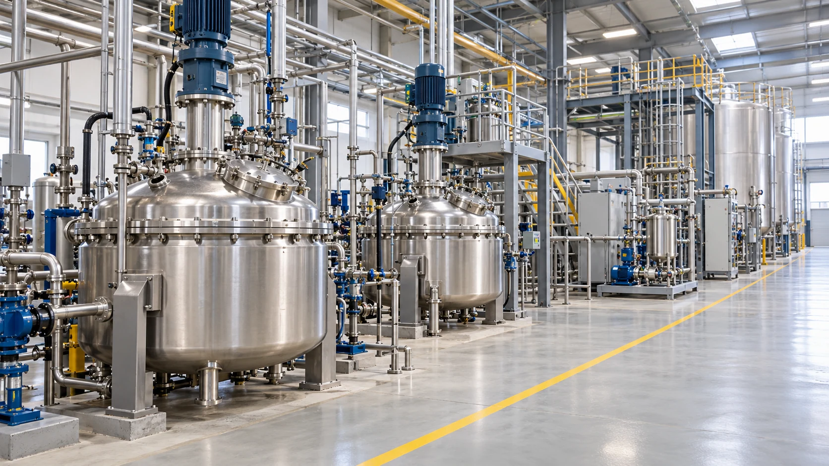
Chemical processing plant with reactor vessels, pipe racks, and organized corrosion-resistant process lines.
PTFE Lined Butterfly Valve

Continuous PTFE Lined Butterfly Valves for Corrosive Media Isolation

Engineered with a seamless, high-integrity PTFE wetted barrier for chemical batching, acid-alkali transfer, and aggressive dosing lines—customized to specific media concentration, temperature, and pressure boundaries.

DN25–DN300  |  Rated PN10  |  Continuous PTFE Wetted Lining  |  Manual, Pneumatic & Electric Actuation
Need immediate engineering validation for your plant conditions?

Why Do Corrosive Chemical Pipelines Require Dedicated PTFE Lined Butterfly Valves?

Selecting valves for acids, alkalis, and oxidative dosing streams cannot rely solely on standard pressure classes or basic body alloys. Fluid composition, concentration, thermal cycles, and all wetted surfaces must be evaluated as an interdependent engineered system.

Media Compatibility Boundaries

Chemical solutions exhibit strict compatibility thresholds. Corrosive media such as NaOH, HCl, H₂SO₄, and NaClO require individual verification rather than generic "corrosion-resistant" classifications.

Continuous Wetted Isolation

Corrosive fluid contacts the disc, body cavity, and shaft seals. A seamless PTFE lining encapsulates all contact zones, eliminating exposure and preserving primary metallic load-bearing housings.

Coupled PT-Concentration Limits

Chemical envelope boundaries are not independent peak values. True selection demands simultaneous matching of solution concentration, operating temperature, differential pressure, and seal resilience.

Lining Integrity Verification

Liner thickness consistency, spark pinhole tests, flange flare sealing, and resilient energizer condition govern service life, necessitating unit-by-unit dielectric and visual inspection.

Consult our chemical process valve specialists to verify your fluid parameters:

Request Engineering Evaluation
PTFE Lined Butterfly Valve | Module 5 Continuous PTFE Lining

Engineered Superiority of PTFE Lined Butterfly Valves

Built upon a continuous PTFE wetted isolation architecture, combined with a compact quarter-turn profile, versatile connection styles, and adaptable actuation packages—providing an engineer-verified isolation solution tailored for aggressive chemical liquid pipelines.

Continuous PTFE Wetted Isolation

The internal flow channel is fully encapsulated by an uninterrupted virgin PTFE lining, pairing seamlessly with the coated disc to shield primary load-bearing metal from corrosive contact.

PTFE Encapsulated Disc Profile

All disc wetted geometries feature thick, uniform PTFE encapsulation, working integrally with the body liner to establish an uninterrupted chemical defense path for severe acid and alkali lines.

Wafer & Lug Connection Options

Engineered in both wafer and full-lug body configurations to align with pipeline piping layouts, end-of-line isolation demands, and mating flange standards across chemical skids.

Flexible Actuation Modularities

Configured precisely to break-away torques and operating cycles with 10-position hand levers, worm gearboxes, pneumatic double-acting/spring-return actuators, or smart electric units.

Ready to integrate these chemical isolation advantages into your pipeline?

Configure Your PTFE Lined Valve
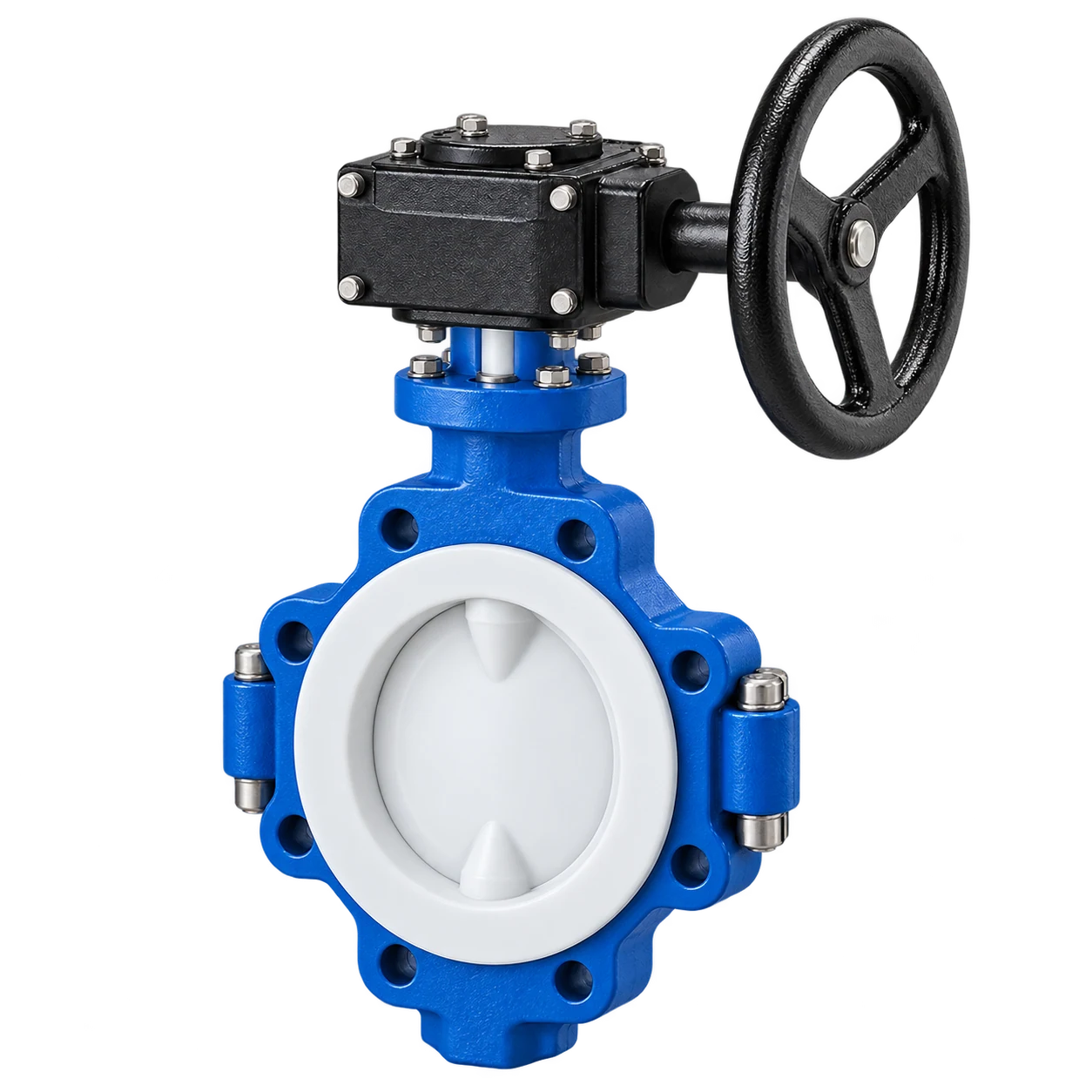
Blue PTFE lined butterfly valve with a worm gearbox, continuous white liner, and a fully encapsulated white disc.

What Is a PTFE Lined Butterfly Valve?

A PTFE Lined Butterfly Valve is an engineered quarter-turn isolation valve designed specifically for aggressively corrosive chemical liquid services. Through 90-degree disc rotation, it provides low-torque pipeline shutoff while completely sealing hazardous media away from external ductile or metallic pressure-retaining bodies.

Widely deployed across chemical batching, precise dosing, industrial acid pickling, and alkali transfer loops, the valve accommodates wafer or lug connection standards and seamlessly couples with manual levers, gearboxes, or automated control actuation packages. Explore our butterfly valve configurations for an overview of body, sealing, and actuation options.

Primary Function

Tight on/off shutoff and positive isolation for corrosive chemical streams.

Typical Systems

Chemical mixing, acid dosing skids, industrial washings, and transfer lines.

Operation Modes

Configurable with manual lever, worm gear, pneumatic, or electric actuation.

Explore complete dimensional drawings and engineering configurations:

Download Product Specification Sheet
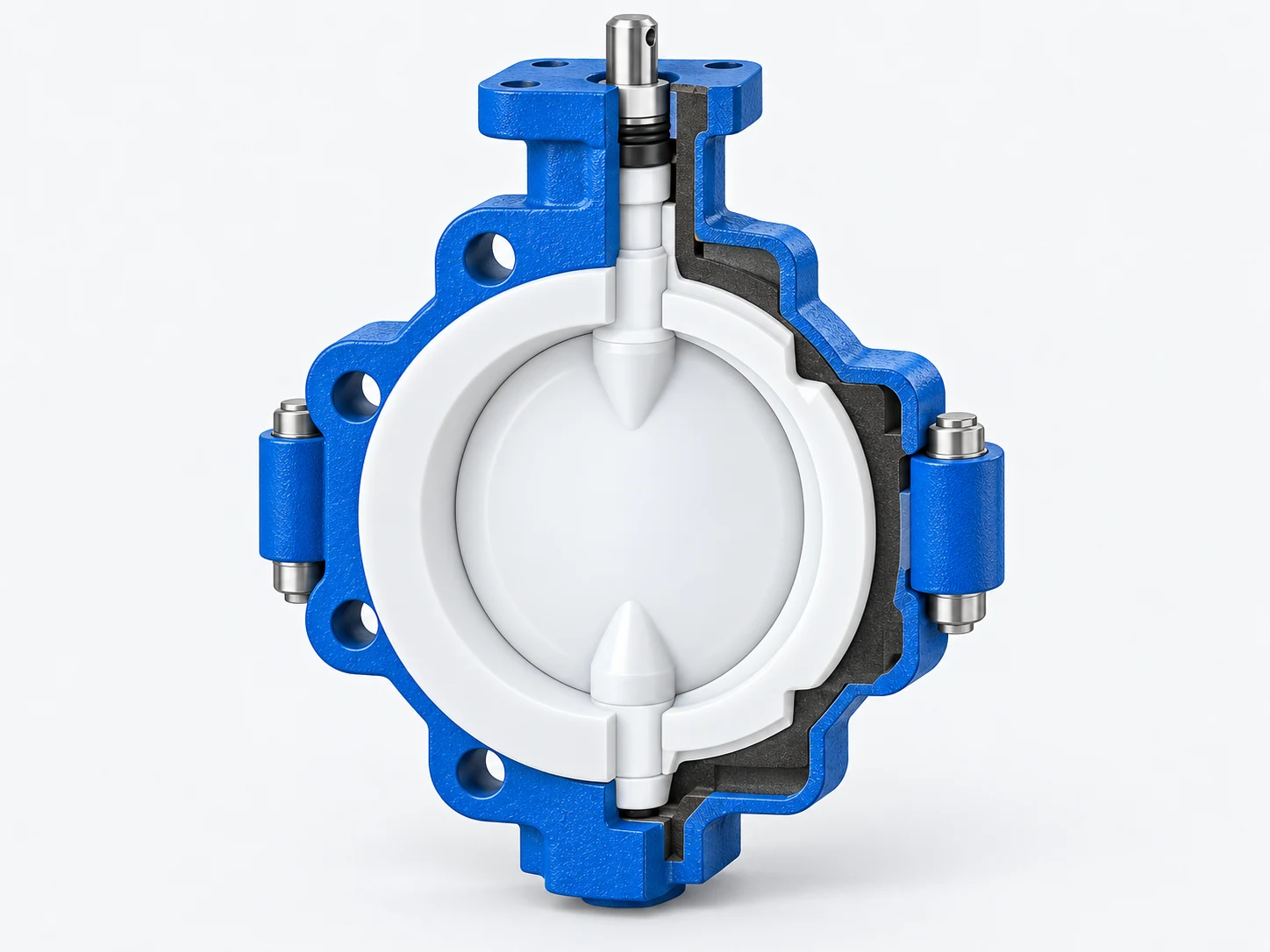
Sectional view of a PTFE lined butterfly valve showing the continuous liner, white encapsulated disc, supporting body, and stem seal transition.
01 Virgin PTFE Body Liner
02 Encapsulated Disc
03 Flange Flare Collar
04 Stem Seal Transition

Seamless Isolation Defending Load-Bearing Components

The valve incorporates a continuous virgin PTFE wetted lining coupled integrally with a PTFE-encapsulated disc. Engineered with nominal lining thicknesses from 2 mm to 5 mm, all wetted contours ensure aggressive chemical liquids never compromise primary ductile iron or stainless housings.

01

Continuous Body Liner

High-density virgin PTFE encapsulates the complete internal flow passage, establishing an unbreached chemical barrier between process stream and external shell.

02

PTFE Encapsulated Disc

The disc core is uniformly enveloped in compression-molded PTFE, creating a resilient wetted contact boundary that maintains chemical resistance even at 90° shutoff positions.

03

Flange Flare Sealing Collar

The liner smoothly flares over both raised mating faces, acting as an integrated gasket with piping flanges to safeguard pipeline joints under controlled bolting torque.

04

Dynamic Stem Seal Transition

Precision energizer rings and engineered shaft seals form an interdependent barrier around the stem entry, preventing fluid creep toward atmospheric packing chambers.

Need technical section drawings and dimensional cross-sections for your project review?

Request Detailed Engineering GA Drawings

Harmonized Metallurgy, Liners & Sealing Alloys

Material qualification encompasses the entire assembly. Pressure-retaining outer shells, virgin fluoropolymer liners, structural disc substrates, and resilient backing polymers are harmonized against exact chemical media and thermal limits. For a specified PFA lining package, compare our PFA-lined butterfly valves using the same medium, concentration, temperature, and pressure criteria.

Pressure Boundary

Ductile Iron & Carbon Steel

Engineered ductile iron (GGG40.3 / EN-GJS-400-18) or cast stainless steel (CF8 / CF8M) absorbs pipeline mechanical loads, piping bending stresses, and PN10 hydro ratings per project BOM.

Wetted Fluid Channel

Virgin PTFE / PFA Lining

Isostatically molded pure PTFE (or injection-molded PFA for extreme permeation resistance) provides a smooth, non-stick, non-contaminating surface impenetrable to concentrated acids and alkalis.

Disc Closure Element

PTFE Encapsulated CF8M

High-strength stainless steel core encapsulated with 2.5–3.5 mm virgin PTFE layer, or optional Hastelloy / Titanium unlined disc configurations for abrasive or specialized slurries.

Backing & Stem Seals

Silicone / FKM & V-Rings

Resilient VMQ Silicone or FKM energizing cushions behind the liner guarantee bubble-tight bi-directional seat resilience, accompanied by self-adjusting PTFE V-ring atmospheric packings.

Require tailored material combinations for non-standard chemical concentrations?

Consult Materials Engineering Specialist

Targeted Chemical Media & Concentration Thresholds

PTFE Lined Butterfly Valves require dedicated qualification based on defined aqueous fluid compositions and concentrations. Each chemical duty is isolated and verified individually—never summarized under ambiguous "acid and alkali resistance" claims.

Alkaline Service

NaOH

Sodium Hydroxide Aqueous Solution

10%–30%
Mass Fraction (w/w)

Engineered for caustic soda dilution, alkaline chemical dosing, and industrial clean-in-place circuits. Fluid additives, surfactants, and bath wash components must be cross-verified concurrently.

Acidic Service

HCl & H₂SO₄

Hydrochloric & Sulfuric Acids

HCl (w/w) 1%–20%
H₂SO₄ (w/w) 1%–30%

Hydrochloric and sulfuric acids demand independent chemical BOM protocols. One acid's performance parameters cannot be extrapolated to other acid compounds or varied halogen concentrations.

Oxidative Dosing

NaClO

Sodium Hypochlorite Aqueous Stream

0.5%–5%
Mass Fraction (w/w)

Dedicated for controlled sodium hypochlorite bleaching and oxidative disinfection dosing lines. Sizing requires verification of available chlorine levels, solution pH, and upstream stabilizing salts.

Need chemical resistance verification for your specific fluid composition?

Submit Fluid Compatibility Query

Dimensional Envelopes, Hydro Ratings & Thermal Limits

Baseline engineering specifications deliver full size coverage from DN25 through DN300, structural PN10 rating, and a design envelope spanning −10°C to 150°C. Permissible continuous service boundaries must be derated against actual corrosive media chemistry.

DN25–DN300

Nominal Diameter Range

Spanning compact chemical dosing feed lines up to medium-bore primary process transfer pipelines.

PN10

Body Pressure Rating

Structural casing hydro rating; operating limits require derating under elevated process thermal regimes.

−10°C ~ 150°C

Design Thermal Range

Mechanical boundary of virgin fluoropolymer liner; actual continuous envelope depends on fluid permeation.

Caustic Soda Duty

Operating Temp
20–60°C
Max Pressure
≤ 6 barg

Validated for NaOH batching skids, alkaline wash circuits, and neutralization discharge manifolds.

Acid Transfer Duty

Operating Temp
5–50°C
Max Pressure
≤ 6 barg

Tailored for HCl & H₂SO₄ containment lines, acid pickling loops, and tank car offloading connections.

Hypochlorite Duty

Operating Temp
5–35°C
Max Pressure
≤ 4 barg

Engineered for NaClO water treatment skids, active oxidant metering, and disinfection injector manifolds.

Verify pressure-temperature derating curves for your exact operating conditions:

Request Engineering PT Curves

Correct Connection, Mounting & Actuation Protocols

Installing PTFE Lined Butterfly Valves requires coordinated verification of connection geometry, mating flange bore, disc clearance rotation, and liner flare compression—matched to precise closing differential pressure and operating torques.

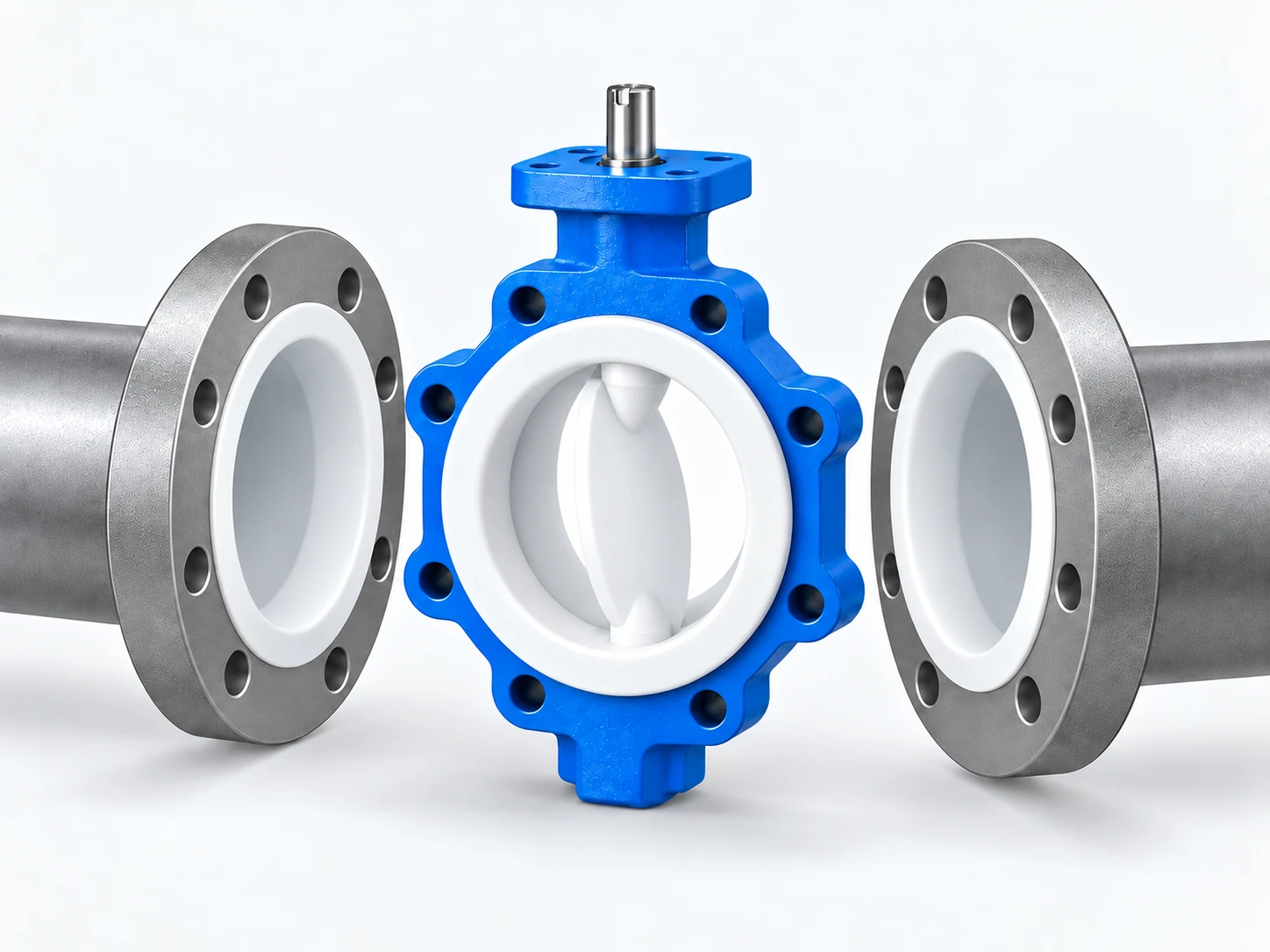
Compact PTFE lined butterfly valve between matching lined pipe flanges, showing the lining faces and partially open encapsulated disc.
01 Flange Bore (ID)
02 Disc Opening Arc
03 PTFE Flange Flare
04 Actuation Interface

Mating Flange ID & Disc Clearance

Prior to bolting wafer or lug valves, pipe engineers must verify the inner diameter of mating pipe flanges. The PTFE encapsulated disc swings into adjacent pipe bore, requiring unhindered clearance to eliminate mechanical contact or lining scoring.

Flange ID Disc Clearance Connection Alignment

Liner Flare Clamping Control

The PTFE flare over the valve flange acts as the primary raised gasket face. Bolts must be torqued progressively in cross-pattern sequences with strictly parallel flange alignment to prevent cold flow over-compression and liner wall pinching.

Flange Parallelism Uniform Torque Liner Protection

Torque-Matched Actuator Sizing

Configured with hand levers, manual worm gears, double-acting / spring-return pneumatic actuators, or modulating electric motors. Actuator torque must be calculated from peak shutoff differential pressure (ΔP) and fluoropolymer break-away torque safety margins.

Closing ΔP Operating Torque Actuation Package

* Lug type installations require confirmation of tapped bolt hole depth, engagement thread length, and full dead-end pressure ratings per approved project GA drawings.

Need bolt torque tables and dimensional installation guidelines for your piping crew?

Download Piping Installation Manual

Engineered for Batching, Dosing & CIP Circuits

Continuous PTFE wetted isolation delivers reliable fluid barrier control across chemical batching skids, precision metering injection lines, and aggressive industrial cleaning systems—installed reliably at tank bottoms, pump manifolds, and bypass loops.

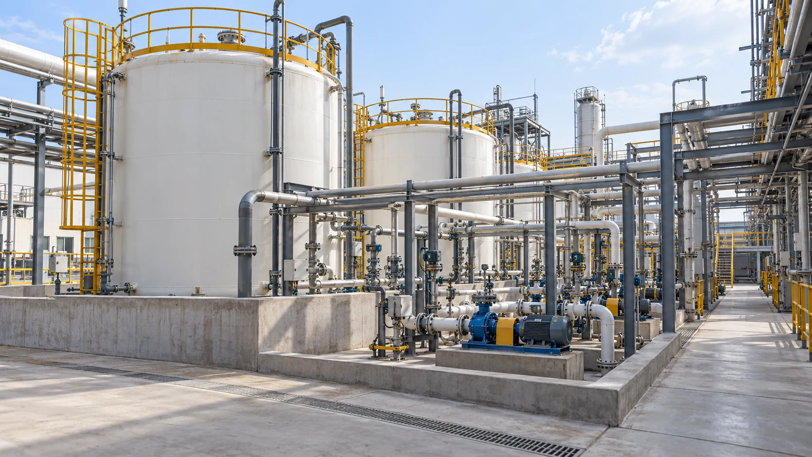
Chemical batching area with closed reactor vessels, mixing equipment, pumps, and supported process pipework.

Chemical Batching Systems

Controls high-purity chemical reagent dilution, reactor vessel transfer, and corrosive mixing streams, enabling repeatable quarter-turn isolation during recipe switching and process line containment.

Typical Valve Locations
  • Batching Tank Outlets
  • Mixing Skid Headers
  • Transfer Pump In/Out
  • Process Branch Lines
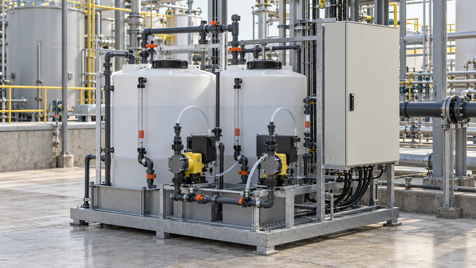
Chemical dosing skid with reagent tanks, metering pumps, corrosion-resistant tubing, and control equipment.

Chemical Dosing Skids

Deploys on automated water treatment injection systems, coagulant pipelines, and disinfectant skid headers where positive zero-leakage shutoff defends against hazardous metering chemical leakage.

Typical Valve Locations
  • Day Tank Drain Ports
  • Metering Pump Suction
  • Dosing Skid Headers
  • Injection Quill Feeds
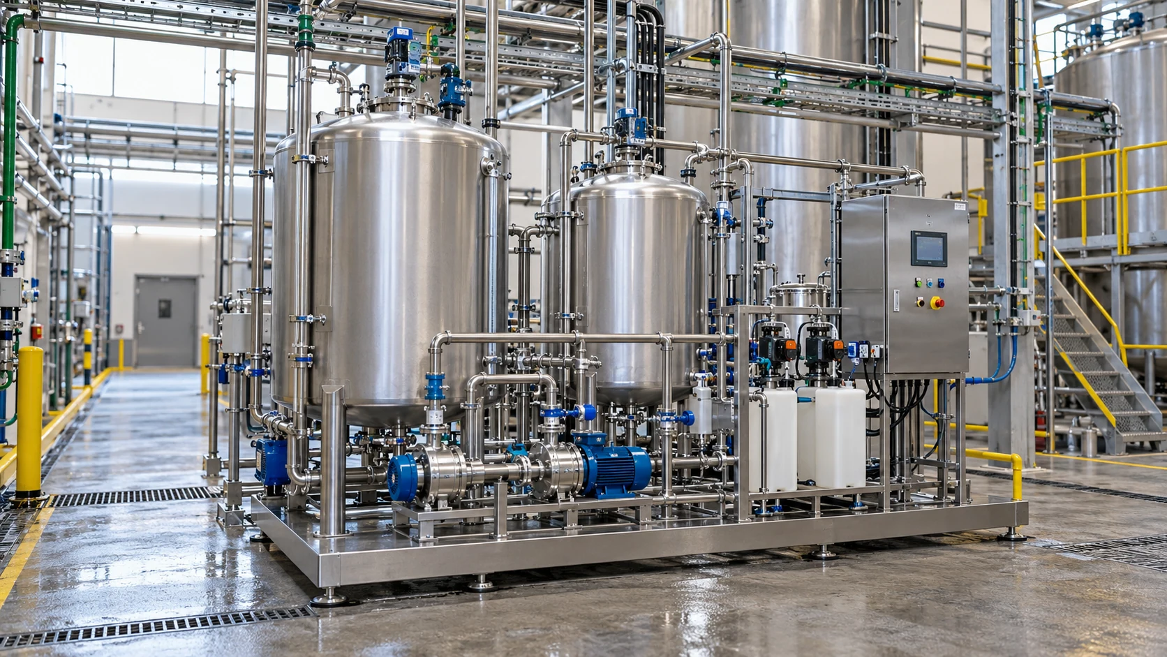
Industrial cleaning and chemical circulation skid with stainless tanks, pumps, dosing equipment, and organized pipework.

Industrial Cleaning (CIP)

Handles cyclical caustic washes, nitric/phosphoric acid rinses, and hot sanitizing flush fluids up to 130°C, providing long-term elastomer-protected wetted isolation without internal elastomer swelling.

Typical Valve Locations
  • CIP Tank Return Manifolds
  • Circulation Pump Loops
  • Heat Exchanger Ports
  • Flush Drain Isolation

Typical Process Installation Sequence

Chemical Storage / Batch Vessel
Transfer / Dosing Pump Skid
Process Reaction Pipeline

Exact valve installation placement must be reconciled against fluid flow direction, pipeline hydraulic water hammer limits, fail-safe actuator configuration, and plant P&ID control philosophy.

Planning a chemical skid installation or retrofitting existing process lines?

Consult Chemical Skid Application Engineer
PTFE Lined Butterfly Valve | Module 11 Acid & Alkali Service

Engineered Isolation for Acid and Alkali Fluid Circuits

Aggressive acidic and basic process media impose distinct chemical attack mechanisms. Our fluoropolymer-lined butterfly valve assemblies provide verified molecular barriers tailored to withstand caustic embrittlement, halogen vapor permeation, and extreme thermal cycling.

Caustic preparation and transfer area with closed storage tanks, chemical transfer pumps, contained working areas, and process piping.

Caustic Soda (NaOH) Preparation & Transfer

Alkaline service requires robust disc encapsulation and zero-void virgin PTFE to prevent stress cracking and chemical erosion in high-concentration sodium hydroxide circuits up to 50% NaOH.

Typical Service Locations

  • Bulk Storage Tank Outlets
  • Chemical Dosing & Metering Headers
  • Transfer Pump Suction & Discharge
Engineering Parameter: Configuration demands concurrent validation of virgin PTFE lining, elastomer energizers, and trace surfactant chemistry.
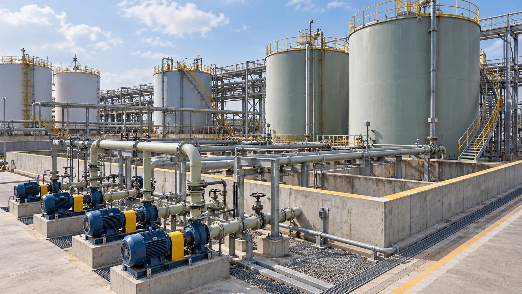
Chemical storage and acid transfer facility with bunded tanks, pump stations, lined process pipes, and accessible service areas.

Acid (HCl & H2SO4) Transfer & Isolation

Hydrochloric and concentrated sulfuric acids demand thick-walled fluoropolymer barriers that resist gas micro-permeation, galvanic body corrosion, and localized pitting at thermal boundaries.

Typical Service Locations

  • Acid Offloading & Containment Skids
  • Reactor Feed Isolation
  • Pickling & Etching Header Lines
Engineering Parameter: HCl and H2SO4 require independent BOM verification; halogen vapor permeation protocols differ from generic chemical ratings.

Verify valve materials and lining thickness for your specific acid/alkali duty:

Consult Chemical Application Specialist
PTFE Lined Butterfly Valve | Module 12 Lining Integrity Inspection

Comprehensive Quality Verification of All Wetted PTFE Surfaces

Total containment reliability requires non-destructive verification before valve release. Every PTFE-lined component is tested against strict mechanical and electrical standards to guarantee an impervious chemical barrier. Review RUITO's manufacturing and quality capabilities when qualifying the lining supplier.

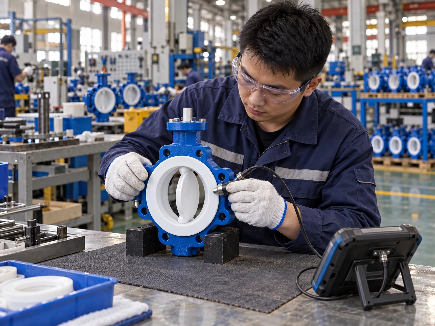
Technician checking the white PTFE lining of a butterfly valve with inspection equipment in an operating valve manufacturing workshop.

Liner Thickness Verification

Non-destructive multi-point ultrasonic gauge mapping across the wetted body bore, disc edges, and neck contours ensures strict conformance to nominal wall thickness design limits.

Design thickness 2-5 mm Local minimum thickness per GA Critical contour uniformity

High-Voltage Spark Testing

100% electrostatic probe sweep across all wetted PTFE surfaces detects micro-cracks, pinholes, and internal voids through calibrated non-destructive dielectric discharge testing.

Seamless barrier verification Microscopic pinhole detection Test voltage calibrated to liner thickness

Flange Flare Seal Inspection

Optical and tactile inspection of the molded flare face confirms smooth transition radiuses, defect-free raised sealing surfaces, and proper compression contact geometry.

Flare integrity Zero surface scoring Uniform raised gasket face

Stem Dynamic Seal & Boundary Inspection

Geometric verification of the disc hub sealing collar and stem entry envelope ensures uniform pre-load against backing energizers for zero fugitive leakage under rotational stress.

Bi-directional shutoff contact Stem entry boundary Zero fluid creep transition

Download complete quality control and testing inspection procedures:

Request QA & Inspection Procedures
PTFE Lined Butterfly Valve | Module 13 Testing & Acceptance

Hydrostatic Integrity & Comprehensive Quality Acceptance

Validation of PTFE Lined Butterfly Valves extends far beyond generic casing pressure retention. Acceptance requires coordinated verification of bubble-tight seat shutoff, rotational actuator response, and specialized fluoropolymer lining integrity. Test hydro pressures represent design qualification thresholds and must never be interpreted as permissible continuous service limits.

Hydrostatic Shell Test

15 bar
PN10 Ambient Hydrostatic Rating

Rigorous hydrostatic overpressure verifies primary ductile iron or stainless body structural containment and flange connection boundaries, confirming zero structural deformation or external wall seepage.

Soft Seat Closure Test

11 bar
PN10 Bi-Directional Shutoff

Bi-directional pneumatic and hydrostatic differential pressure verification tests the resilient seat contact between disc edge and molded liner, validating Rate A bubble-tight isolation according to EN 12266-1.

PTFE Lining Special Audit

Integrity Check
Non-Destructive Dielectric Sweep

Supplementary fluoropolymer audit protocols mandate 100% dielectric spark testing and ultrasonic thickness profiling across wetted faces to eliminate microscopic pinhole risks prior to factory release.

Design & Testing Codes

EN 593 Conformance

Establishes baseline face-to-face dimensions, structural casting thickness, and mechanical drive interfaces for industrial butterfly valves.

EN 12266-1 Hydrostatic Testing

Mandatory baseline inspection code governing shell strength, seat leak rate limits, and hydrostatic hold-duration thresholds.

ISO 5208 Pressure Testing

Provides standardized international test protocols and Rate A zero-leakage closure parameters for lined quarter-turn assemblies.

Approved GA & Inspection Procedures

Project-specific General Arrangement drawings, client specifications, and lining thickness sign-offs govern individual order execution.

Quality Records & Traceability

Serialized Test Correspondence

Every individual valve body and lining assembly links to traceable test dossiers, ensuring complete verification through manufacturing heats.

Certified Test Medium & Conditions

Test logs document water temperature, hold durations, and test pressures, preventing conflation between test parameters and operating ratings.

Configuration-Specific Sign-Off

Each diameter, fluoropolymer compound, and seat energizer is verified against its distinct BOM matrix without cross-configuration extrapolation.

EN 10204 3.1 Material Certification

Supplied with complete mill certificates and quality dossiers detailing chemical analysis, tensile testing, and spark inspection records.

Need inspection test plans (ITP) or factory acceptance testing (FAT) procedures?

Download Factory Inspection Protocols
PTFE Lined Butterfly Valve | Module 14 Engineering Selection

Precise Valve Sizing Guided by Operating Parameters

Selecting a PTFE Lined Butterfly Valve requires rigorous parameters beyond nominal diameter (DN), pressure rating (PN), or generic "acid resistant" descriptions. Fluid chemistry, operational temperatures, differential pressures, connection styles, and cycle frequencies must be validated concurrently to finalize exact BOM specifications.

Input 01

Chemical Fluid Composition

Parameters Required
Exact chemical nomenclature, aqueous solution components, and solvent blends.

Beyond primary media, specifiers must declare dissolved trace gases, entrained abrasive crystals, organic surfactants, or cyclical cleaning additives that affect fluoropolymer permeation.

Input 02

Media Concentration Thresholds

Parameters Required
Nominal mass fraction (w/w %), specific gravity, and anticipated concentration shifts.

Liner barrier resistance varies dramatically between dilute and concentrated phases. Broad descriptions such as "acidic water" or "caustic waste" are insufficient for engineering sign-off.

Input 03

Operating Thermal Boundaries

Parameters Required
Continuous operating temperature, minimum winter startup, and maximum wash peak.

Thermal cycles dictate fluoropolymer expansion rates, elastomeric energizer selection (Silicone vs FKM), and allowable system pressures; ambient temperatures cannot substitute fluid limits.

Input 04

Line Pressure & Closing ΔP

Parameters Required
Normal working pressure, surge potentials, and maximum shutoff differential (ΔP).

Working line pressure validates body containment limits, while break-away differential pressure directly governs shaft torsion sizing and required actuator torque output margins.

Input 05

Nominal Size & End Connections

Parameters Required
DN25–DN300 bore, Wafer vs Full-Lug body, and mating flange drilling standards.

Requires geometric confirmation of adjacent pipe internal bore clearance, ensuring unobstructed disc swing and zero liner flare pinching during bolt tensioning.

Input 06

Actuation & Project Controls

Parameters Required
Manual lever/gear, pneumatic double-acting/spring-return, electric modulating.

Sized to operating cycle frequency, fail-safe requirements, hazardous area certifications (ATEX/IECEx), and mandatory project documentation deliverables (GA / 3.1 MTR).

Engineered Valve Sizing & Verification Protocol

Duty Input Media, conc., temp., pressure
Wetted Trim Matching PTFE liner, disc, energizer
PT Limits Verification Coupled boundary derating
Drive Integration Torque margin & connection
BOM & GA Approval Certified project documentation

Engineering Rule: Peak ratings across unrelated BOM lines must never be combined. Final configuration approval is grounded exclusively in the unified co-existence of temperature, fluid chemistry, pressure boundary, and approved GA dimensional clearance.

Have a specific chemical line specification ready for engineering review?

Submit Pipeline Operating Conditions
PTFE Lined Butterfly Valve | Module 15 Sizing & RFQ Inquiry
Wide chemical process facility view with reactor vessels, pipe racks, and an organized transfer area.
Engineering Selection & Inquiry

Obtain Tailored PTFE Lined Butterfly Valve Proposals for Your Chemical Service

Submit your fundamental operating parameters. Our fluid application engineers will reconcile media chemistry, thermal cycles, and closing differential pressure to formulate the optimal PTFE Lined Butterfly Valve configuration backed by comprehensive technical documentation and project quotations.

Sized strictly against specific chemical media composition & fluid concentration
Verified virgin PTFE wetted lining integrity and encapsulated disc geometry
Wafer and Full-Lug body options matching ANSI 150# / DIN PN10/16 flanges
Torque-matched manual lever, gear operator, pneumatic, or electric automation
Complete project engineering submittals: GA drawings, BOM, and 3.1 MTR dossiers
Isolated RFQ Form
Isolated RFQ Form
Isolated RFQ Form

Request Sizing & Quotation

Provide your baseline parameters; an application specialist will contact you with a verified proposal.

Upon submission, our technical team will review your chemical fluid data, design envelope, and delivery schedule within 24 hours.

Why Choose RUITO for Your Industrial Valve Solutions?

Get expert technical consultation and discover how our precision-engineered valves can optimize your industrial operations.

ISO 9001, CE, WRAS & DNV Certified
All products meet European and international standards with comprehensive certifications for critical applications.
24-Hour Technical Response Guarantee
Our experienced engineering team provides technical consultation and design solutions within 24 hours.
Fast Delivery & Flexible MOQ
Stock products ship in 5 days, custom solutions in 15-25 days. Minimum order just 10 units.
Custom Engineering Solutions
From standard products to complex custom designs, our R&D team creates solutions for your specific requirements.
99.5% Quality Reliability
Rigorous 6-step quality control process with 12-month warranty and 100% pressure testing on all products.
Global Export Experience
Successfully serving 150+ clients across Europe, North America, and Asia with full English documentation support.

Get Your Free Technical Consultation

Connect with our valve experts and receive personalized solutions for your industrial projects. No commitment required.

Submission issue? You can also contact us directly: