
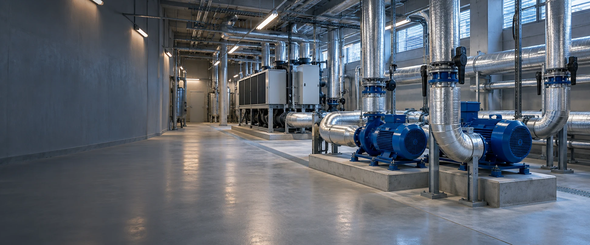
Wafer Butterfly Valve: Compact, High-Integrity Pipeline Isolation
Engineered for water utility, HVAC circulation, and industrial plant systems. Custom-configured across media compatibility, pressure ratings, and automated actuation to deliver leak-free pipeline security.
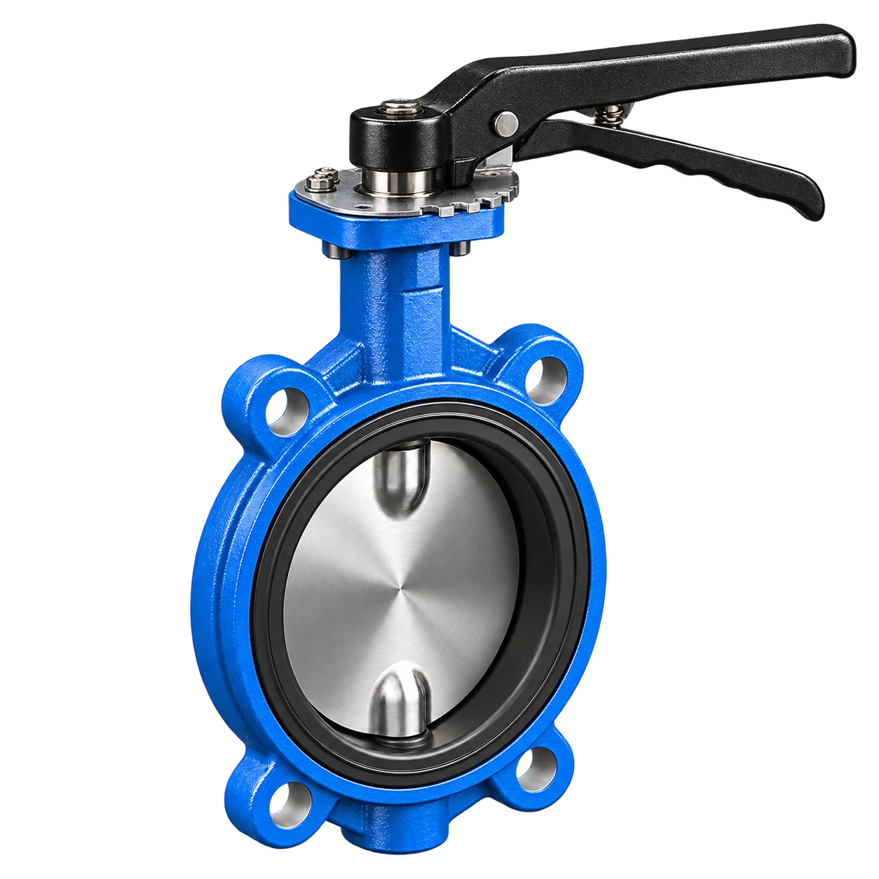
Compact Inter-Flange Architecture for Dependable Flow Isolation
A Wafer Butterfly Valve is engineered to be clamped directly between two companion pipe flanges, utilizing a centered disc rotation to achieve immediate on/off isolation and flow regulation.
Its streamlined body geometry drastically cuts down installation footprint and overall pipeline weight, making it an optimal choice for potable water, industrial cooling circuits, and approved process media. Every assembly is precision-matched with disc, seat, and stem metallurgy to assure total compatibility under rigorous working conditions. To compare body styles and application options, explore our butterfly valve range.
Compact Wafer Architecture
Fits tightly between matching flanges, cutting installation length and spatial footprint.
Rapid 90° Actuation
Quarter-turn rotation ensures fast opening and positive shut-off for time-critical isolation.
Multi-Media Compatibility
Configurable with tailored elastomers and disc alloys for clean water, glycols, and light oils.
Diverse Operating Options
Readily configured with lever handle, worm gear, electric actuator, or pneumatic drive.
Need certified dimensions or CAD drawings for your project layout?
Download Technical DatasheetCompact Installation, Direct Operation, and Precise Application Fit
Wafer Butterfly Valves leverage an ultra-short face-to-face inter-flange footprint and 90° quarter-turn rotation to drastically minimize piping space, while tailoring metallurgy and elastomer seals to specific media, thermal, and differential pressure conditions.
Compact Installation
Clamped smoothly between companion flanges, drastically shortening structural length without compromising pipeline isolation safety. If the project requires separate flange bolts on each side of the body, compare our lug butterfly valves.
- Ideal for spatial-constrained plant rooms & skids
- Drastically cuts overall valve mass & pipe load
- Flange ID verified for 100% full-disc swing clearance
90° Rapid Actuation
Quarter-turn disc travel delivers instantaneous open/close cycles, empowering swift local manual emergency intervention or seamless SCADA automation.
- Quarter-turn full stroke for immediate isolation
- Standardized 10-position throttle notch plate
- ISO 5211 top flange for electric/pneumatic direct-mount
Engineered-to-Condition
Matched components prevent premature wear, avoiding one-size-fits-all compromises across complex chemical and thermal envelopes.
- Potable water & glycol chilled circuits (EPDM)
- High-flashpoint mineral & lubricating oils (NBR)
- Clean instrument compressed air & nitrogen systems
Need assistance evaluating space constraints or flow calculations?
Consult Engineering SpecialistEngineered for Industrial Equipment & Infrastructure Pipelines
From municipal drinking distribution to industrial cooling towers, process recycling, and oil skids, Wafer Butterfly Valves provide dependable shut-off and long-term isolation customized to fluid dynamics and site specifications.
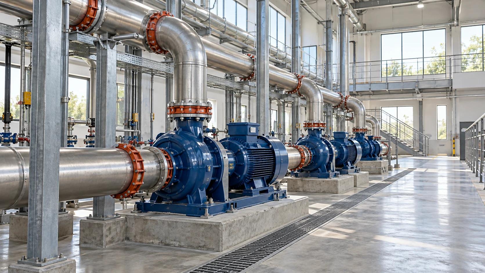
Municipal & Building Water Supply
Reliable on/off isolation for potable supply mains, commercial booster pump rooms, and clean water plant networks with optimized flow coefficient.
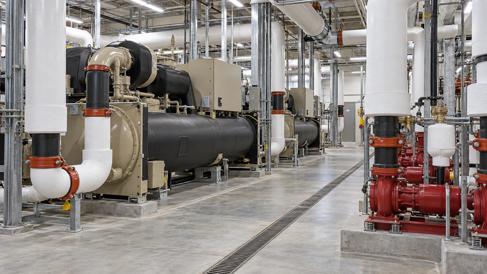
HVAC & Cooling Circulation
Designed for commercial chillers, cooling towers, and closed-loop hydronic circuits requiring low pressure drop and bubble-tight isolation.
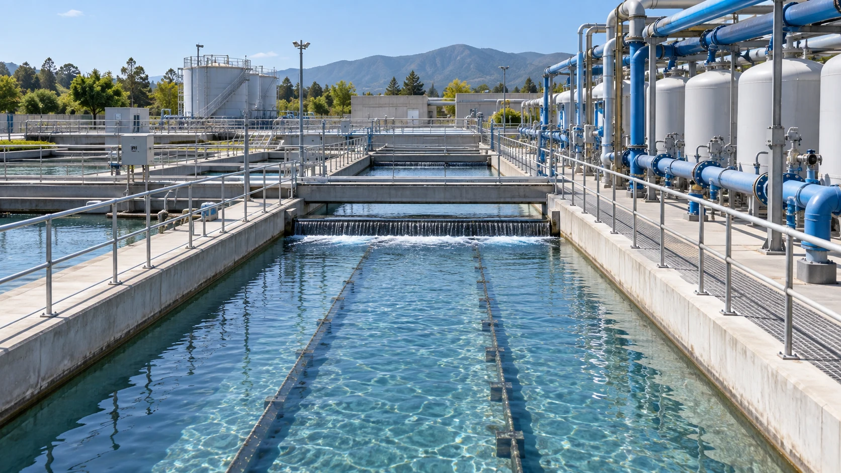
Treated & Recycled Water
Suited for secondary filtration units, clarified wastewater pipelines, and industrial water recycling manifolds with non-abrasive characteristics.
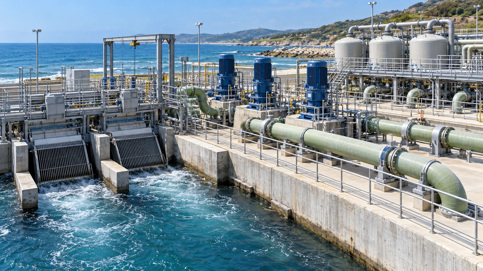
Seawater Intake & Pre-Treatment
Configured with corrosion-resistant nickel aluminum bronze disc and marine elastomers for coastal low-pressure screening and intake manifolds.
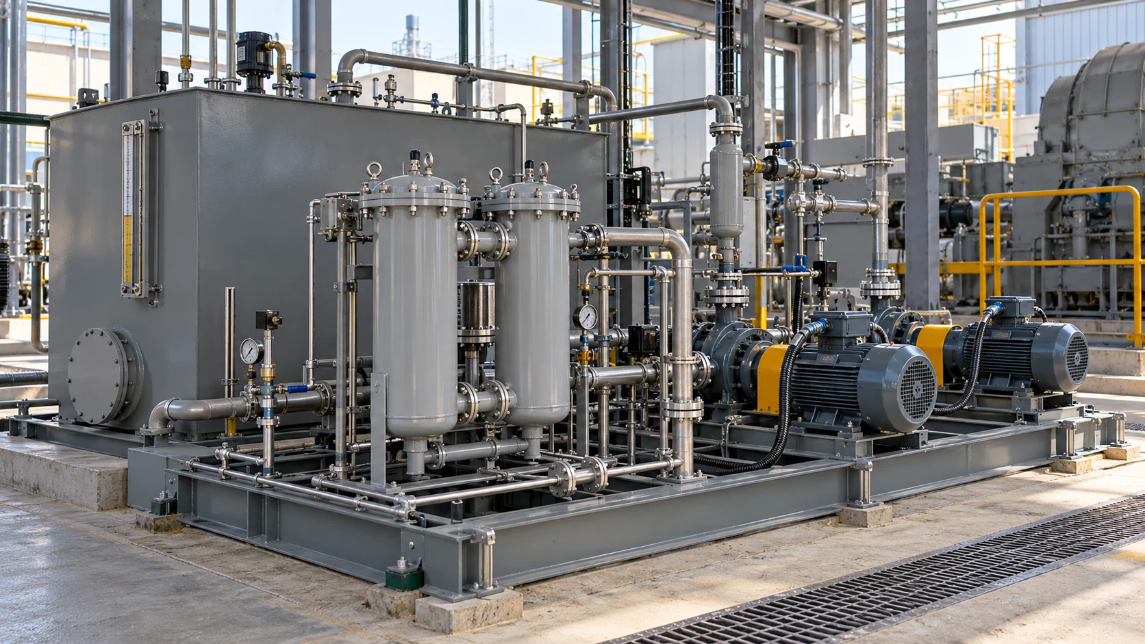
Industrial Mineral Oil Piping
Equipped with oil-resistant NBR elastomeric liners for heavy machinery lubrication loops, gear oil headers, and auxiliary fluid transfer skid systems.
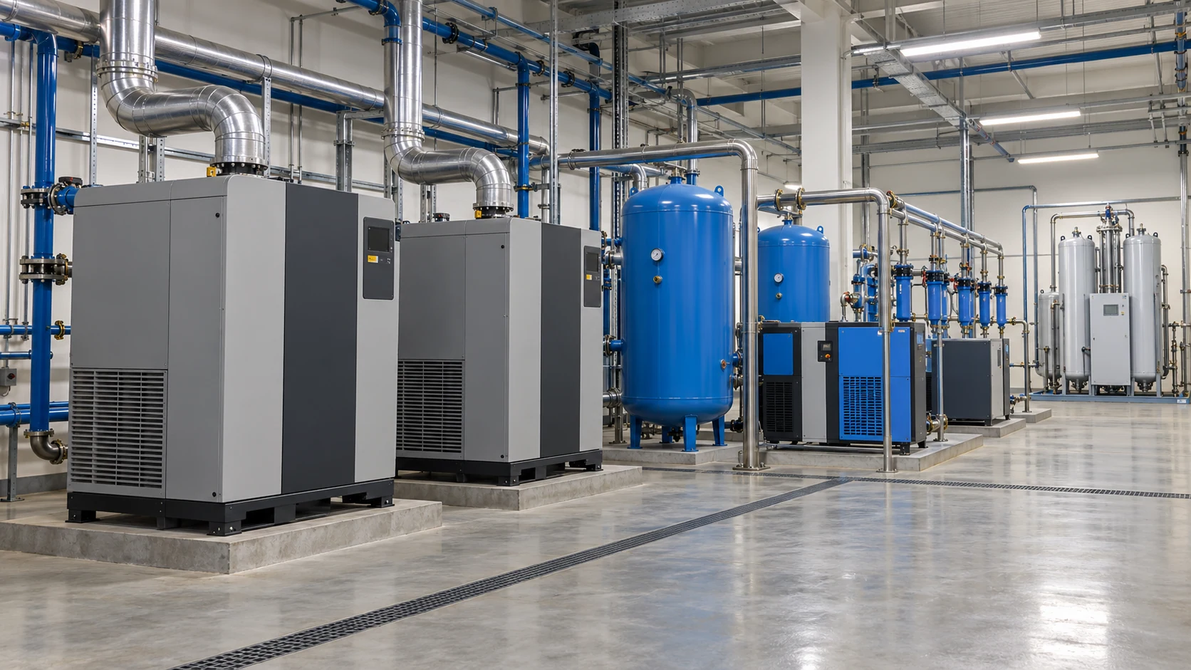
Compressed Air & Nitrogen Systems
Clean air and inert gas package delivering certified tight stem sealing and swift quarter-turn response for compressor rooms and distribution banks.
Looking for tailored valve configurations for specific application media?
Request Application SizingTailoring Metallurgy and Sealing Architecture to Pipeline Fluid Dynamics
The application boundaries of a Wafer Butterfly Valve cannot be determined by valve nominal rating alone. Fluid composition, concentration, operating temperature, differential shut-off pressure, and elastomeric resistance must be harmonized as a single unified specification to prevent cross-condition failure.
Clean & Potable Process Water
5°C to 60°C | PN10 / PN16 according to actual P-T boundary
Ductile Iron GJS-500 body, CF8M Stainless Disc, Resilient EPDM Liner
Working pressure is constrained by temperature, shut-off differential, and mating flange rating.
Glycol Chilled Circuits
0–40% Glycol (5°C to 60°C, ≤10 barg). Low-temp package extends to 40–45% (-10°C to 60°C, freeze point ≤-20°C).
Enhanced water trim, high-grade EPDM, low-temp sub-zero package
Requires chemical verification of corrosion inhibitors, pH levels, and actual fluid viscosity.
Compatible Mineral Oils
5°C to 70°C | Working Pressure ≤10 barg
Dedicated petroleum-rated trim, resilient NBR seat, reinforced nitrile secondary stem seals
Aromatic hydrocarbon content and oil additives must be verified; standard EPDM will swell and degrade rapidly in petroleum.
Clean Compressed Air & Nitrogen
5°C to 40°C | Working Pressure ≤6 barg
Clean gas degreased seal trim, certified bubble-tight resilient liner & stem sealing
Dedicated to non-combustible clean gases; does NOT automatically qualify for natural gas or fuel hydrocarbons.
Seawater & Marine Cooling
5°C to 40°C | Working Pressure ≤10 barg
Wetted components in Nickel Aluminum Bronze (ASTM B148 C95800) or corrosion-reviewed super duplex alloy
Velocity limits, chlorination dosing, crevice and galvanic corrosion must be audited; not for high-pressure RO membrane sections.
Uncertain about your process medium's chemical concentration or corrosion rate?
Request Media Compatibility ReviewCritical Component Metallurgy Harmonized for Reliable Longevity
The valve body, disc, resilient seat, and central stem function collectively as an integrated pressure-containment and flow-isolation system. Material selection must satisfy mechanical stresses, chemical compatibility, and thermal resilience simultaneously.
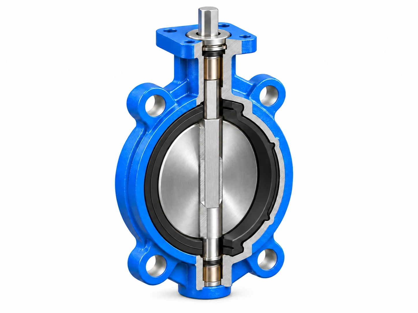
Valve Body
Primary pressure boundary & piping structural support. Ductile Iron EN-GJS-450-10 / GJS-500-7 with protective fusion-bonded epoxy coating.
Pressure Class / Thermal Range / Ambient ExposureDisc
Directly immersed in flow path. Precision-profiled CF8M (316 SS) for clean water, or C95800 Aluminum Bronze for marine salinity.
Corrosive Media / Velocity Limits / Dynamic Seat SealingResilient Seat
Determines bubble-tight zero-leakage shut-off. Molded EPDM for water & glycols; dedicated oil-resistant NBR for petroleum loops.
Chemical Compatibility / Shore Hardness / Compression SetStem / Shaft
High-strength one-piece or two-piece 316/410 SS shaft engineered to transmit full operational actuator torque without twisting.
Actuator Torque / Shear Strength / Zero-Blowout StemIdentical Material Nomenclature Does Not Guarantee Identical Application Suitability
Elastomer formulation, polymer cure grade, mating metallurgy, nominal diameter, and mechanical differential pressure must all align in a single verified configuration. Field component substitution requires comprehensive engineering validation. For chemically aggressive duties requiring a fluoropolymer barrier, review PTFE-lined butterfly valves with application-specific compatibility checks.
Looking for tailored material certification (EN 10204 3.1) or custom trim packages?
Configure Custom MaterialsHarmonizing Pressure Ratings with Thermal Operating Boundaries
A Wafer Butterfly Valve's operational capacity is governed as an integrated system across body metallurgy, disc profile, elastomer liner, and flange mating. Nominal PN designations indicate static cold ratings; allowable operating pressure must always be verified against the dynamic P–T curve rather than combining maximum temperature with maximum pressure.
DN50–DN600
Standard Manufacturing Range - Tailored trims, torque calculations, and differential shut-off verified per bore size.
PN10 / PN16
Nominal Design Ratings - Cold water limits of 10 barg and 16 barg; requires derating along thermal boundaries.
0°C to 80°C
Standard Trim Thermal Range - Typical 5°C to 60°C in clean water; sub-zero packages extend to -10°C to 60°C.
Final permissible operating boundaries subject to validated elastomer compound, disc metallurgy, and site engineering specifications.
Require thermal derating verification or high-pressure differential calculations?
Request P-T Engineering ReviewPrecision Flange Alignment & Unobstructed Disc Travel
Because wafer valves lack integral pipe flanges, secure isolation relies entirely on correct inter-flange clamping, axial concentricity, and full internal clearance for quarter-turn disc articulation. Where the specification calls for a valve body with integral end flanges, compare flanged butterfly valves instead.
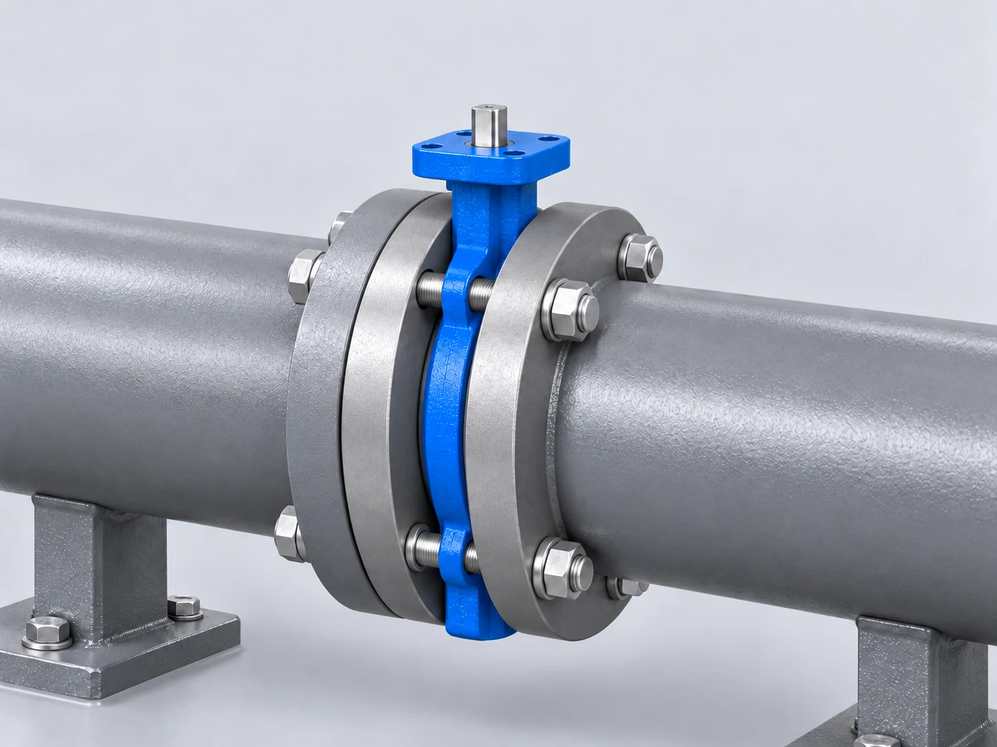
Verify Companion Flanges
Inspect flange standard, schedule, and internal diameter to ensure smooth face mating and eliminate disc impingement.
Assure Internal Disc Clearance
Confirm pipe bore exceeds disc chord extension before torquing to avoid rim scoring or elastomer pinch.
Maintain Concentric Piping Alignment
Center valve body precisely along pipe centerline to balance compression stress across resilient seat faces.
Cross-Pattern Bolt Torquing
Tighten stud bolts incrementally in a cross-diagonal sequence to achieve uniform face seal loading without flange deformation.
Flange Standard / Concentric Alignment / Disc Articulation Clearance: Never determine compatibility by nominal DN alone. Verify actual companion pipe schedule and inner bore dimensions prior to tightening.
Need installation manuals, bolt torque schedules, or CAD drawings for your piping designers?
Download Installation GuidelinesReliable Shut-Off Engineered Through Precision Disc-to-Seat Geometry
Wafer Butterfly Valves employ a resilient interference-fit elastomeric seat geometry, achieving bidirectional zero-leakage isolation. Reliable sealing integrity depends on harmonious coordination between elastomer compound resilience, operating delta P, and matched seating torque.
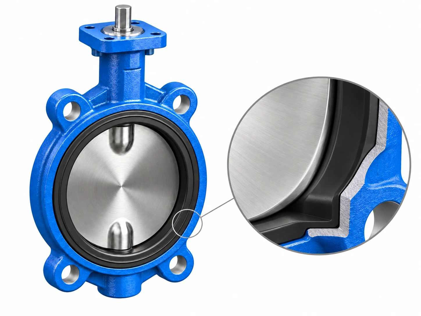
Resilient Disc-to-Seat Sealing Interface
CAD cross-sectional profile illustrating interference band compression, elastomer displacement gradient, and symmetric contact stress distribution across the spherically profiled 316SS disc edge.
Closed State: Continuous Radial Compression Seal
In the fully closed position, the precision spherically machined disc edge compresses into the resilient elastomer seat, establishing an impermeable zero-leakage barrier across maximum operating differential pressure. Uniform 360° seating stress eliminates localized leak paths common in rigid-seated valves.
Open State: Smooth 90° Articulation & Full-Bore Clearance
During rotation, the disc swiftly clears the sealing zone into the pipe flow stream, requiring adequate companion piping clearance and stable torque without elastomer galling. Low break-out friction minimizes wear, preserving long cycle life and elastic recovery of the liner.
Disc & Seat Profiling
Micro-finished disc edge and molded resilient contour balance tight compression with minimal operational friction.
Shut-Off Differential P
Sealing capability is dictated by true pipeline delta P across the closed disc rather than static nominal PN rating.
Elastomer Compound Match
Tailored EPDM, NBR, or specialty polymers prevent thermal hardening, chemical swelling, or compression set.
Actuator Torque Alignment
Sized to exceed break-away, dynamic hydrodynamic, and seat-engagement torques under worst-case pipeline conditions.
Require differential shut-off verification or specific leakage class certificates?
Request Sealing Data & Engineering ReviewVersatile Actuation: From Rapid Manual Control to Integrated Process Automation
Wafer Butterfly Valves feature standardized ISO 5211 direct-mount top flanges, allowing seamless configuration with manual levers, precision worm gearboxes, electric multi-turn motors, or high-speed pneumatic rotary actuators matched to plant automation protocols.
Lever Handle | Manual Control
Compact manual operator for swift quarter-turn isolation
- 90° rapid opening & closing
- 10-position graduated notch throttle plate
- Ideal for accessible manual lines & pump skids
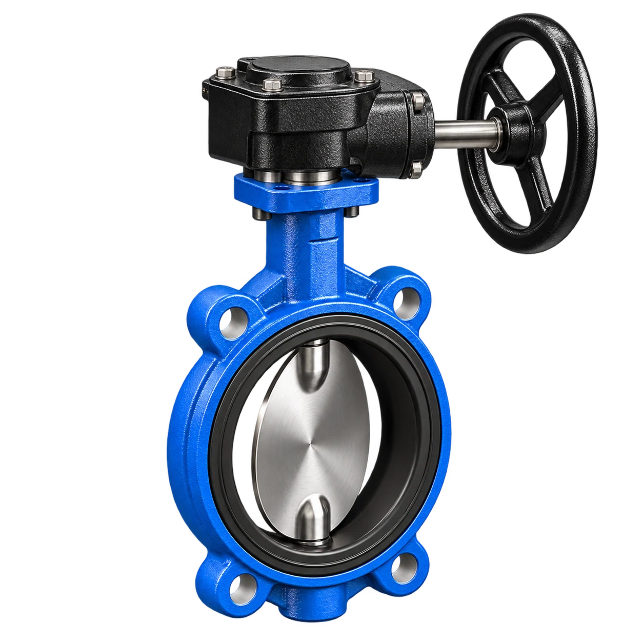
Worm Gear | Manual Gearbox
Mechanical advantage gearbox ensuring low-effort throttling
- Self-locking gear train prevents disc slam
- Cast handwheel with position indicator
- Optimal for larger diameters (≥DN150) & higher ΔP
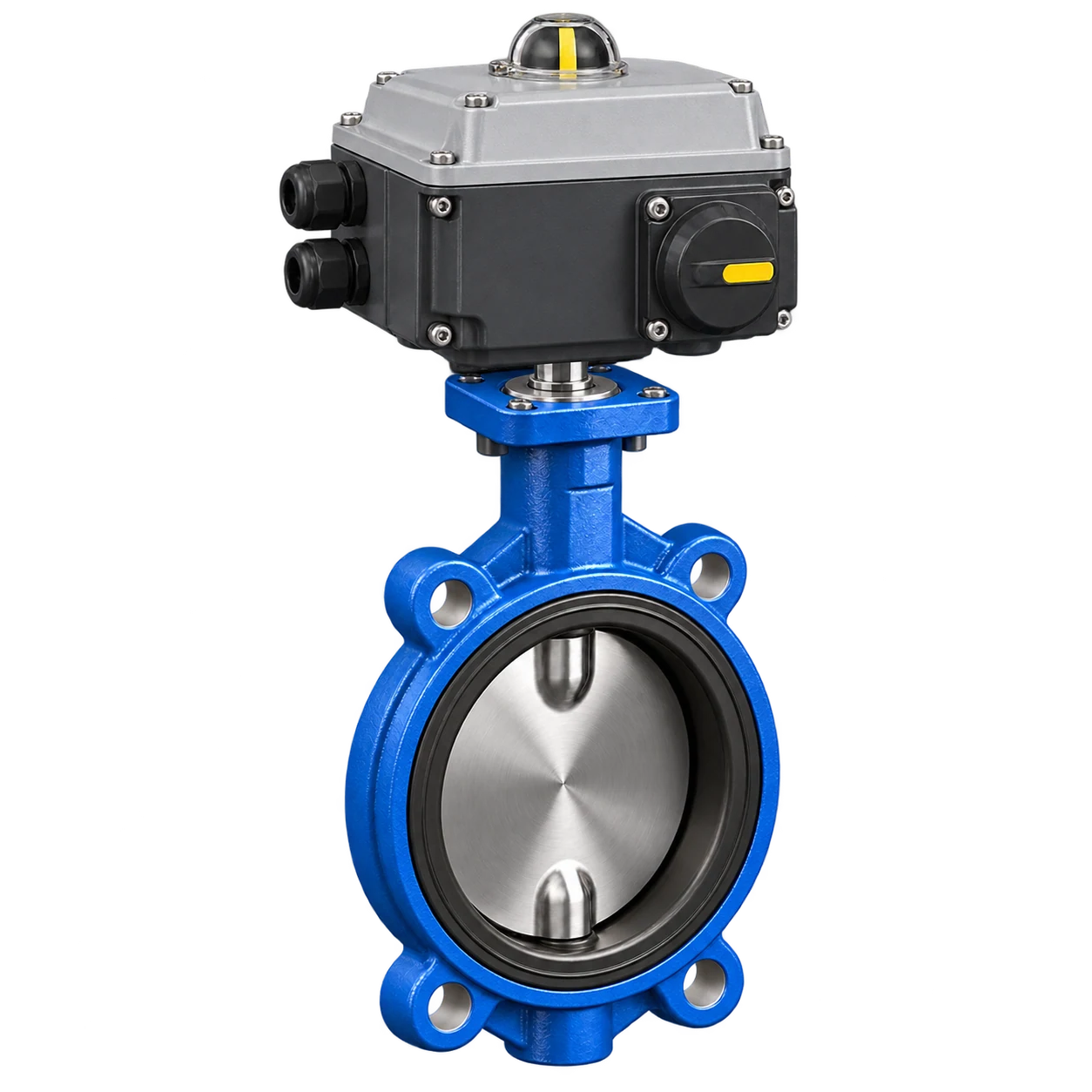
Electric Actuator | Smart Control
Quarter-turn motor drive for automated SCADA integration
- Modulating 4–20mA or on/off control
- Manual override handwheel & local indicator
- Weatherproof enclosure with torque limit switches
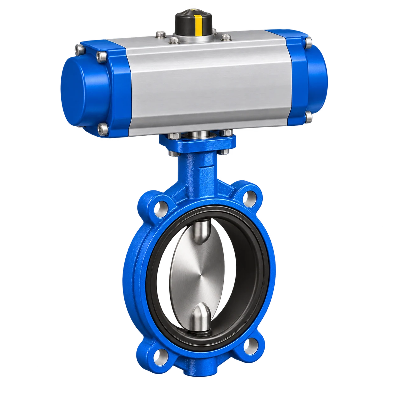
Pneumatic Actuator | High-Speed
Double-acting or spring-return rack & pinion rotary drive
- Rapid cycle speeds for automated batching
- NAMUR solenoid & limit switch box mounting
- Fail-safe spring return (NC/NO) for shutdown
Need automated valve package sizing, wiring schematics, or CAD models?
Configure Actuation PackagePrecision Quality Verification: From Hydrostatic Proof to Bubble-Tight Seat Integrity
Comprehensive inspection protocols validating assembly fit, pressure retention, closure tightness, and mechanical articulation tailored to strict international standards (EN 12266-1 / ISO 5208).
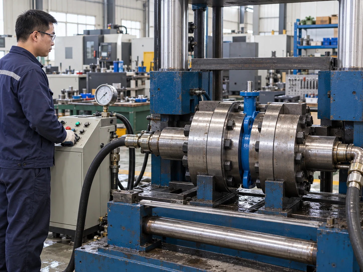
Standardized Test Bench Regimes
Every wafer butterfly valve undergoes individual hydraulic shell and seat containment testing prior to final dispatch. Factory calibration strictly complies with standardized pressure ratings and certified test procedures.
- Continuous gauge calibration referenced against certified master transducers
- Digital dwell-time monitoring to prevent pressure pulse misreadings
- Standardized bidirectional zero-leakage verification (Rate A compliance)
Visual & Dimensional Inspection
Rigorous verification of casting integrity, epoxy coating thickness (DFT), face-to-face conformity to ISO 5752, and precision assembly trim fitment.
Visual status, coating DFT gauge readings, full dimensional report.
Hydrostatic Shell Proof Test
Rigid verification of the primary pressure boundary at 1.5x nominal rating without structural wall deformation or external body sweating.
Recorded: Hold duration, zero external leakage.
Resilient Seat Tightness Test
Differential closure verification achieving bubble-tight zero leakage at 1.1x nominal pressure rating across the disc interface in the flow direction.
Recorded: Flow orientation, zero-bubble confirmation.
Mechanical Articulation & Torque
Full 90° opening and closing stroke cycles executed under differential operational loads, checking consistent stem rotation and seat breakout values.
Breakaway torque, travel clearance, mechanical end-stop limits.
Require certified pressure test reports or third-party inspection witness?
Request Test Procedures & Inspection DataTraceable Technical Documentation Supporting Every Stage from Tender to Commissioning
Controlled technical documentation packages ensuring contractual alignment across engineering design, QA validation, site installation, and plant handover.
Technical Datasheet
Comprehensive engineering parameters, Kv flow characteristic curves, elastomer temperature limits, material grades, and nominal operating boundaries.
General Arrangement (GA) Drawing
Certified dimensional drawings, overall clearance envelopes, net weights, center-of-gravity details, and ISO 5211 top-flange actuator interfaces.
Material Test Reports (MTR / BOM)
EN 10204 3.1 mill test certificates authenticating chemical composition, tensile/yield strengths, and individual foundry melt lot numbers for pressure parts.
Inspection & Test Plan (ITP)
Defined quality hold points, hydrostatic test witness milestones, NDT examination criteria, and customized customer audit requirements.
Installation, Operation & Maintenance
Step-by-step wafer inter-flange bolting torque sequences, disc concentric alignment guidelines, actuator setup protocols, and routine liner replacement manuals.
Manufacturer Data Report (MDR)
Compiled quality dossier combining final pressure inspection charts, paint DFT certs, CE/PED declarations of conformity, and as-built records.
Need CAD models (STEP/DWG), complete technical submittal packages, or custom ITP drafts?
Download Engineering Documentation PackageApproved Sample Architecture Maintained Uncompromised Across Batch Runs
For OEMs, brand partners, and project contractors, engineering success relies not only on first-article prototype qualification, but on guaranteeing that repeat production runs preserve verified metallurgy, seat compression, dimensions, and operational torque without unapproved field drift. Review RUITO's manufacturing and quality capabilities for supplier qualification.
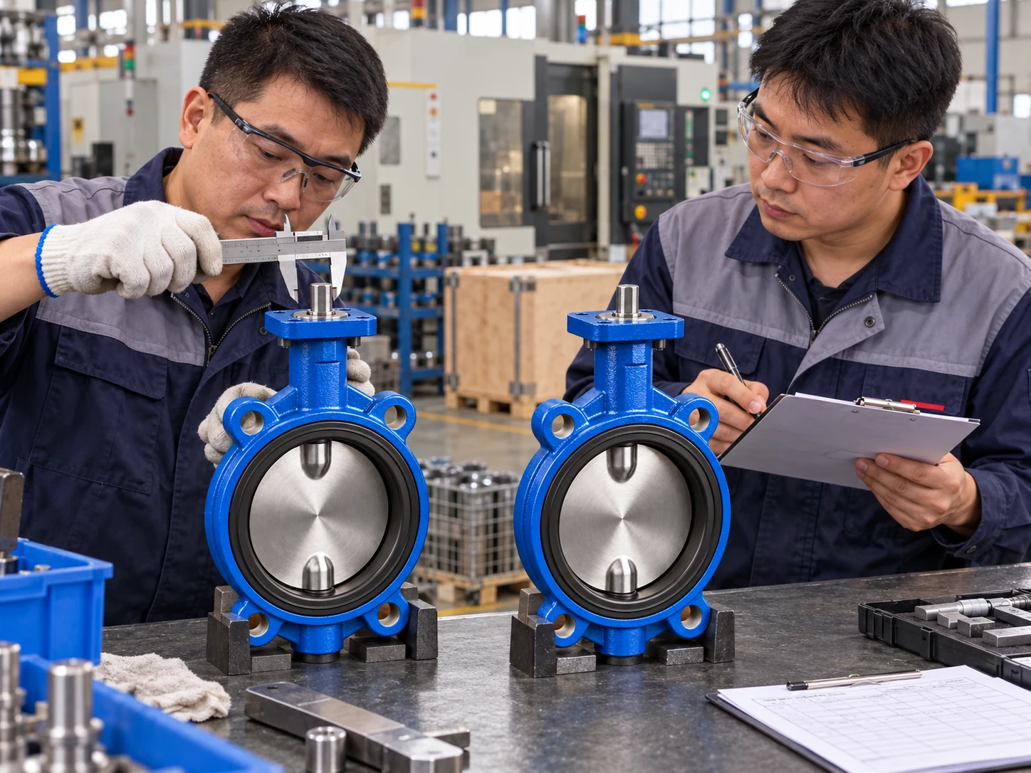
Live Assembly Line Quality Inspection — Zero Specification Drift
First Article & Sample Verification
Prior to mass procurement, prototypes confirm physical dimensions, companion flange fitment, 90° travel, and skid integration.
Controlled Configuration Lock
Freezing verified drawings, elastomer formulations, and bill of materials (BOM) into locked production masters to eliminate unauthorized adjustments.
Batch Production Repeatability
Repeat manufacturing adheres to identical locked masters, assuring uniform casing wall thickness, epoxy DFT, and sealing torque across batches.
Strict Change Governance
Any component, foundry tooling, or trim modification undergoes comprehensive impact audits and client sign-off prior to lot implementation.
Ready to establish a consistent, controlled supply schedule for your project or OEM requirements?
Initiate Sample & Batch Verification ReviewTraceable Milestones from Initial RFQ to Final Plant Dispatch
Wafer Butterfly Valve procurement extends far beyond volume and unit pricing. We integrate engineering qualification, drawing freeze, controlled assembly, hydrostatic witness, and final release into a synchronized protocol ensuring delivered valves strictly fulfill project site conditions.
Submit Project Requirements
Provide core process parameters and purchasing schedule to launch comprehensive engineering evaluation. (Datasheets, valve schedules, or line P&IDs).
Technical Evaluation & Audit
Experienced valve specialists review fluid boundaries and clarify application deviations. Preliminary selection and technical reviews provided within ~2 business days.
Drawing & Trim Lock
Freeze certified GA outlines, face-to-face dimensions, metallurgy, resilient elastomer compounds, and actuation interfaces prior to production.
Controlled Manufacturing & QA
Component casting, machining, assembly, and rigorous hydrostatic shell, seat (Rate A), and torque tests. Customer and third-party witness hold points accommodated.
Inspection Release & Dispatch
Final MDR dossier compilation, export packing, laser tag verification, and logistics coordination with complete heat and batch traceability.
Rapid Technical Response
Typical qualification submittals and preliminary trim recommendations returned in approximately 2 business days upon receipt of complete fluid and pipeline data.
Flexible Volume & Pilot Runs
Standard catalog SKUs available for skid prototyping. Non-stock engineered configurations feature a low standard MOQ of 10 units, with custom qualification samples reviewed per project requirements.
Mature Batch Production Lead Time
Typical fabrication and factory acceptance testing cycle of 30–50 calendar days for standard bore sizes. Final schedule aligns with custom metallurgy, actuator automation, and witness inspection scopes.
Ready to review production schedules or submit your valve schedule for immediate engineering review?
Initiate Order & Delivery Review
Engineered Wafer Butterfly Valve Solutions Tailored to Your System Operating Conditions
Submit your core process parameters or procurement schedule. Our engineering specialists conduct a preliminary technical evaluation to deliver accurate valve trim sizing, certified submittal datasheets, and direct manufacturer pricing.
Configured to Exact Site Dynamics
Precise alignment across fluid medium, P–T boundary envelopes, flange standard, and shut-off differential.
Technical Sizing & GA Drawing Support
Comprehensive engineering packages including certified 2D GA drawings, 3D STEP models, and Kv calculations.
Prototype Qualification & Volume Batches
Agile pilot run verification for skid builders, OEM integration, and structured multi-year delivery contracts.
Full Heat & Hydrostatic Traceability
Laser-etched serial tags permanently linked to EN 10204 3.1 mill certs and hydraulic test logs.
Complete Project Dossier Delivery
Compliant project documentation dossiers accommodating ITP hold points, IOM manuals, and MDR handover books.
Request a Quote
Share your basic project requirements; our application engineers will confirm operating specifics.