
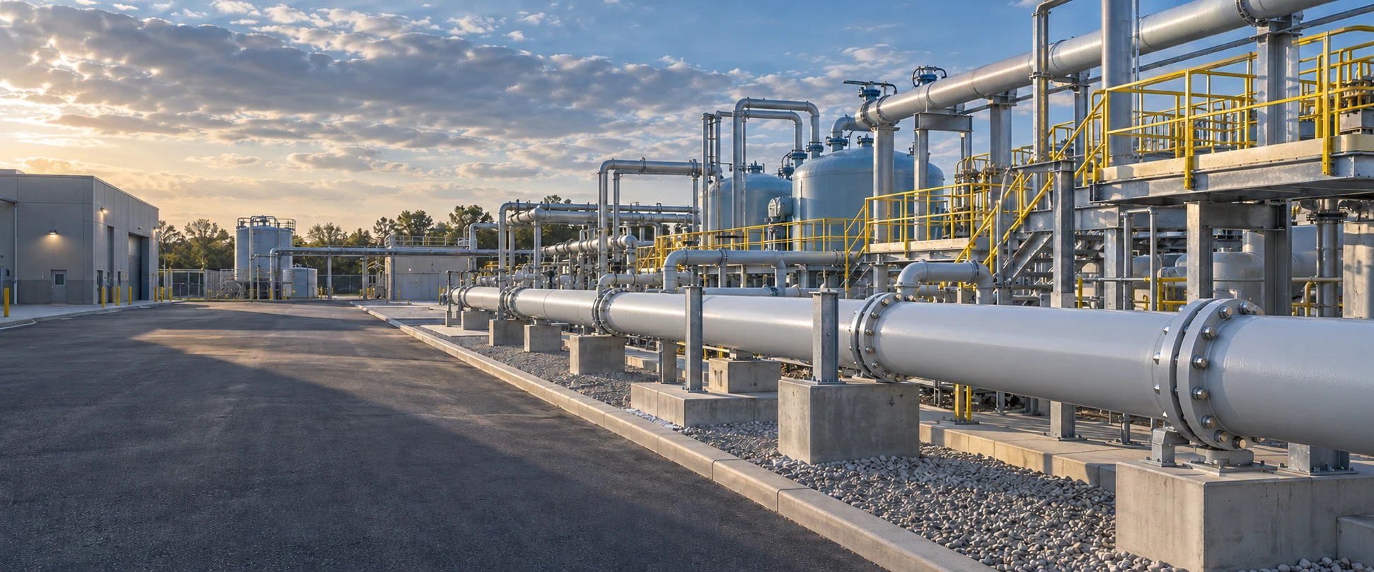
Engineered Lug Butterfly Valves for Reliable Industrial Pipeline Isolation & Regulation
Featuring a heavy-duty threaded lugged body with precision-machined disc and elastomer seating, our valves provide bubble-tight shut-off and long service life across water treatment, HVAC circulation, and industrial fluid systems.
What is a Lug Butterfly Valve?
A compact rotary valve engineered with independent threaded lug connections on the perimeter, purpose-built for dependable isolation and flow control in industrial pressure piping.
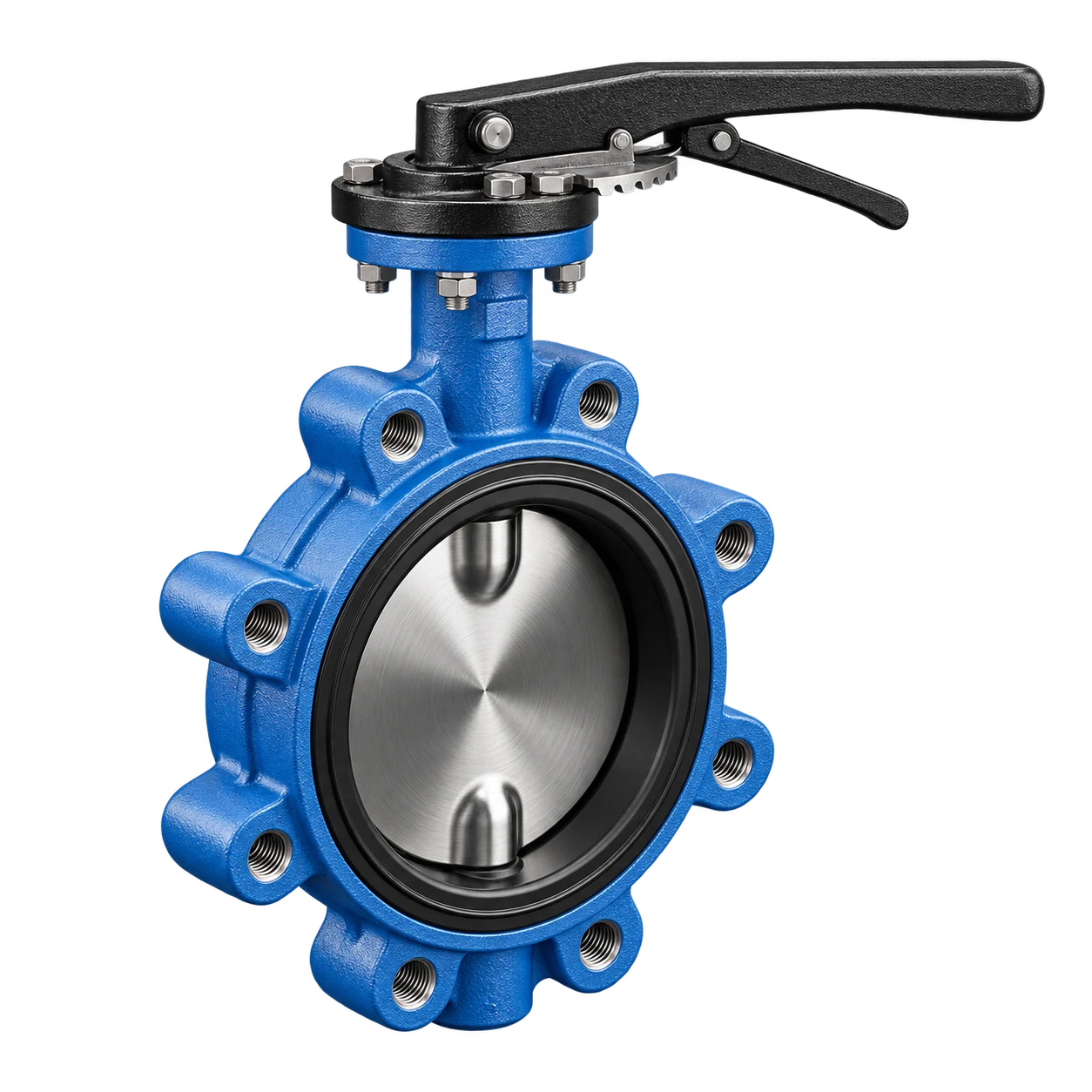
A Lug Butterfly Valve features integrated threaded bolt lugs encircling the entire valve body circumference. By threading mating flange studs directly into each lug tapped hole, the valve secures rigidly between twin piping flanges while occupying minimal face-to-face installation space. To compare body, sealing, and actuation options, explore our butterfly valve range.
At RUITO, every lug butterfly valve is evaluated as an integrated dynamic assembly—harmonizing body cast, disc alloy, seat elastomer, and blowout-proof stem. Configuration is validated against operating chemistry, operating pressure, temperature limits, and shut-off differential rather than arbitrary generic pressure ratings.
For critical downstream servicing and end-of-line isolation, designated configurations with verified bi-directional shut-off ratings provide secure pipeline dead-end sealing without requiring downstream counter-flange retention.
Bi-Directional Isolation
Ensures positive zero-leakage shut-off and precise throttling across full pressure gradients.
Threaded Lug Connection
Independent female thread lug drillings mate directly with standard ANSI / DIN flanges.
Versatile Actuation
ISO 5211 top flange readily accepts hand levers, worm gears, pneumatic, or electric units.
Application Customization
Precise seat elastomers and metallurgy tailored to pH, temperature, and abrasive media.
Need engineering guidance on valve selection and flange compatibility for your project?
Consult Our Valve SpecialistsEngineered Connection Security & Isolation Performance
Engineered for demanding piping networks requiring positive flange alignment, bi-directional bubble-tight shut-off, and versatile actuation interfaces, our lugged butterfly valves deliver uncompromising mechanical stability.
Independent Lug Threading
Precision tapped female lugs encircle the valve perimeter, providing dedicated bolt engagement directly into each hole to eliminate flange misalignments.
Verified Flange Interfacing
Engineered matching for DIN PN10/PN16 and ANSI Class 150 companion flanges ensures adequate thread depth, preventing clearance interferences and piping stress.
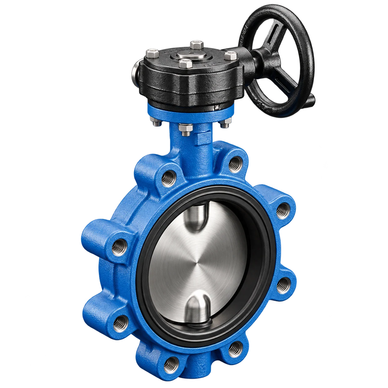
Flexible Actuation Platforms
Direct-mount ISO 5211 top flange readily connects manual hand levers, low-torque worm gearboxes, pneumatic cylinders, or electric rotary actuators.
Dedicated Dead-End Isolation
Qualified configurations allow secure downstream pipeline servicing and line terminal closure without requiring counter-flange retention up to 10 bar.
Need expert assistance determining flange rating and bolt length configurations?
Consult Our Valve SpecialistsEngineered Anatomical Structure for Robust Piping Integrity
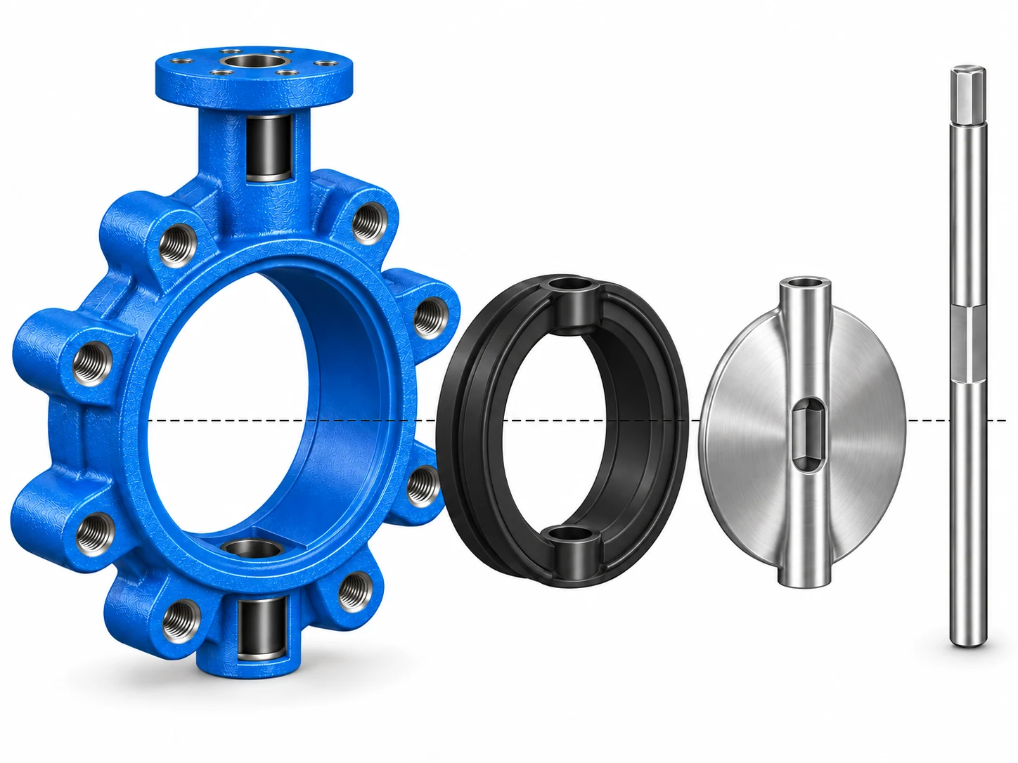
Building upon a high-flow concentric pathway, our lug butterfly valves feature integral threaded perimeter lugs that unify the body cast, disc profile, resilient elastomer seat, and drive shaft into an exceptionally rigid isolation unit.
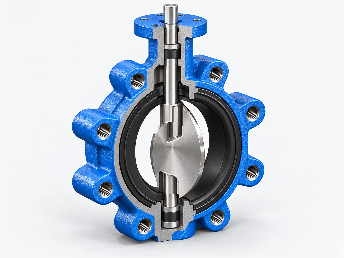
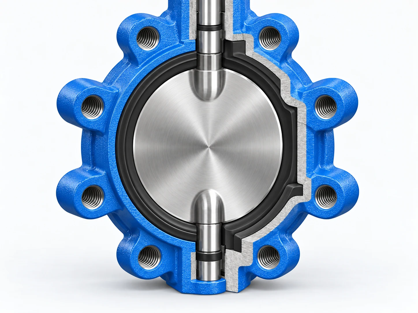
Engineering Sectional View & Precision Component Identification
Threaded Lug Ductile Iron Body
High-grade EN-GJS-450-10 casting with fusion-bonded epoxy coating. Features tapped metric/UNC lug bolting holes around the full circumference to absorb piping shear.
Hydrodynamic Valve Disc
Smoothly contoured disc available in CF8M (SS316) or nickel-plated ductile iron, engineered with thin profile edge geometries to maximize Kv flow coefficients and minimize pressure drops.
Resilient Elastomer Body Liner
Tongue-and-groove or vulcanized EPDM/NBR cartridge seat wrapping completely into flange faces, providing both bubble-tight bi-directional seat sealing and eliminating external flange gaskets.
Heavy-Duty One-Piece Stem Shaft
High-tensile stainless steel shaft with blowout-proof retention, upper/lower PTFE self-lubricating sleeve bushings, and dual O-ring packing to withstand high operating torques.
ISO 5211 Direct Actuator Mount
Standardized multi-drilled top mounting pad with standardized square drive stem end, enabling immediate bracket-free mounting of manual levers, gearboxes, or automated actuators.
Integrated Perimeter Lugs
Direct cast threaded bosses provide clear bolted positioning from either side of the pipeline without thru-bolts slipping.
Ultra-Compact Face-to-Face
Complies with ISO 5752 series 20 and EN 558 short dimensions, saving significant installation space and reducing pipeline dead weight.
Unified Actuation Compatibility
Direct-fit drive stem and ISO top flange form a backlash-free transmission geometry, facilitating on-site actuator interchangeability.
Looking for dimensional drawings (GA Drawings) or custom body drillings?
Download Technical GA & CAD DataEngineered Disc-to-Seat Geometry for Zero-Leakage Pipeline Sealing
Bi-directional tight shut-off relies on the engineered interference fit among the contoured disc edge, elastomeric seat compression, and dual stem journals rather than a single component rating.
Continuous Sealing Contact
Spherical disc machining establishes an uninterrupted 360-degree seal perimeter against the resilient seat, preventing bypass leakage even during pressure fluctuations.
Operating Differential Pressure Verification
Sealing capabilities are verified according to active working pressure and maximum shut-off differential (ΔP), guaranteeing reliable valve seating under actual fluid loads.
Systemic Media Matching
Formulations of elastomers and auxiliary O-rings are specifically paired with operational temperature and fluid chemistries to preserve resilience and prevent premature swelling.
Consistent Bi-Directional Isolation
Controlled angular positioning and precise seat compression curves deliver repeatable bubble-tight shut-off across repetitive cycling sequences.
Validated Differential Boundaries
Shut-off ratings correspond to verified nominal diameters and terminal pressure conditions, preventing unexpected seal blow-by under sudden line surges.
Holistic Assembly Cohesion
The valve body cast, contoured disc edge, resilient liner, and primary stem seals act as a synchronized assembly for lasting fluid containment.
Need engineering verification on seat elastomer grades and differential shut-off pressures?
Consult Sealing EngineersHarmonized Metallurgy and Elastomers for Harsh Process Fluids
Valve longevity is determined by aligning the full wetted assembly—ductile iron body, precision disc alloy, resilient seat liner, and high-tensile stem—with chemical medium, thermal boundaries, and solids content. When the duty requires a continuous fluoropolymer wetted barrier, compare our PTFE-lined butterfly valves against the actual fluid chemistry and pressure-temperature limits.
Unsure about fluid compatibility or metallurgy recommendations for your media?
Request Material BOM AssessmentEngineered Isolation for Diverse Industrial Fluid Systems
From municipal drinking water to hydrocarbon skids and clean utility gases, our lug butterfly valves deliver calibrated bubble-tight shut-off precisely matched to process fluid characteristics and operational pressures.
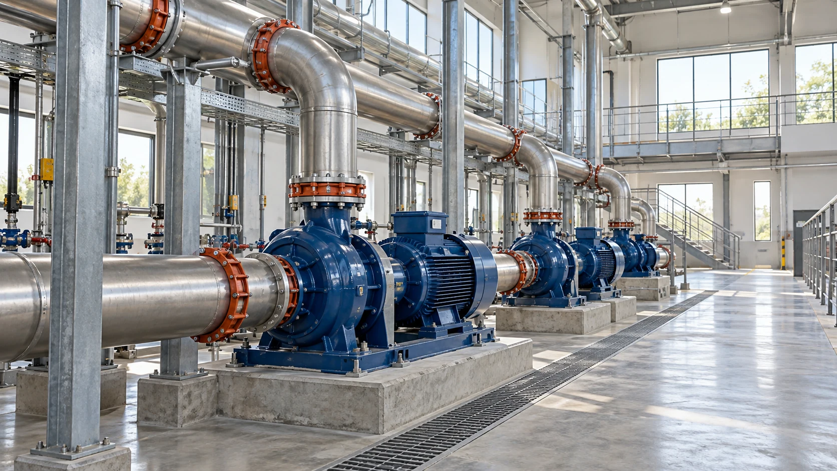 Municipal Water
Potable & Utility Water Pipelines
Engineered with ductile iron bodies and NSF/WRAS-grade EPDM liners, providing low-torque bi-directional isolation across municipal pumping stations and plant distribution mains.
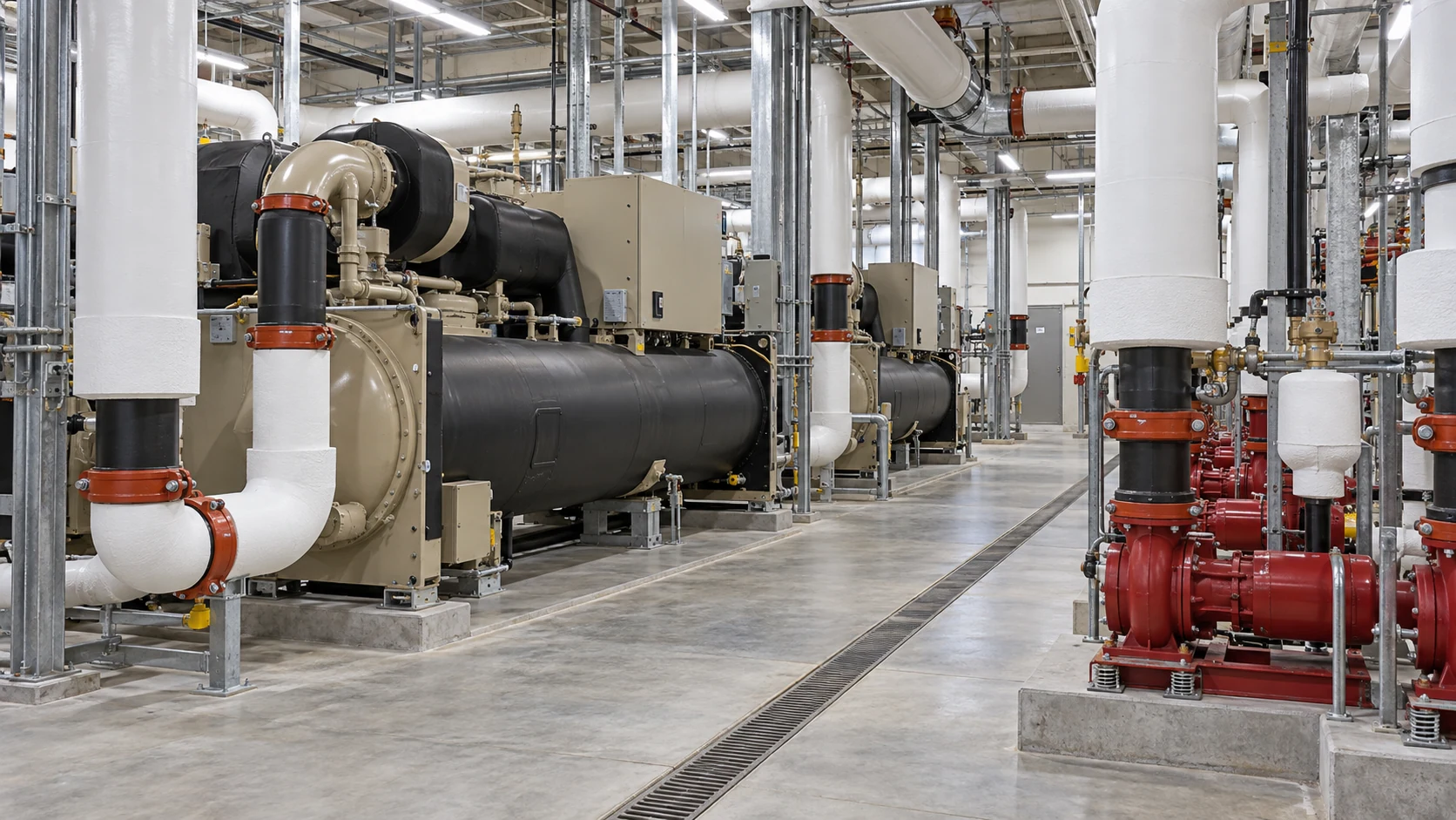 HVAC & Cooling
Chilled Water & Cooling Towers
Designed for continuous thermal cycling in commercial chillers and district heating loops, eliminating condensation leakage while supporting rapid actuator modulation.
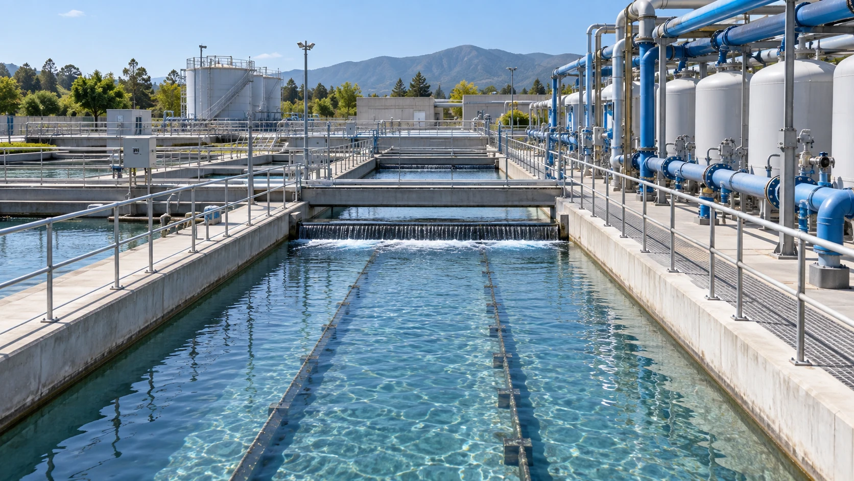 Water Reclamation
Secondary Effluent & Reuse Systems
Equipped with streamlined CF8M stainless steel discs and vulcanized liners to prevent particle accumulation and cavitation in clarified tertiary treatment circuits.
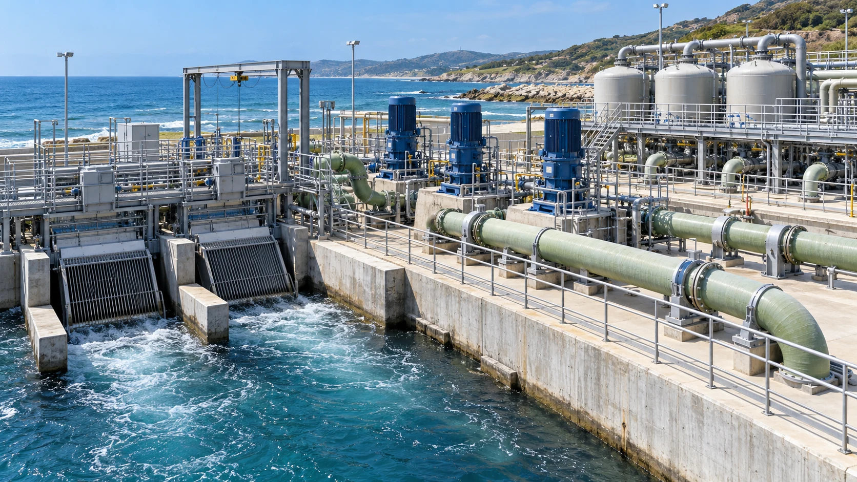 Marine & Desalination
Seawater Intake & Pretreatment
Configured with C95800 nickel aluminum bronze trim or Monel shafts to resist pitting, micro-crevice attack, and galvanic degradation in marine intake pipelines.
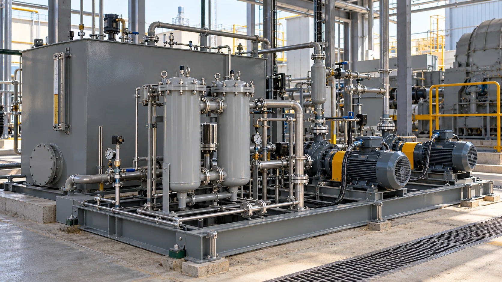 Lubrication & Fuel
Industrial Lubrication Skids
Utilizes oil-resistant NBR elastomeric cartridges rated up to 70°C, ensuring swelling-free operation and verified stem gland retention across machine lube lines.
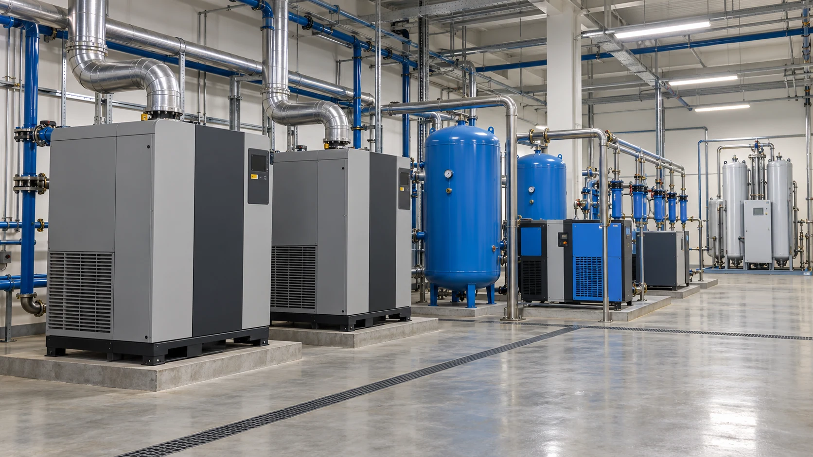 Clean Utility Gases
Compressed Air & N2 Networks
Specifically assembled and helium leak-tested to achieve ISO 5208 Rate A closure under pneumatic pressures up to 6 bar, preventing pressure depletion in plant headers.
Have a non-standard fluid or specific pipeline chemistry requirement?
Consult Application EngineersOperating Envelopes Must Be Concurrently Validated
Pressure ratings are strictly temperature-dependent. Maximum allowable pipeline pressure and peak thermal limits cannot be selected independently from different configurations.
Typical Operating Windows (P-T Envelope)
Nominal PN10/PN16 baseline up to 20°C; thermal derating applied above 40°C in continuous glycol service.
Restricted to non-abrasive, screened secondary effluent to maintain resilient seat compression life.
Controlled pressure and low temperature boundary preventing cavitation under chlorinated cooling water.
Optimized for hydrocarbon lubrication skids with verified elastomer anti-swelling characteristics.
Calibrated soft seat sealing limit for pneumatic gas tight-isolation (Rate A, zero bubbles).
Baseline Specification
Covers standard industrial metric sizes (2" to 12"). Actual permissible working pressures must be confirmed alongside media temperature curves.
Water Fluid Envelope
PN10 configurations hold 10 barg max; PN16 configurations permit up to 16 barg under room temperature water. Dynamic water hammer transient allowances apply.
Industrial Media Bounds
Strict limits apply per BOM: Mineral oil ≤10 barg (70°C max), Seawater ≤10 barg (40°C max), Clean Air/N2 capped at 6 barg for verified gas tightness.
Dead-End Isolation Spec
Qualified on DN50–200 water configurations (5–40°C). Permitted for downstream line dismantling without counter-flange retention only under verified ratings.
Need verified P-T curves or differential pressure calculations for your line?
Request P-T Engineering DataField-Proven Actuation for Manual & Automated Flow Control
Lug butterfly valves readily adapt to manual levers, heavy-duty gearboxes, electric multi-turn drives, or pneumatic quarter-turn actuators, calibrated specifically to pipe diameter, shut-off differential, and automation needs.
Provides direct 90-degree manual position indication and rapid emergency throttling. Optimized for low-to-moderate operating torques across accessible plant pipeline runs.
Equipped with heavy-duty mechanical gear ratio reduction to overcome substantial line differential pressures smoothly while preventing backdrive from fluid hydrodynamic forces.
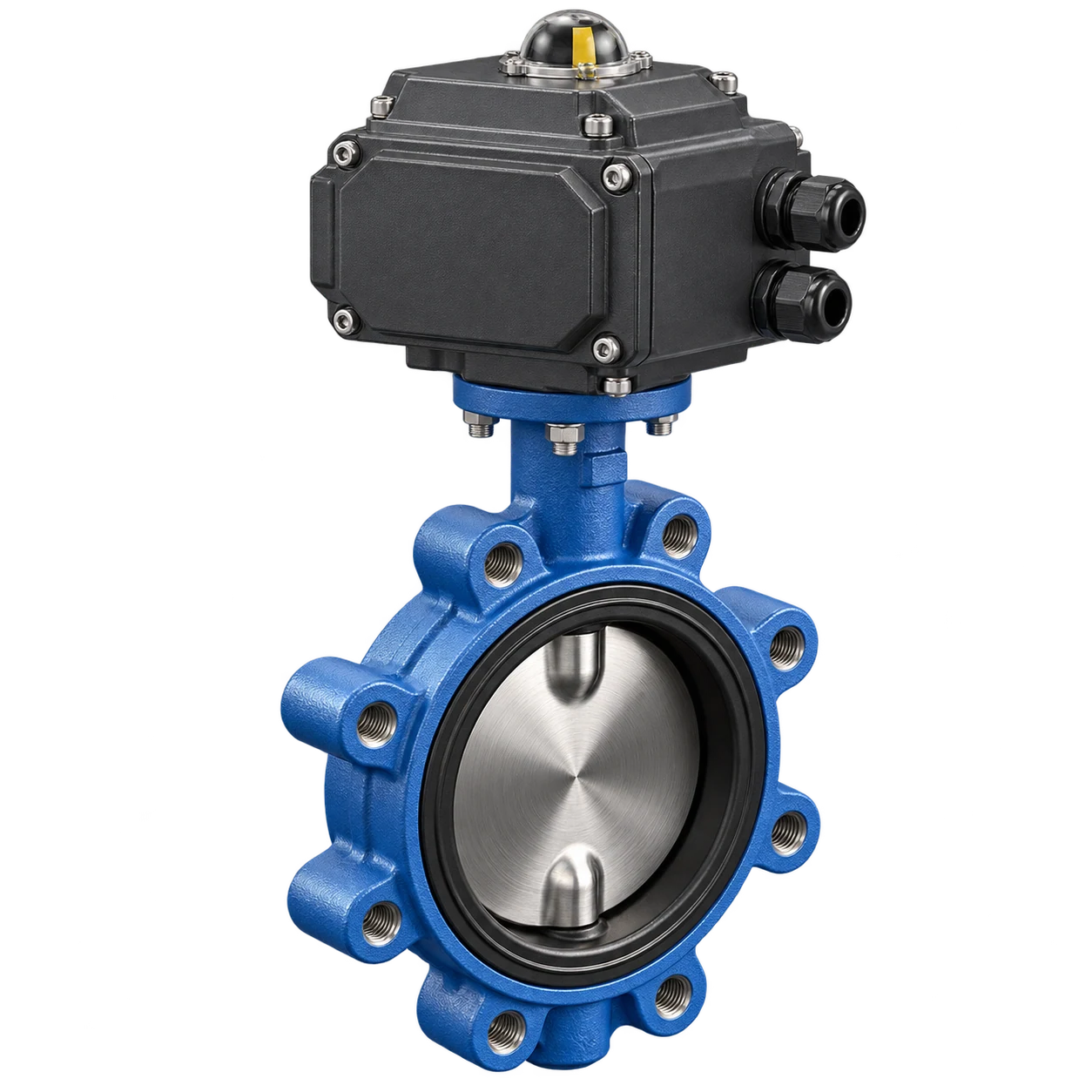
Integrated motor drive with electronic torque limiters and 4–20mA / Modbus feedback, enabling automated loop throttling and remote plant room isolation without compressed air supply.
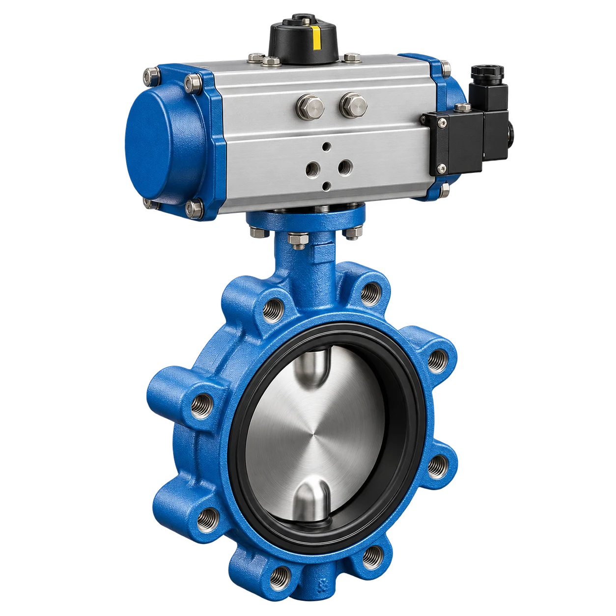
Delivers rapid 1–3 second stroke speeds and spring-return fail-safe security (fail-close or fail-open). Engineered for continuous cycling in process automation and water treatment skids.
Actuator Sizing Must Account for Dynamic Process Torque
Actuation packages cannot be selected by valve nominal size (DN) alone. Operating torque varies considerably with fluid medium, elastomer hardness, operating temperature, and differential pressure across the disc.
Peak shut-off pressure across the closed disc directly dictates breakout torque and elastomer compression resistance.
Calculated with safety factors (≥25-30%) including breakaway, run-torque, and seating torque under wet or dry media.
Occasional maintenance shut-off requires only manual levers, while continuous industrial pacing necessitates pneumatic units.
Specifying limit switch boxes, NAMUR solenoid valves, positioners, or 4-20mA smart transmitters ensures system cohesion.
Understanding Pipeline Connection & Dead-End Capabilities
While both valve profiles share identical disc and elastomer sealing geometries, body bolt hole threading, flange installation load, and end-of-line servicing safety dictate structural selection.
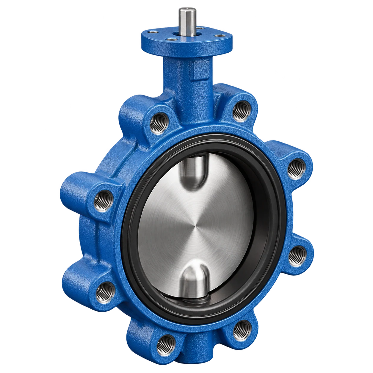
Lug Butterfly Valve
Threaded bolt lugs encircle the entire outer body circumference. Studs engage directly into the valve casting from either side, enabling positive centering and independent downstream pipe servicing.
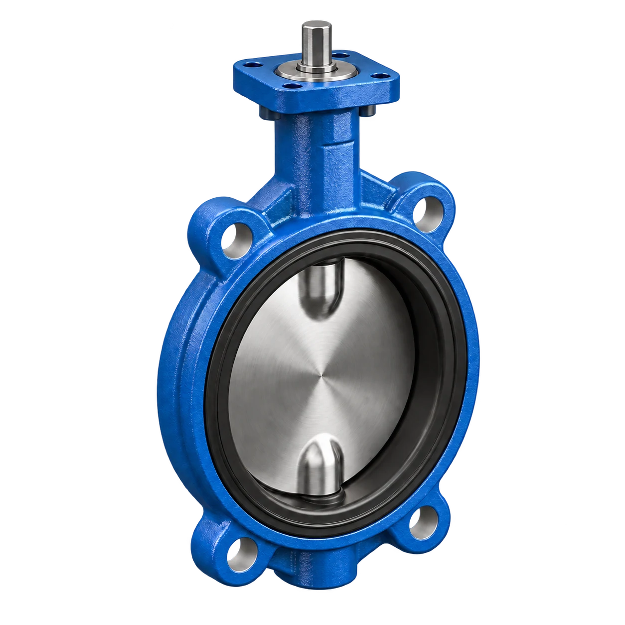
Wafer Butterfly Valve
Compact body profile sandwiched between two companion flanges using continuous through-bolts. Highly cost-effective and lightweight, requiring both flanges to remain clamped to maintain seal compression. If a through-bolted inter-flange body is specified, review our wafer butterfly valves for that connection option.
Capped at DN300 to ensure uniform threaded lug load distribution without structural casting distortion.
Broad size availability up to large diameter water intake lines with economical material consumption.
Precision Flange Alignment, Disc Clearance & Dead-End Safety
Field reliability depends directly on verified companion flange internal diameter, adequate lug bolt thread engagement, unimpeded disc opening envelope, and strict adherence to validated dead-end pressure boundaries.
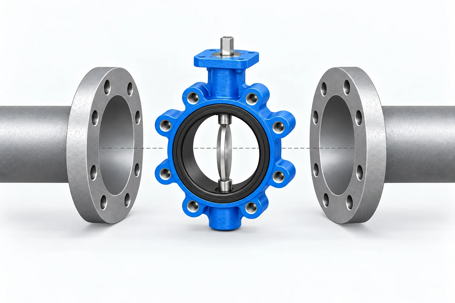
Companion Flange Matching
DIN / ANSI / JISAudit companion pipe flanges against valve drilling pattern (PN10/16 or Class 150). Ensure flange face raised surface and interior pipe schedule match specified flange inner diameter to prevent gasket seal distortion.
Disc Clearance & Arc Envelope
Mechanical ClearanceInspect upstream and downstream pipe wall and flange bore dimensions prior to torquing. Verify that the contoured disc edge swings freely into the adjacent pipe without contact interference during full 90° stroke.
Lug Tapped Hole & Stud Engagement
Thread VerificationConfirm metric or UNC thread pitch, nominal bolt length, and minimum thread engagement depth into each perimeter lug. Torque flange studs evenly in a diagonal star sequence to prevent casting stress concentration.
Dead-End Isolation Boundary Check
≤10 bar Terminal RatingFor single-sided downstream line dismantling, confirm the installed unit is certified for dead-end terminal isolation (RUITO water baseline DN50–200, 5–40°C, shut-off ΔP ≤10 bar) before unbolting downstream piping.
Periodic Operational Cycling
Regularly stroke manual levers, gearboxes, or actuators through full travel to prevent elastomer seat crystallization and ensure limit switches deliver true open/close status.
Process Variable Re-Verification
If system working pressure, operating temperature excursions, or chemical inhibitor concentrations shift, re-verify seat elastomer and stem packing resistance ratings with engineering.
OEM Controlled Spare Parts
Replace worn resilient liners, O-rings, and stem bushings exclusively with serialized RUITO replacement cartridges matching original BOM formulation to ensure zero-leakage closure.
Rigorous Hydrostatic, Seat Closure & Dimensional Verification
Every RUITO lug butterfly valve undergoes strict serialized testing compliant with EN 12266-1 Rate A and ISO 5208 standards, confirming structural shell integrity, 100% zero-leakage shut-off, and precise flange fit before factory dispatch. Review RUITO's manufacturing and quality processes as part of supplier qualification.
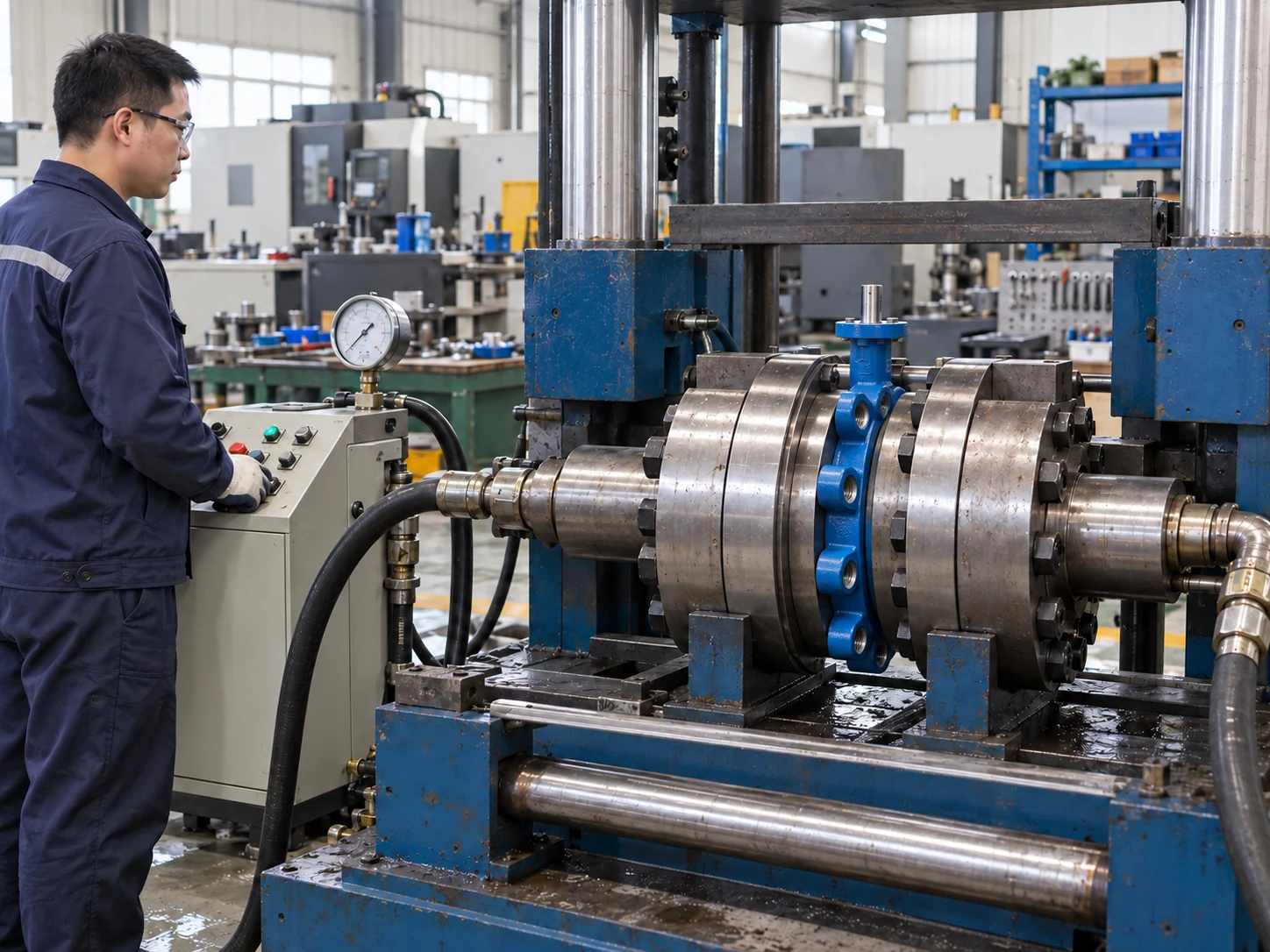
Raw Material & Casting Audit
Incoming InspectionSpectrometric metallurgy verification on ductile iron castings, CF8M discs, and Monel shafts. Elastomer durometer testing and epoxy coating thickness gauging ensure compliance prior to machining.
Critical Dimensions & Threading
Machining & AssemblyPrecision CMM inspection of tapped perimeter lug hole spacing, face-to-face dimensions (ISO 5752 series 20), disc edge sphericity, and ISO 5211 direct-mounting actuator pad concentricity.
Hydrostatic Shell & Seat Closure
Pressure Testing1.5× PN hydrostatic shell test confirms casting pressure boundary. 1.1× PN soft-seat bi-directional closure test validates bubble-tight zero-leakage containment under sustained differential load.
Functional Torque & Final Release
Final InspectionFull-travel dynamic torque profiling, manual lock-plate indexing, actuator travel limit alignment, clean-pack labeling, and serialization marking tied directly to inspection documentation.
Complete Technical Package & Verified Serialized Traceability
Every RUITO lug butterfly valve delivers comprehensive engineering documentation aligned with physical BOM configuration, tying design drawings, material heat batches, hydrostatic test curves, and QA dossiers to individual product serial numbers.
Technical Data & General Arrangement
Verified dimensional envelopes, lug bolt hole circles, actuator top flange geometry (ISO 5211), and companion pipe clearance for piping layout reviews.
Bill of Materials Specification
Itemized wetted metallurgy audit (EN-GJS-450-10, CF8M, C95800), elastomer compound formulation (EPDM, NBR), stem grade, and epoxy coating baseline.
P–T Envelopes & Dynamic Torque
Empirical flow coefficients (Kv / Cv) across opening angles, pressure drop charts, and breakaway/run seating torques calibrated to shut-off ΔP.
ITP Quality Plan & IOM Manual
Standard or client-customized Inspection & Test Plan (ITP) paired with field Installation, Operation, and Preventive Maintenance guidelines.
Manufacturing Data Record (MDR Package)
Consolidated binder matching EN 10204 Type 3.1 Mill Test Reports (chemical analysis & mechanical yield), serialized pressure test charts, durometer certs, coating dry film thickness (DFT) logs, and final inspection release sign-offs tied to shipment PO.
Stainless steel engraved tag stamped with unique valve serial code, size, pressure class, and factory batch.
Manufacturing order freezes specific metallurgy, disc geometry, and elastomer compound against revision-controlled design drawings.
Direct link from casting heat numbers to certified spectrometric analysis and elastomer compound curing batches.
Digitized calibration records of test benches, testing engineer badge ID, and shell/seat pressure holding duration charts.
Serialized crate manifests and container barcodes synchronizing physical deliveries with pre-dispatched digital QA dossiers.
Require specialized MDR documentation or project-specific ITP approval?
Request Project Documentation PackageEngineering Parameters Required for Accurate Lug Valve Specification
Precise valve sizing extends far beyond generic DN and PN classifications. Provide these essential parameters to ensure complete harmonization between your piping chemistry, operating pressure envelopes, actuator duty cycles, and sealing boundaries.
Process Medium
Fluid Chemistry & StateClean water, glycol loops, industrial mineral oils, and clean gases require strictly segregated elastomer and disc BOM formulations.
Size & Rating
DN / NPS & Pressure ClassStandard baseline spans DN50–300. Body lug threading must correspond strictly to mating companion flange drilling patterns.
Temp & Pressure
Concurrent P–T LimitsMaximum pressure and temperature cannot be selected independently from different configurations. Both must stand concurrently.
Shut-Off ΔP
Maximum Differential BarrierDirectly governs dynamic seating torque, elastomer compression thickness, and determines appropriate gear or actuator output sizing.
Flange Standard
Drilling & Bore DimensionsEnsures correct metric vs UNC lug thread tapping and validates disc opening envelope clearance against companion pipe walls.
Actuation Mode
Manual, Electric, or PneumaticSpecify operating cycle frequency and fail-safe automation protocols (spring return fail-close, 4–20mA Modbus loop integration).
Dead-End Isolation
Downstream Line ServicingRequires dedicated dead-end certified construction. RUITO water protocol limits terminal dead-end service to DN50–200, ≤10 bar, 5–40°C.
Quality Dossier
Testing & Third-Party AuditProject testing criteria and customer inspection hold points are frozen into production travelers before machining commences.
From Operating Parameters to Validated Valve Configuration
Our structured 4-step engineering verification ensures zero misapplication risks on critical industrial projects.
Condition Intake
Engineering evaluation of medium chemistry, operating P–T windows, shut-off ΔP, and companion pipe schedule.
Technical Audit
Verification of elastomer seat swelling index, disc opening envelope clearance, and required actuator sizing torques.
Configuration Freeze
Freezing accurate bill of materials (BOM), verified dead-end rating boundaries, and actuation interface standards.
Drawing & QA Approval
Submittal of project GA drawings, certified flow curves, and agreed ITP inspection hold points prior to machining release.
Have your piping parameters ready, or need engineering assistance preparing your RFQ?
Submit Project RFQ & Engineering Parameters
Looking for the Right Lug Butterfly Valve for Your Pipeline?
Share your essential procurement or project criteria with us. RUITO's technical engineering group verifies exact chemical compatibility, operating P-T envelopes, and mating flange standards to deliver verified valve configurations and competitive commercial terms.
-
Engineered Configuration SupportComprehensive matching of wetted metallurgy, elastomer swelling limits, shut-off ΔP, and actuation torque.
-
Explicit Operating BoundariesDefined engineering ratings tied strictly to verified temperature and pressure curves, preventing misapplication.
-
Project Documentation PackagesFull provision of certified Datasheets, 2D/3D GA models, BOM freeze records, ITP test plans, and MDR dossiers.
-
Controlled Manufacturing & Serialized QCEvery valve undergoes EN 12266-1 Rate A hydrostatic pressure and zero-leakage seat closure testing prior to shipment.
-
Dedicated OEM & Project ProcurementFlexible volume manufacturing for regional valve distributors, skid package builders, and turnkey EPC engineering contractors.
Request Lug Valve Quotation
Complete basic details below. Our engineering group will assist in freezing your technical configuration.