
Plan butterfly valve gearbox maintenance from the selected operator manual, actual duty and recorded condition. Identify the installed assembly before inspecting, lubricating or adjusting it. Generic schedules cannot establish the correct lubricant, service interval or repair procedure for every gearbox.
A handwheel becomes harder to turn and the maintenance request immediately calls for more grease. Yet the cause could involve changed valve differential, a damaged connection, corrosion or the operator itself. Record the symptom and operating conditions before choosing a maintenance action, then use the selected valve and operator information to define the work.
1. What starts butterfly valve gearbox maintenance?
Start butterfly valve gearbox maintenance by identifying the valve, operator, installed drive parts and applicable manual revisions. Link the maintenance request to the asset tag and observed symptom. A known assembly baseline lets your team choose the correct inspection scope, lubricant information, spare-parts references and acceptance requirements before physical work begins.
What should the work request contain?
Record what changed. Include the location, symptom, when it appeared, recent operating conditions and any earlier adjustment or replacement. Keep the valve duty with the operator record because a changed closing differential can alter handwheel effort without proving an internal gearbox fault. Photographs support condition reporting, while the selected documents determine what work is permitted and what supporting information remains missing.
- Identify the valve, operator and installed configuration.
- Record the symptom and recent operating conditions.
- Locate the selected manuals and previous work history.
Key takeaway: Begin maintenance with an identified asset and a clear condition report.
| Check | What you should confirm |
|---|---|
| Identity | Asset and operator records describe one assembly |
| Symptom | Observed change has a location and time context |
| Documents | Applicable maintenance and parts references are available |
2. What isolation precedes butterfly valve gearbox maintenance?
Physical butterfly valve gearbox maintenance needs the isolation, stored-energy control and support arrangements required for the actual installation and selected work scope. A stationary handwheel does not establish that the valve is unloaded or safe to dismantle. Removing an operator can also affect the means of retaining the valve position.
What should the maintenance planner confirm?
Define the work boundary. State whether the task is an external observation, an authorized movement check, operator removal or internal service, then apply the corresponding site and manufacturer requirements. Retain the actual process conditions and any attached powered equipment in that assessment. This article supplies a planning framework; the selected valve and operator instructions govern physical dismantling, support and adjustment steps.
- Define the exact physical work scope before starting.
- Apply the required isolation and stored-energy controls.
- Plan support and position retention for operator removal.
Key takeaway: Make the required isolation and support arrangements part of the defined maintenance scope.
| Check | What you should confirm |
|---|---|
| Scope | External observation and dismantling remain distinct |
| Energy | Actual process and attached drives are addressed |
| Support | Removal does not leave uncontrolled loads or movement |
3. What condition guides butterfly valve gearbox maintenance?
External butterfly valve gearbox maintenance should document housing condition, joints, mounting features, handwheel, fasteners and visible contamination at their actual locations. Look for changes from the accepted baseline, including corrosion, impact damage or movement at the support. A photograph records an observation without proving its cause or hidden internal condition.
How should your team describe a suspected leak?
Be precise about the surface. Record which joint is wet, what material appears present and whether the source could be nearby pipework, washdown or another component. Distinguish a condition observation from an established seal failure, then request the selected inspection scope where the cause remains uncertain. Housing cracks or distorted mounting faces require a repair or replacement review before routine lubrication becomes the assumed remedy.
- Photograph damage and contamination with clear locations.
- Compare mounting condition with the accepted baseline.
- Separate observed wetness from an established failure cause.
Key takeaway: Use a factual external condition record to guide the next authorized inspection.
| Check | What you should confirm |
|---|---|
| Housing | Cracks, corrosion and impact damage are located |
| Joints | Wet areas and possible sources are recorded |
| Mounting | Movement or distortion receives separate review |
4. What lubrication fits butterfly valve gearbox maintenance?
Lubrication during butterfly valve gearbox maintenance must follow the selected operator requirements for lubricant type, quantity, method and interval. Some assemblies are supplied with a defined sealed lubrication arrangement, while others have specified servicing provisions. A visible housing or familiar grease colour cannot establish which policy applies to the installed unit.
What should be checked before adding lubricant?
Read the selected instruction. Confirm the lubricant designation, compatibility requirements, service conditions and authorized access point or procedure before arranging work. Record what was used and why, including any instruction that calls for replacement or approved internal service instead of routine replenishment. Mixing products or opening a sealed operator on a generic schedule can create a different problem while leaving the original symptom unexplained.
- Confirm the selected lubrication policy and designation.
- Use only the specified method and approved service scope.
- Record the product, quantity where required and work basis.
Key takeaway: Treat lubrication as a selected-product requirement linked to the recorded condition and duty.
| Check | What you should confirm |
|---|---|
| Policy | Selected manual defines whether servicing is required |
| Lubricant | Type and compatibility are explicitly identified |
| Record | Actual maintenance action remains traceable |
5. What movement informs butterfly valve gearbox maintenance?
Authorized movement checks within butterfly valve gearbox maintenance should compare handwheel input, transmitted shaft motion and accepted valve endpoints. Record the operating conditions under which observations are made. A change in effort, unusual lost motion or inconsistent indication needs investigation across the assembly rather than immediate attribution to a single internal component.
What should a movement record distinguish?
Observe each stage separately. State whether the handwheel turns, whether the valve shaft responds and how the pointer relates to the accepted endpoint references. Use the selected procedure and permitted conditions for any test, retaining the observations without inventing a diagnosis. A damaged coupling, changed process load and operator fault can produce different symptoms that need different evidence and work scopes.
- Record input movement and actual shaft response separately.
- Retain operating conditions with the observation.
- Compare indication with accepted endpoint references.
Key takeaway: Use movement observations to locate unanswered questions along the complete drive path.
| Check | What you should confirm |
|---|---|
| Input | Handwheel motion and effort have a stated context |
| Transmission | Actual shaft response is observed where permitted |
| Indication | Pointer and endpoint references are compared separately |
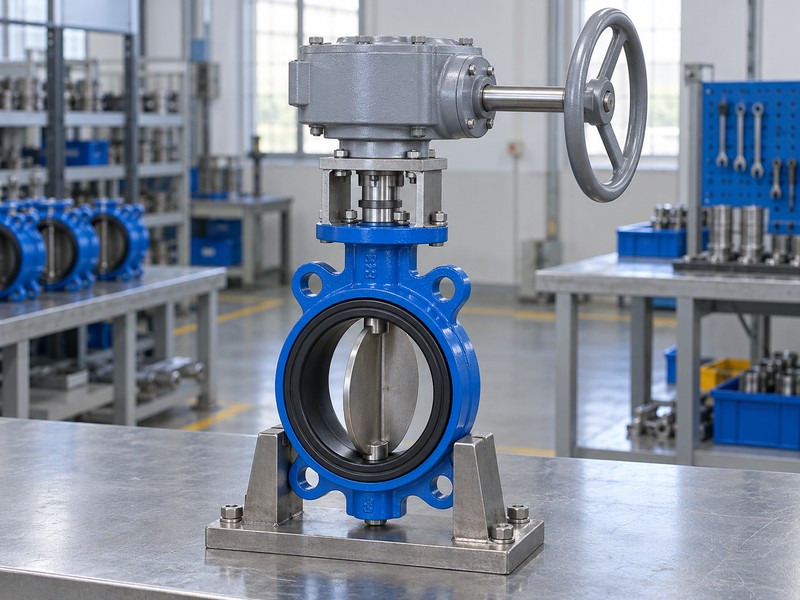
6. What turns inform butterfly valve gearbox maintenance?
Turn information used in butterfly valve gearbox maintenance should refer to the complete operator and its accepted output travel. A changed count may reflect the test method, endpoint definition, extra reduction or a mechanical condition that needs investigation. An isolated turn number without those references cannot establish wear or correct travel.
How can the motion chart support a baseline?
Use it to separate quantities. The chart illustrates an ideal fixed ratio, with input turns horizontally and output shaft angle vertically; it contains no measured maintenance trend. Actual baseline counts must come from the selected assembly and accepted checking method. Compare like conditions and endpoints, then investigate a difference through the selected procedure instead of declaring a failure threshold from a conceptual graph.
- Identify the complete operator and accepted travel references.
- Record the method and conditions used for turn observations.
- Keep conceptual motion relationships separate from measured trends.
Key takeaway: Compare actual turn observations against a defined baseline using the selected checking method.
| Check | What you should confirm |
|---|---|
| Baseline | Actual assembly data define the comparison |
| Method | Consistent endpoints and conditions support comparison |
| Chart | Ideal kinematics supply no wear limit or measured result |

7. What connections affect butterfly valve gearbox maintenance?
Connections reviewed during butterfly valve gearbox maintenance include the mounting attachment, output drive, coupling, locating features and specified fasteners. Their condition can affect motion transmission and alignment. A joint that appears tight still needs the selected dimensional and assembly basis when the work involves removal, replacement or a changed mounting arrangement.
What should follow an operator or coupling replacement?
Recheck the affected interfaces. ISO 5211 addresses part-turn attachments; selected mating details remain necessary for the actual assembly. Confirm drive profile, engagement, retention, thread specification and correct face seating using the approved documents. Record any revised bush, bracket or fastener so future maintenance does not assume that the original configuration still describes the installed package.
- Identify mounting and drive connections independently.
- Recheck fit and retention after affected replacements.
- Record changed brackets, bushes and specified fasteners.
Key takeaway: Repeat the interface checks affected by a maintenance replacement or configuration change.
| Check | What you should confirm |
|---|---|
| Attachment | Mounting details match the accepted configuration |
| Drive | Profile, engagement and retention receive review |
| Change | Installed substitutions remain documented |
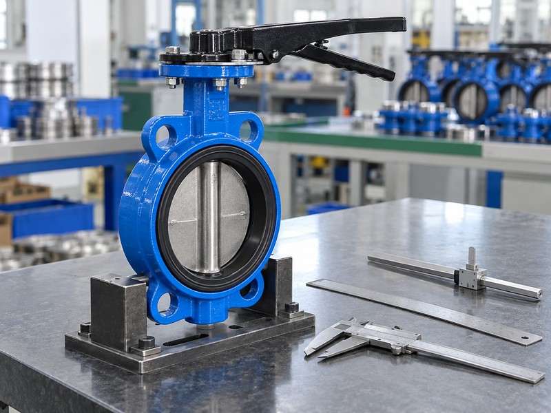
8. What exposure changes butterfly valve gearbox maintenance?
External exposure can change the priorities within butterfly valve gearbox maintenance, especially where moisture, corrosion, dirt or restricted access affects the operator. Record the actual environment and any change since commissioning. A protection designation has defined conditions and cannot replace inspection evidence or justify operating indefinitely after water ingress or physical damage.
What should follow a changed installation condition?
Review the difference explicitly. A new washdown practice, altered insulation, standing water or relocated handwheel may change exposure and service access even when the valve duty stays the same. Compare that condition with the selected operator limits and maintenance information. Keep process-medium compatibility separate from external corrosion questions; the same gearbox exterior can sit above different valve wetted-material configurations.
- Record actual moisture, dirt and corrosion exposure.
- Review changes in access and installation conditions.
- Compare exposure with selected operator limits and records.
Key takeaway: Update maintenance planning when the installation environment or access arrangement changes.
| Check | What you should confirm |
|---|---|
| Exposure | Actual conditions and recent changes are described |
| Protection | Selected limits accompany their test conditions |
| Access | Inspection and service remain physically possible |
9. What schedule suits butterfly valve gearbox maintenance?
A schedule for butterfly valve gearbox maintenance should combine selected manufacturer requirements with actual duty, exposure, condition history and site planning. Avoid assigning every operator one universal interval. Frequent movement, long idle periods or changed operating conditions can raise different questions that the equipment-specific information and maintenance history must address.
How should the planner use the previous records?
Review the history as evidence. Track observed condition, authorized work, parts replaced and the conditions associated with repeated symptoms, then identify what the next planned task should resolve. Obtain current spare availability and service scope for the actual operator rather than assuming every internal item remains individually replaceable. Keep the reason for any adjusted schedule with the asset record so the plan can be reviewed later.
- Use selected requirements with actual duty and exposure.
- Retain observed condition and repeated-symptom history.
- Record the basis for planned tasks and changed intervals.
Key takeaway: Set maintenance tasks and timing from selected requirements and the actual asset history.
| Check | What you should confirm |
|---|---|
| Requirements | Selected manual supplies applicable service provisions |
| History | Condition and previous work inform the plan |
| Planning | Next task has a documented purpose and scope |
10. What closes butterfly valve gearbox maintenance?
Close butterfly valve gearbox maintenance after the defined work and its affected verification requirements have been completed and recorded. Match the installed operator, drive parts and settings with the accepted configuration. Inspection, authorized movement and any separate valve sealing requirement need their applicable evidence before the asset receives its site return-to-service decision.
What belongs in the completed work record?
Leave a usable handover. Record the initial symptom, observed condition, actual work, installed parts, revised documents and acceptance results required by the selected procedure. Note unresolved issues and restrictions instead of hiding them in a general completed status. RUITO can review supplied valve-assembly records and support an enquiry, while site authorization and the selected maintenance instructions govern the physical return-to-service process.
- Record actual work, installed parts and revised references.
- Retain the required affected verification results.
- State unresolved issues and applicable restrictions clearly.
Key takeaway: Close the maintenance record with the actual work and evidence needed for the asset handover.
| Check | What you should confirm |
|---|---|
| Work | Completed scope and installed parts are identified |
| Verification | Affected functions have the required evidence |
| Handover | Open issues and accepted status remain visible |
Send RUITO the valve and operator identification, operating conditions, maintenance history and clear condition photographs. We can review the supplied assembly information and identify the documents needed for a support or replacement enquiry. Contact us with the observed symptom and selected manual reference.
FAQ
Q1: Can I add grease whenever the handwheel becomes stiff?
Use the selected procedure. Changed valve loading, drive damage or another condition may need investigation before lubrication is appropriate.
Q2: What’s the best maintenance interval?
Use equipment-specific requirements. Combine the selected manual with actual duty, exposure and recorded condition rather than one universal schedule.
Q3: Can I remove the operator while the valve stays installed?
Only under the authorized selected-equipment procedure. Isolation, support and valve-position retention depend on the actual installation and work scope.
Q4: How do I know whether a changed turn count means wear?
Compare a defined baseline. Retain the same assembly, endpoints, test method and permitted operating conditions before investigating the difference.
Q5: Can the pointer prove the valve is ready for service?
No. Indication, accepted movement and any required leakage result need their applicable verification and site authorization.