
Fix retrofit mistakes by matching the switch, operating target and permitted mounting arrangement to an identified valve and operator. Select a tamper switch for butterfly valve applications within the documented assembly and approval scope. A device that fits physically can still monitor the wrong movement or fall outside the permitted replacement arrangement.
A replacement switch can match an old thread and contact count yet fail to follow the valve’s operating target. The panel may then receive a position signal that no longer matches intended valve movement. Check whether a documented replacement kit exists before treating that mismatch as a field-adjustment problem.
1. What identifies a tamper switch for butterfly valve application?
For a tamper switch for butterfly valve application, start with the actual valve and operator identity. Record manufacturer, model, size, existing switch arrangement and intended normal position. Similar handwheels or enclosures cannot establish that two assemblies share the same sensing mechanism or permitted accessories.
What must be known before a replacement is selected?
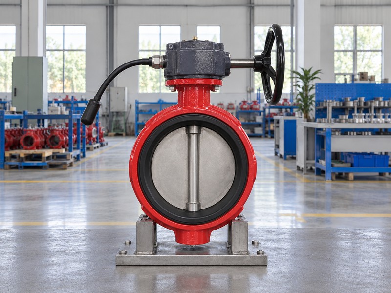
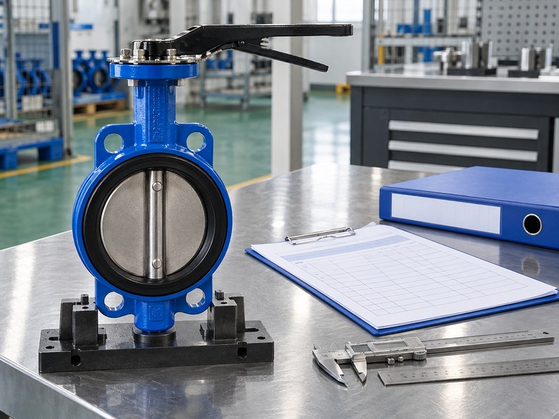
Read the existing markings and documents. Establish whether the job concerns an external switch, an integral operator component or a complete supervised assembly, then identify the corresponding manufacturer instructions. Record missing or unreadable information as an unresolved compatibility issue. The closed-disc exterior illustration shows no internal target, switch arrangement or RUITO product identity, so use actual photographs and records for the application review.
- Identify the valve and operator as separate components.
- Record existing switch identity and normal service position.
- Define the component or assembly proposed for replacement.
Key takeaway: An identified valve-and-operator arrangement provides the basis for reviewing a replacement switch.
| Check | What you should confirm |
|---|---|
| Valve | Model and actual service location are identified |
| Operator | Version and existing supervision arrangement are known |
| Replacement | Work boundary identifies the affected component |
2. Which tamper switch for butterfly valve type fits?
A tamper switch for butterfly valve application needs a device intended for its actual operating mechanism. Supervisory switches for butterfly operators, post indicators and outside-screw-and-yoke gate valves can use different mechanical targets. A shared supervisory purpose does not make their sensing and mounting arrangements interchangeable.
How do the monitored valve mechanisms differ?
Compare the operating target before the enclosure. The Potter OSYSU document describes a device whose trip rod engages a groove in an OS&Y valve stem. A butterfly arrangement can instead follow a feature of its operator, while a post-indicator arrangement follows its identified target assembly. A switch family serving several valve types still needs the correct installation arrangement for each application.
- Identify butterfly, post-indicator or OS&Y operating construction.
- Match the device with its documented mechanical target.
- Keep application-specific mounting instructions with the selected device.
Key takeaway: Choose the device family from the monitored mechanism, then check its exact application arrangement.
| Check | What you should confirm |
|---|---|
| Butterfly | Identified operator feature provides the sensing target |
| Post indicator | Selected indicator target operates its specified switch |
| OS&Y | Selected device follows its documented stem arrangement |
3. What target suits a tamper switch for butterfly valve retrofit?
In a tamper switch for butterfly valve retrofit, the target must move in the direction and range required by the selected sensing arrangement. Engagement at one visible position cannot demonstrate correct behavior through permitted valve movement. The operating feature and switch actuator need a documented relationship.
What does a trip-rod arrangement require?
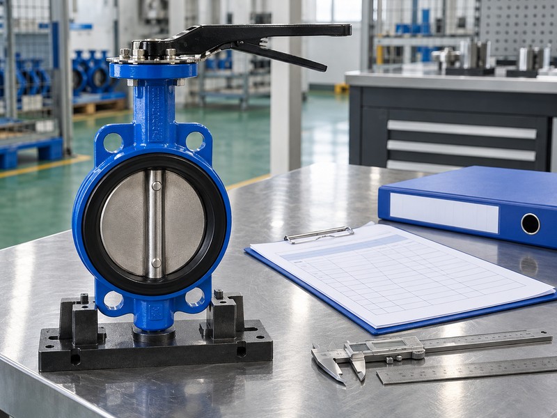
Use a product-specific example within its scope. The Potter PCVS instructions describe a spring-loaded trip rod operated by an identified butterfly-valve mechanism, with separate arrangements for post indicators. That example does not establish compatibility with every gearbox containing a plug or moving part. Review target location, movement direction, actuator engagement and permitted travel against the exact instructions without inventing a new operating feature.
- Identify the feature that actually operates the switch.
- Compare target motion with required actuator movement.
- Use documented engagement and permitted travel criteria.
Key takeaway: A documented target-to-actuator relationship supports selection; a convenient moving part does not.
| Check | What you should confirm |
|---|---|
| Target | Identified operator feature drives the sensing arrangement |
| Motion | Direction agrees with selected switch operation |
| Travel | Engagement remains within documented operating limits |
4. What mounting suits a tamper switch for butterfly valve kit?
Select mounting for a tamper switch for butterfly valve kit from the identified valve version and accessory instructions. Check mounting location, attachment details, orientation and the space required around the switch. A matching thread leaves target engagement, enclosure clearance and service access unresolved.
Can an unused opening establish retrofit suitability?
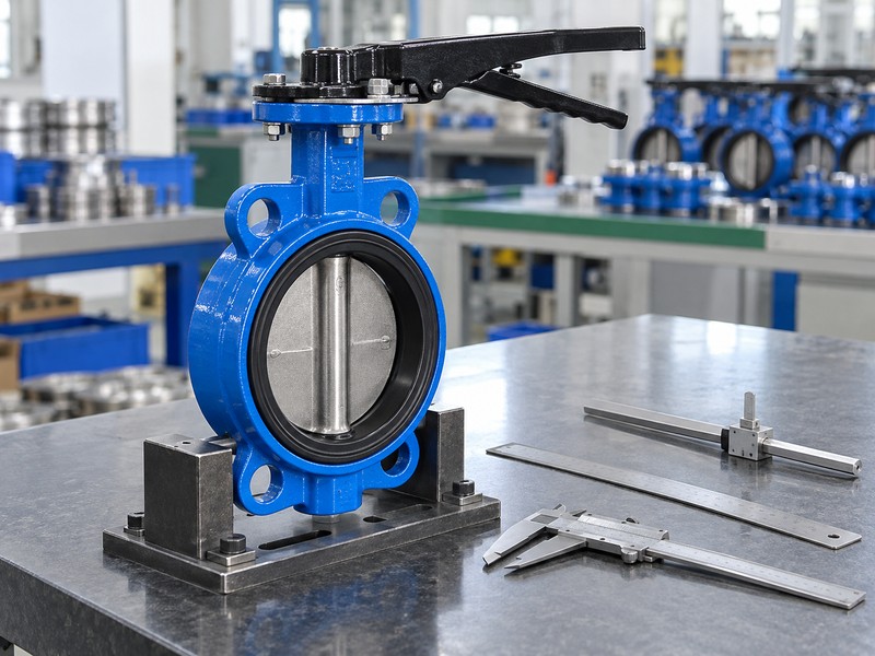
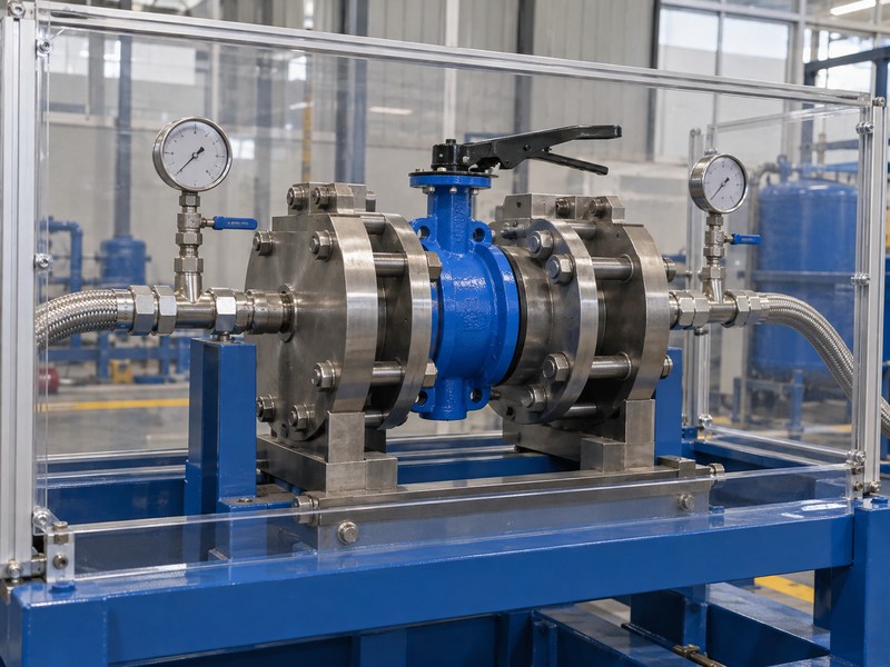
Confirm the opening’s intended function. A port or blank cover can serve a purpose unrelated to supervision, and its presence does not authorize housing modification or an improvised bracket. Review conduit routing, enclosure removal space and nearby pipework within the permitted arrangement. The static rig illustration shows external layout only; it proves no switch fit, coupling engagement, electrical connection or commissioned performance.
- Confirm the designated attachment and mounting orientation.
- Check enclosure, conduit and maintenance access space.
- Keep modifications within an explicitly authorized arrangement.
Key takeaway: Mechanical fit includes target alignment and service space, beyond the attachment thread.
| Check | What you should confirm |
|---|---|
| Attachment | Selected valve version has a documented mounting arrangement |
| Envelope | Housing and conduit clear nearby installed equipment |
| Service | Access permits the required inspection and maintenance |

5. Which position suits tamper switch for butterfly valve service?
Define the normal valve position required for tamper switch for butterfly valve service before selecting an external device. A switch designed to monitor an open valve needs its documented open-position arrangement. A closed-position application requires equipment intended for that duty rather than a reversal of contact labels.
Can contact selection reverse the mechanical duty?
Separate position from electrical continuity. Normally open and normally closed contact names refer to the selected switch diagram, while normal valve position follows the application and mechanism. The reviewed PCVS arrangement monitors the open position; that capability cannot establish closed supervision for an unrelated valve. Identify the permitted changed and restored conditions from the selected assembly documentation without assuming a shared trip angle or handwheel movement.
- State intended normal position for the actual valve location.
- Match that position with documented device capability.
- Read contact states using the selected reference diagram.
Key takeaway: A contact-pair change cannot convert a mechanical supervision arrangement into another valve-position design.
| Check | What you should confirm |
|---|---|
| Normal valve | Application defines its required mechanical position |
| Switch duty | Selected arrangement monitors the documented position |
| Contact state | Diagram defines continuity for that configuration |
6. What input suits a tamper switch for butterfly valve kit?
A tamper switch for butterfly valve kit needs contacts compatible with the selected monitored fire alarm input. Keep its supervisory duty separate from any auxiliary contact or optional cover-tamper function. A switch’s stated contact rating describes permitted electrical duty rather than an assumed supply requirement.
What does the input-module boundary include?
Retain the selected panel and module requirements. In an addressable arrangement, the compatible module connects with the panel’s signaling line circuit, or SLC, while valve dry contacts use its separate monitored input or IDC. Ordinary dry contacts must not connect directly across the SLC. Input topology, end-of-line components, programming and fault interpretation follow the chosen equipment and approved project interface documents.
- Identify the permitted supervisory contact and input duty.
- Separate module communication from its monitored contact circuit.
- Use selected equipment data for circuit components and limits.
Key takeaway: Mechanical compatibility and input compatibility require their own evidence for the replacement arrangement.
| Check | What you should confirm |
|---|---|
| Switch | Contacts suit the assigned supervisory input duty |
| Module | Compatible equipment receives its separate monitored input |
| Panel | Approved configuration assigns event type and location |
7. Which tamper switch for butterfly valve parts match?
Replacement parts for a tamper switch for butterfly valve application must match the manufacturer’s permitted component or kit definition. Identify switch version, mounting hardware, linkage parts and applicable instructions. An electrically similar microswitch can leave mechanical operation, environmental protection and approval coverage unverified.
When is a kit more than a switch?
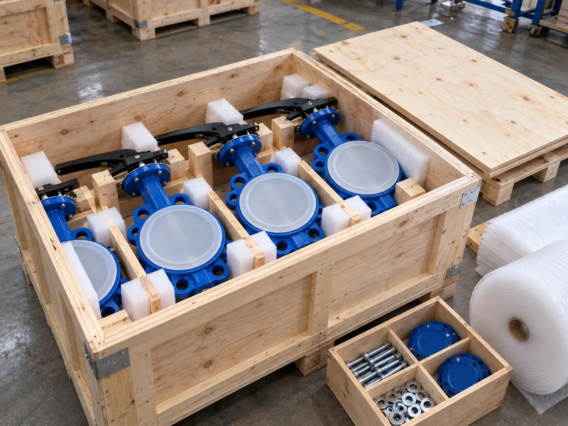
Read the complete parts scope. A kit can include application-specific brackets, fasteners or operating pieces whose geometry controls how the switch follows the valve. The reviewed butterfly-valve documents also restrict certain external accessories to identified versions without factory-installed internal switches. Keep kit identity tied to the valve version rather than combining apparently compatible parts from separate arrangements or substituting workshop hardware without approval.
- Match replacement identity with the permitted parts information.
- Retain specified mounting and operating pieces in the kit.
- Check restrictions linked to existing internal supervision.
Key takeaway: Treat the documented replacement kit as a defined arrangement rather than a collection of equivalent-looking parts.
| Check | What you should confirm |
|---|---|
| Device | Replacement model and version match permitted scope |
| Kit | Specified brackets and operating parts remain identified |
| Valve version | Accessory eligibility matches the actual assembly |
8. When should a tamper switch for butterfly valve retrofit stop?
Stop a tamper switch for butterfly valve retrofit review when the permitted mechanical or approval basis remains unresolved. Examples include an unidentified operator, no documented target arrangement or a proposed modification outside available instructions. A complete factory-supervised assembly may provide a clearer option for project review.
When does an assembly alternative need consideration?
Compare the available documented routes. Retaining the valve may suit an identified replacement arrangement, while an unsupported operator or unavailable permitted kit can justify evaluating a complete assembly. Neither route gains fire approval merely through similar hardware or a supplier assurance. RUITO can review application and assembly information, but actual switch availability and required fire-service approval coverage need confirmation for the proposed supply.
- Identify missing mechanical or approval evidence explicitly.
- Compare documented replacement with a complete assembly alternative.
- Return changed configurations for the required project review.
Key takeaway: Choose a documented route without treating successful physical fit as restored approval.
| Check | What you should confirm |
|---|---|
| Retain valve | A documented permitted replacement route is available |
| Review assembly | A complete identified alternative addresses unresolved compatibility |
| Approval | Actual configuration coverage requires independent confirmation |

9. What verifies a tamper switch for butterfly valve retrofit?
Verification of a tamper switch for butterfly valve retrofit needs the selected mechanical criteria and installed supervisory response. An enclosure mounted securely on its bracket does not prove that the target operates its switch correctly. Define the required acceptance observations through the authorized project procedure.
Which observations belong in the verification record?
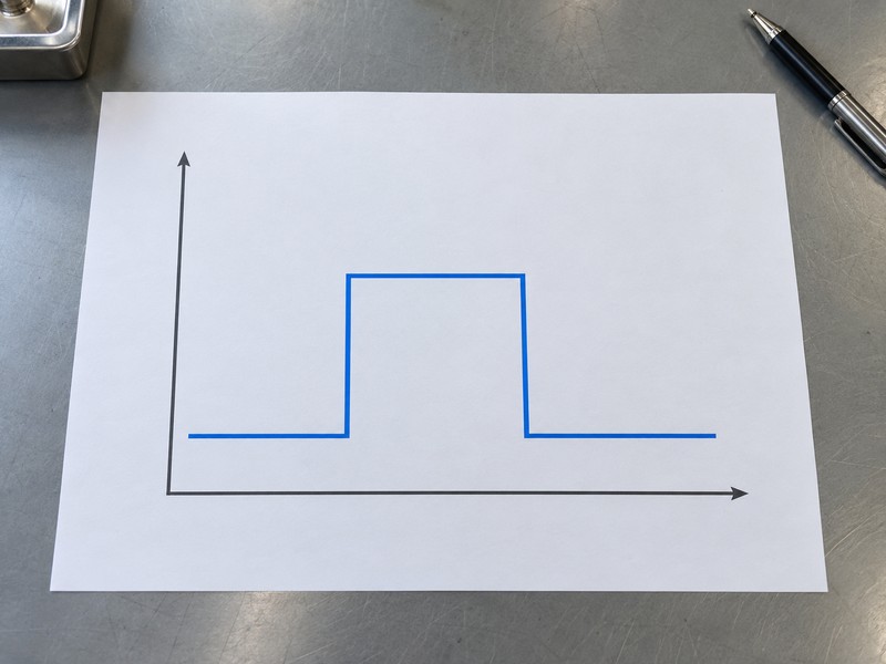
Assign physical work to the authorized team. Its procedure should correlate actual valve position, permitted target movement, designated input indication and restoration using the selected equipment’s criteria and project controls. The abstract chart depicts initial, changed and restored states without polarity, voltage, time, angle or test results. Supervision reports its monitored position relationship; it does not prevent movement or prove waterflow, available supply or seat tightness.
- Record actual assembly identity against the approved arrangement.
- Correlate mechanical observations with the intended supervisory point.
- Apply selected criteria for changed and restored conditions.
Key takeaway: Verify the complete sensing path through authorized observations rather than an assumed universal switching threshold.
| Check | What you should confirm |
|---|---|
| Mechanical | Target and actuator follow the permitted arrangement |
| Supervisory | Identified input reports its assigned condition |
| Restoration | Accepted mechanical and input states return as specified |
10. What records close a tamper switch for butterfly valve retrofit?
Close a tamper switch for butterfly valve retrofit with records showing what changed and which configuration remains installed. Retain valve and operator identity, replacement part numbers, mounting detail, selected instructions and accepted interface information. Future maintenance needs the installed arrangement rather than an outdated generic switch description.
How should later maintenance preserve the accepted arrangement?
Keep the replacement decision traceable. Record approved deviations, completed verification, normal position and any maintenance restrictions, then update the applicable site documents. Later inspections and tests follow the adopted requirements, selected product instructions and project arrangements without a universal schedule. A hydraulic report addresses its stated pressure or leakage scope; the pressure-test illustration supplies no result and cannot replace the retrofit’s mechanical and electrical acceptance evidence.
- Update installed part identity and approved mounting information.
- Retain verification results and accepted technical deviations.
- Keep mechanical, hydraulic and supervisory evidence within stated scope.
Key takeaway: Leave a traceable installed configuration that later service teams can identify and review.
| Check | What you should confirm |
|---|---|
| Installed record | Identity and documents describe the accepted replacement |
| Verification | Required mechanical and supervisory results are retained |
| Maintenance | Selected instructions govern later work and substitutions |
Send RUITO the valve and operator markings, existing switch identity, intended normal position and available mounting documents. We can review the application information and identify unresolved assembly questions before a replacement route is proposed. Contact us with those records for a configuration-specific review.
FAQ
Q1: Can any microswitch replace a valve supervisory switch?
No. Use the permitted device or replacement kit for the identified valve arrangement, including its mechanical and approval restrictions.
Q2: Does a matching mounting thread prove compatibility?
No. Review the operating target, actuator movement, mounting orientation, service space and configuration coverage against selected instructions.
Q3: Can an OS&Y switch be used on a butterfly operator?
Only if the exact application is documented and accepted. A common supervisory purpose does not establish matching targets or mounting arrangements.
Q4: Does a successful retrofit automatically preserve fire approval?
No. Confirm actual approval scope for the valve, operator, switch and permitted accessories, including any proposed modification.
Q5: When should I evaluate a complete supervised assembly?
Review that route when the existing operator cannot be identified or a permitted replacement and mounting arrangement cannot be established.