
A butterfly valve gearbox reduces handwheel speed and transmits torque to the valve shaft through a reduction mechanism. Choose it from the valve duty, permitted operator effort and actual mounting arrangement. Valve size alone leaves several selection questions unanswered.
Your replacement operator may fit the bolt holes yet require awkward handwheel access or exceed the shaft limit during seating. Those problems often appear after a seemingly economical purchase. Compare the complete valve and operator package before releasing the order, with operating demand and component capacity stated at their actual application points.
1. What does a butterfly valve gearbox do?
A butterfly valve gearbox connects multiple handwheel turns with the smaller rotation required at the valve shaft. Its reduction arrangement can lower the input torque needed for a given output demand, subject to actual efficiency and ratings. The valve disc still follows the accepted travel of its own design.
Which operating changes should you expect?
Follow the input and output separately. A direct lever turns with the shaft, whereas a reduction operator trades input movement for mechanical advantage. The gearbox adds height, mass and maintenance access needs to the assembly. Its presence does not change seat material, pressure rating or the valve body connection, so retain the valve specification alongside the operator schedule when comparing offers.
- Separate handwheel movement from valve-shaft rotation.
- Compare the complete operator and valve envelope.
- Keep the valve pressure and material specification intact.
Key takeaway: Select the gearbox as part of an identified valve assembly with defined operating requirements.
| Check | What you should confirm |
|---|---|
| Input | Handwheel turns enter the reduction mechanism |
| Output | Shaft rotation follows accepted valve travel |
| Package | Operator adds its own mass and space requirements |
2. What duty sizes a butterfly valve gearbox?
A butterfly valve gearbox needs the actual medium, operating temperature, differential pressure and frequency of movement before sizing. Pressure across a closed or moving disc affects its operating demand. Nominal pipe pressure and valve diameter cannot describe every point of the operating cycle or every seating condition.
What belongs in the duty schedule?
Describe the real operating cases. Record normal service, the largest permitted closing differential and any reversal that changes the valve loading. State whether operators make occasional isolation movements or frequent adjustments, then request the valve torque basis for that duty. RUITO selects valve materials and drive arrangements against the supplied application; separate fluid configurations retain their own limits and acceptance records.
- State medium composition and operating temperature.
- Identify the closing differential and flow direction.
- Record movement frequency and intended operating cases.
Key takeaway: Give suppliers operating cases that can support a torque selection, including the demanding case.
| Check | What you should confirm |
|---|---|
| Process | Medium and temperature belong to one configuration |
| Differential | Pressure difference applies across the actual valve |
| Duty | Movement frequency and operating cases are stated |
3. What torque matches a butterfly valve gearbox?
A butterfly valve gearbox must cover documented valve demand while respecting its input, output and connected-component limits. Request breakaway, running and seating requirements for the actual service. A catalogue maximum output value describes capacity at a stated duty; it does not tell you how much torque the selected valve needs.
How should competing torque figures be compared?
Locate every torque value. A handwheel input rating belongs on the input shaft, while valve demand belongs at the output connection. Compare like units and application points, then check the stem, coupling and bracket load path. Any sizing allowance should have an identified project basis, separate from a margin already included in the manufacturer rating; avoid adding factors without understanding their purpose.
- Locate demand and ratings at their application points.
- Compare torque units and defined operating conditions.
- Review stem, coupling and bracket limits with the operator.
Key takeaway: Approve the torque chain from the handwheel input through the valve shaft and mounting.
| Check | What you should confirm |
|---|---|
| Demand | Valve torque follows actual differential and duty |
| Capacity | Input and output ratings remain separate |
| Margin | Selection allowance has a stated project basis |
4. What effort suits a butterfly valve gearbox?
A butterfly valve gearbox should meet the permitted handwheel effort at the actual installed position. Hand force depends on the required input torque and effective wheel radius, with access affecting whether the operator can apply that force comfortably. A larger wheel also needs more clearance around pipework, supports and adjacent equipment.
What should the handwheel review include?
Check the working position. Record wheel diameter, grip access, operator reach and the available standing area before accepting an effort figure. An illustrative calculation can divide tangential input torque by effective wheel radius, provided both quantities use consistent units. Actual acceptance still needs the selected operator data and project ergonomic requirements; a nominal gear ratio does not establish a permitted hand force.
- Review wheel diameter and effective grip radius.
- Check reach, standing area and hand clearance.
- Use the selected input rating and effort acceptance basis.
Key takeaway: Compare handwheel effort and access together before choosing a wheel or reduction arrangement.
| Check | What you should confirm |
|---|---|
| Effort | Tangential force relates to input torque and radius |
| Access | Installed position permits the intended manual action |
| Envelope | Wheel sweep clears nearby physical obstructions |
5. What turns suit a butterfly valve gearbox?
A butterfly valve gearbox needs an accepted number of input turns for the required output travel. More reduction can reduce input torque but increases handwheel movement for the same shaft rotation. Include every reduction stage and ask how the supplier defines its published ratio and endpoint turn count.
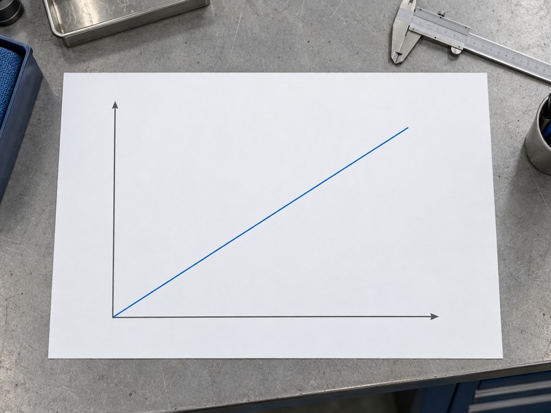
How can the input-output chart help?
Read the chart as a motion relationship. For an ideal input-to-output angular ratio i, handwheel turns equal i multiplied by output angle in degrees divided by 360. The straight line illustrates that fixed relationship without measured performance data. It cannot establish backlash, efficiency, seating load or operator response, which require separate selected-product information and the accepted assembly settings.
- Identify the complete input-to-output ratio definition.
- Use the required output travel for the selected valve.
- Confirm actual turns from the complete operator schedule.
Key takeaway: Balance manual effort against the time and movement needed for the accepted stroke.
| Check | What you should confirm |
|---|---|
| Ratio | Definition identifies all installed reduction stages |
| Motion | Input turns and output angle remain distinct |
| Acceptance | Selected endpoint data govern actual permitted travel |
6. What fit matches a butterfly valve gearbox?
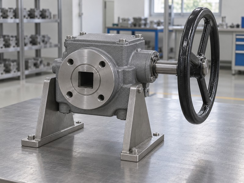
A butterfly valve gearbox fits only when its mounting face and drive connection match the actual valve assembly. Bolt holes, locating features, thread depth, shaft profile and usable engagement all need review. A nominal flange label can help identify an attachment family while leaving several mating dimensions unresolved.
Which interfaces need their own evidence?
Inspect the whole connection. ISO 5211 addresses part-turn actuator attachments, but the selected assembly still needs its actual mating details. Compare square orientation or bore-and-key geometry, axial clearance, retention and the support arrangement. A socket can appear suitable yet bottom before the mounting faces seat, so request a dimensioned drive detail when the general arrangement does not resolve engagement.
- Check mounting holes, locating features and threads.
- Match the actual shaft profile and its orientation.
- Verify usable engagement, clearance and retention.
Key takeaway: Close mounting and drive fit as separate checks before treating an operator as interchangeable.
| Check | What you should confirm |
|---|---|
| Mount | Actual hole pattern and seating features agree |
| Drive | Mating profile and tolerances are identified |
| Engagement | Connection transmits load without axial bottoming |
7. What holding suits a butterfly valve gearbox?
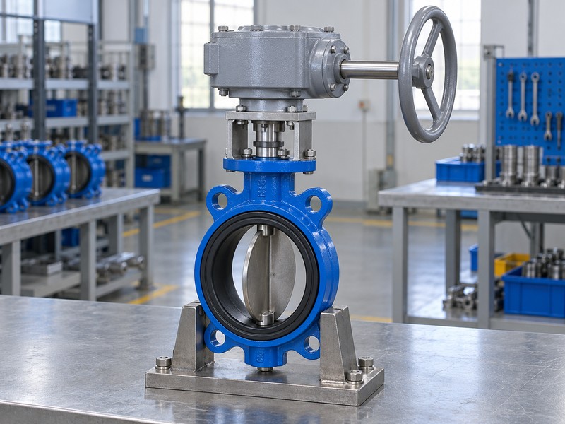
A butterfly valve gearbox needs documented holding behaviour for the intended loads and operating conditions. A worm mechanism may resist back-driving under specified conditions, but the word worm cannot establish a universal self-locking guarantee. The selected product information must state any applicable holding limits, restrictions and required supplementary arrangement.
What does a position indicator establish?
Read the pointer within its scope. It shows the mechanism position according to its indexing and setting; it does not directly prove sealing or confirm that a loose coupling still drives the disc correctly. Compare accepted endpoints and any project locking requirement separately. If service requires a defined retained position, make that requirement explicit instead of relying on an operator photograph or an unqualified catalogue phrase.
- Request the selected holding or back-drive limitations.
- Define any required locking or retained-position function.
- Separate pointer indication from sealing acceptance.
Key takeaway: Specify the required holding and indication functions with evidence for the selected operator.
| Check | What you should confirm |
|---|---|
| Holding | Documented limits match the applied conditions |
| Indication | Pointer indexing corresponds to accepted travel |
| Locking | Project retention requirements are explicitly addressed |
8. What exposure suits a butterfly valve gearbox?
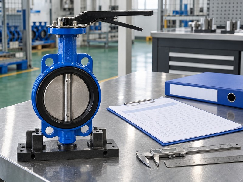
A butterfly valve gearbox must suit its external environment and mechanical load. Outdoor water, washdown, coastal exposure, dust and temperature can require different sealing and coating choices. An ingress-protection designation applies under defined test conditions and cannot by itself establish indefinite immersion life or complete corrosion resistance.
What environmental details should procurement retain?
Describe the exposure directly. State installation location, expected water contact, ambient temperature and access for inspection, then request the supplier environmental limits for the assembled operator. Keep coating, seals, fasteners and any extension arrangement in the same approved configuration. Process-fluid compatibility belongs to the valve wetted parts; external salt spray and a seawater flow path are different material-selection questions.
- Describe actual external water, dust and corrosion exposure.
- Request coating, sealing and ambient-temperature limits.
- Keep external exposure separate from the valve medium.
Key takeaway: Specify environmental service in words and conditions before comparing protection labels.
| Check | What you should confirm |
|---|---|
| Location | Installation exposure is described without shorthand |
| Protection | Selected enclosure and coating limits are documented |
| Materials | External and wetted-part requirements are distinguished |
9. What options replace a butterfly valve gearbox?
A butterfly valve gearbox should be compared with a lever or powered operator against the same valve duty. A lever can suit accessible, acceptable-effort isolation, while manual reduction can suit loads that require lower input effort. Remote commands, defined failure action or automatic movement require their own powered arrangement and control requirements.
How should your team compare operating methods?
Start with the task. Decide who operates the valve, how often movement occurs and whether an operator must be physically present at the wheel. Compare complete installed cost, service access, feedback and operating time after the torque and interface questions close. Adding a gearbox does not create remote control, and adding a powered actuator does not remove the need to check the valve shaft and mounting loads.
- Compare all operating methods against identical valve duty.
- State local operation, remote control and feedback needs.
- Include installed access and maintenance in the comparison.
Key takeaway: Choose an operating method from the actual job, then review its complete assembled configuration.
| Check | What you should confirm |
|---|---|
| Lever | Direct operation meets effort and access requirements |
| Gearbox | Manual reduction suits the accepted input effort |
| Powered | Control, supply and failure-action needs are defined |
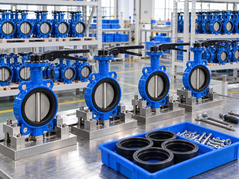
10. What orders a butterfly valve gearbox correctly?
A butterfly valve gearbox enquiry should identify the valve, required duty, torque basis, operating effort, drive interface and installation envelope. Ask the supplier to list the selected operator, supplied mounting parts and applicable documents together. This gives purchasing a clear package to compare and engineering a defined configuration to review.
Which records should remain with the order?
Keep the order traceable. Retain the accepted general arrangement, drive detail, component definition, torque selection and selected installation and maintenance information. Record unresolved exceptions before approval and define how substitutions receive review. RUITO can evaluate the proposed valve assembly against supplied application information; the selected operator documents should accompany its actual configuration rather than remain a generic attachment to the quotation.
- Link the quote to an identified valve and operator.
- Close technical exceptions before order release.
- Retain accepted documents and change-review decisions.
Key takeaway: Purchase one defined valve-operator package with supporting records that match its accepted revision.
| Check | What you should confirm |
|---|---|
| Enquiry | Application and interface data describe one package |
| Offer | Selected parts and exceptions are clearly identified |
| Release | Accepted records match the purchased configuration |
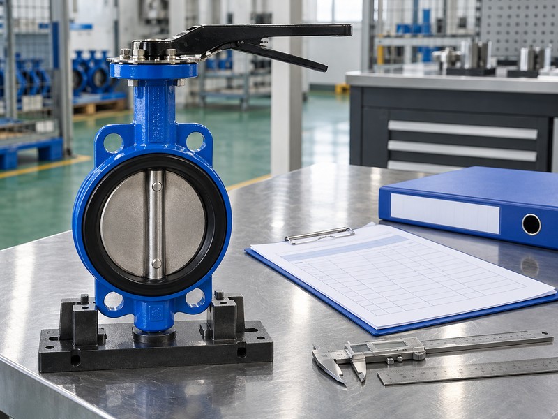
Send RUITO the valve identification, operating conditions and available mounting drawings. We can review the proposed assembly and identify the torque, drive and access information still needed. Contact us with those details before purchasing a replacement operator.
FAQ
Q1: Can I choose a gearbox from valve diameter alone?
No. Provide differential pressure, medium, temperature, valve torque, size and the intended operating duty.
Q2: What’s the best ratio for a butterfly valve?
Use the selected duty. Balance permitted handwheel effort with actual input turns, operating time and operator ratings.
Q3: Can a matching flange prove interchangeability?
No. Check drive geometry, tolerances, engagement, axial clearance, mounting threads and the complete support arrangement.
Q4: How do I know whether the gearbox holds position?
Request the selected product limits. Holding and back-drive behaviour depend on the mechanism and operating conditions.
Q5: Can a gearbox add remote control?
A manual gearbox alone cannot. Remote movement needs an approved powered arrangement, supply and control specification.